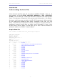
1
SHUTTLE BOX STEP DOWN
MED-STATE NOTATION
SOF-700RA-11L User’s Manual
DOC-218
Rev. 1.0
Copyright © 2008
All Rights Reserved
MED Associates Inc.
P.O. Box 319
St. Albans, Vermont 05478
www.med-associates.com
Trademarks: MedState Notation™, MED Associates, Inc.
Registered Trademark:
MED-PC ® ; MED Associates, Inc.
Delphi ® ; Borland International, Inc.
TM
PROCEDURE
MED ASSOCIATES INC.
SHUTTLE BOX STEP DOWN
- i -
MED ASSOCIATES INC.
SHUTTLE BOX STEP DOWN
TABLE OF CONTENTS
Chapter 1 .............................................................................................. 1
Introduction ...................................................................................................... 1
Overview of the Procedures .............................................................................. 2
Chapter 2 .............................................................................................. 3
Getting Started .................................................................................................. 3
Software Installation ....................................................................................... 3
Backing Up the Software .................................................................................. 3
Chapter 3 .............................................................................................. 4
Beginning & Running an Experiment ..................................................................... 4
Translating The MED-PC IV (.mpc) File............................................................... 4
Using the MED-PC IV Load Wizard ..................................................................... 5
Viewing/Changing Variable Values ................................................................... 10
Chapter 4 ............................................................................................ 12
Modifying the MED State Notation TM Procedures ................................................... 12
Shuttle Box Step Down Training Level.mpc ....................................................... 12
Shuttle Box Step Down Test Level.mpc............................................................. 16
Chapter 5 ............................................................................................ 21
Understanding the Data Files ............................................................................. 21
Sample Data File ........................................................................................... 21
- ii -
MED ASSOCIATES INC.
SHUTTLE BOX STEP DOWN
- iii -
MED ASSOCIATES INC.
SHUTTLE BOX STEP DOWN
CHAPTER 1
Introduction
IMPORTANT NOTE: All inputs must be set to Level Mode when running the Shuttle Box
Step Down Training Level.mpc and Shuttle Box Step Down Test Level.mpc applications.
The purpose of this manual is to give an explanation of the MED State Notation™
Procedures that comprise the SOF-700RA-11L Shuttle Box Step Down Procedures. The
files in this package can be found on the disk provided by MED Associates, Inc.
These procedures are intended to be run in MED Associates MED-PC ® IV software. The
latest version of MED-PC ® IV gives researchers the ability to use pre-programmed
procedures such as these to make hardware control and data collection easy. These preprogrammed procedures can also be modified to meet the evolving demands of a
research protocol. Again, it is the intent of this manual to explain exactly what these
procedures implement, and provide guidance into how to interpret what the program
code achieves in order to allow the user determine how to modify them to match their
research protocol demands.
The manual provides some examples of editing and
modifying the procedure’s programming code. The manual also defines the elements in
the raw data file produced by these procedures.
In addition to this manual, refer to the MED-PC ® IV User’s Manual for the installation
of the MED-Associates interface drivers, the MED-PC IV Software, and the Delphi ®
Compiler. Also refer to the User’s Manual for instructions on developing a Hardware
Configuration. Data file structure, file-saving format, and other related options are also
determined by the Hardware Configuration.
The Hardware Configuration software
utility’s purpose is to assign the inputs and outputs on the interface cards in the interface
cabinet for each task controlled by MED-PC IV. The particular type of interface card that
is supplied in the interface cabinet may vary; please refer to the User’s Manual provided
for instructions on how to configure the type of card that is in the cabinet. A valid
Hardware Configuration must exist in order for MED-PC IV to interface correctly with the
MED Associates, Inc. hardware. This means that one should take the time to create a
valid Hardware Configuration before attempting to run the procedures included in this
package.
Should there be any problems, the staff at MED Associates, Inc. is available to answer
any questions that may arise. Please e-mail us at [email protected] with a
detailed description of the problem or desired goals so that concise and detailed
information may be provided.
The Shuttle Box Step Down procedures are designed to be as easy to use as possible.
MED Associates, Inc. understands that researchers do not have the time to devote to
programming and hardware design, and for that reason, we have undertaken that burden
for you. We sincerely hope that you are satisfied with the products and services we
provide, and look forward to meeting your future experimental needs as your research
program evolves.
- 1 -
MED ASSOCIATES INC.
SHUTTLE BOX STEP DOWN
Overview of the Procedures
IMPORTANT NOTE: All inputs must be set to Level Mode when running the Shuttle Box
Step Down Training Level.mpc and Shuttle Box Step Down Test Level.mpc applications.
The Shuttle Box Step Down Protocols procedures are written for systems with eight I/R
photobeam sensors. The platform should be placed so the subject steps into the right
side when stepping down off the platform.
In the training procedure, delay to aversive stimulation onset is 0.001" seconds, aversive
stimulation duration is 2 seconds, no response time is 180 seconds, and the inter-trial
interval is 120 seconds. In the test procedure, no response time is 180 seconds, and the
inter-trial interval is 120 seconds. No aversive stimulation is used in the test procedure.
The data collected in both procedures are the trial numbers and the response latencies.
The training and testing procedures are included in both Level and Toggle mode. The
Level mode procedures will run only in Level Mode.
- 2 -
MED ASSOCIATES INC.
SHUTTLE BOX STEP DOWN
CHAPTER 2
Getting Started
Software Installation
Please refer to the “MED-PC IV User’s Manual” for a complete guide to installing the
MED-PC IV software. After MED-PC IV is installed on the computer, five separate icons
should appear on the desktop screen: (1) MED Test, (2) Hardware Configuration, (3)
Trans IV, (4) MED-PC IV, and (5) MED-PC To Excel.
The Shuttle Box Step Down package includes a CD containing several MED-PC testing
protocols, these include:
Shuttle
Shuttle
Shuttle
Shuttle
Box
Box
Box
Box
Step
Step
Step
Step
Down
Down
Down
Down
Training Level.mpc
Test Level.mpc
Training.mpc
Test.mpc
To install the Shuttle Box Step Down Training Level and Shuttle Box Step Down Test
Level protocols, insert the CD into the CD-ROM drive and click Install the Shuttle Box
Step Down Software. If the Shuttle Box Step Down Training or Shuttle Box Step Down
Test protocols are to be used, they must be copied manually into the C:\MED-PC
IV\MPC folder.
Backing Up the Software
Med Associates strongly encourages creating backup copies of the Shuttle Box Avoidance
programs in case of disk failure. Having copies of the original programs may be useful in
the future should modifications be made to the existing programs.
- 3 -
MED ASSOCIATES INC.
SHUTTLE BOX STEP DOWN
CHAPTER 3
Beginning & Running an Experiment
Translating The MED-PC IV (.mpc) File
Programs written in MedState Notation must be translated using Trans IV before they can
be executed in this application. The “MED-PC IV Programmer’s Manual” explains how to
accomplish this translation. Make sure that a copy of the file being translated, is present
in the directory “C:\MED-PC IV\MPC\.” Double click the Trans IV icon on the Start |
Programs list or desktop and select Translation | Translate and Compile.
Select the program to use for the experiment and select Make. Click OK to start the
translator, and it should automatically parse the MedState Notation and then open to a
DOS screen to compile the Pascal code. Depending on the speed of the computer, each
of these steps may not be seen. If any problems are encountered during this process,
refer to the on-screen help menu, the “MED-PC Version IV User’s Manual”, or contact
MED Associates, Inc., for assistance.
Figure 3.1 - Trans IV Control Panel for Translating and Compiling MedState Notation Code
- 4 -
MED ASSOCIATES INC.
SHUTTLE BOX STEP DOWN
Using the MED-PC IV Load Wizard
IMPORTANT NOTE: All inputs must be set to Level Mode when running the Shuttle Box
Step Down Training Level.mpc and Shuttle Box Step Down Test Level.mpc applications.
MED-PC IV is designed to help the researcher run an experiment by guiding selection
choices through its Experiment Loading Wizard. This section will describe how to initiate
an experiment based upon the Shuttle Box Step Down Training Level.mpc procedure.
The following steps that start this procedure will also apply to all other .mpc procedures.
Open MED-PC IV and the MED-PC Experiment Loading Wizard’s Welcome screen, shown
in Figure 3.2 will appear.
Figure 3.2 - The MED-PC IV Loading Wizard Welcome Screen
To avoid this load wizard, deselect the checkbox labeled “Run this experiment
automatically when starting MED-PC.” Close this screen by clicking the Close button.
Closing this screen immediately reveals the MED-PC Run-Time Screen shown in Figure
3.10.
- 5 -
MED ASSOCIATES INC.
SHUTTLE BOX STEP DOWN
If the choice to continue with the Loading Wizard is made, then select the Next button.
The next screen seen is the Box Selection screen, as shown in Figure 3.3. It is in this
screen that the researcher chooses which boxes will be used in the experiment. Select
the boxes that will run the experiment by clicking in the radio button next to the box
number. The figure shows that the Hardware Configuration included only 1 box, which
was selected.
Figure 3.3 - The Box Selection Screen
The next screen seen is the Select a Procedure screen, as seen in Figure 3.4. This is
where the procedure to be run is selected. The screen displays a list of all the currently
compiled procedures. Simply select the procedure to be run, then click Next.
Figure 3.4 - Select a Procedure Screen
- 6 -
MED ASSOCIATES INC.
SHUTTLE BOX STEP DOWN
The Enter Experiment Data Screen should display next, as shown in Figure 3.5. The
purpose of this screen is to allow annotations to be added to the data file that is
produced by MED-PC IV. These annotations will help identify the Subject, Experiment,
and Experiment Group upon which data was collected. Comments can be added here as
well, and the data file can be given a customized file name to help identify it from other
data files. Enter the information desired, and click Next.
Figure 3.5 - Enter Experiment Data Screen
The next screen to appear is the Review Choices screen, as seen in Figure 3.6. This is a
method of confirming that the information received from the Box/Procedure Selected is
correct. If it is not correct, select Previous, and edit the data. If it is correct, select
Next.
Figure 3.6 - Review Choices Screen
- 7 -
MED ASSOCIATES INC.
SHUTTLE BOX STEP DOWN
The Alter Session Parameters Screen, shown in Figure 3.7, is the next screen to appear,
and is an important screen for the researcher.
The Alter Session Parameters screen
allows the researcher to alter the parameters by which a procedure executes. The Send
Start Command Screen appears next.
The options available on the screen vary
depending upon how many boxes are described in the Hardware Configuration.
Figure 3.7 - Alter Session Parameters Screen
In this example only 1 box is described in the Hardware Configuration, so Figure 3.8 will
appear next. If more than 1 box is in the Hardware Configuration, then Figure 3.9 will
appear.
Figure 3.8 - Send Start Command Screen for Single Box Configuration
- 8 -
MED ASSOCIATES INC.
SHUTTLE BOX STEP DOWN
Figure 3.9 - Send Start Command Screen for Multiple Box Configuration
In both cases (Figure 3.8 and Figure 3.9), the screens are where the researcher decides
to either load more boxes, send a start signal to boxes that are already loaded, or enter
the MED-PC IV run-time environment without sending a start signal by selecting “I am
finished with the wizard”. This option results in the screen shown in Figure 3.10.
Figure 3.10 - The MED-PC IV Run-Time Screen
- 9 -
MED ASSOCIATES INC.
SHUTTLE BOX STEP DOWN
Viewing/Changing Variable Values
Before a “start command” has been issued, any variable may be changed on the MED-PC
IV run-time screen. Simply highlight the value to change, and then enter the new value.
Once a session is in progress, change variables by selecting Configure | Change
Variables, or click the 4th tool bar item ΔX. In the lower left hand corner of the Change
Variables window, find the “Display Data from Box” display, and choose the chamber(s)
to modify. By clicking additional boxes in the “Additional Boxes to Update” section,
changes made to a single box are automatically loaded to all of the selected boxes.
Figure 3.11 - Changing Variables Screen
The value of any simple variable may be viewed from this screen by clicking an array on
the table and each element in that array can be viewed, as shown in Figure 3.12. To
change a value, simply highlight and replace the value in the lower right hand box or use
the up/down arrows to increment by 1. Click the Issue button for the change to take
effect. Click Named Variables to produce the display in Figure 3.13. Change variables
here as needed.
- 10 -
MED ASSOCIATES INC.
SHUTTLE BOX STEP DOWN
Figure 3.12 - Displaying Array A from Box 1
Figure 3.13 - Displaying Named Variables from Box 1
- 11 -
MED ASSOCIATES INC.
SHUTTLE BOX STEP DOWN
CHAPTER 4
Modifying the MED State Notation T M Procedures
The Med State Notation code for both of the Shuttle Box Step Down Level programs are
listed below for reference purposes. Lines beginning with a backslash “\” indicate
comments that help identify key elements of the code and explain the function of each
program step.
Shuttle Box Step Down Training Level.mpc
\ Copyright (C) 2008 MED Associates, All rights reserved.
\
\
\
\
\
\
MED-PC IV Shuttle Box Step Down Training Level Procedure for systems
with 8 I/R Photobeam sensors. The platform should be placed so the
subject steps into the right side when stepping down off the
platform.
Program runs only in Level Mode.
\ The #1 Beam is the Beam closest to the Door or Hurdle on each side.
\ Inputs are assigned from left to right as viewed from front of Box.
\ Inputs
^LeftIR_4
^LeftIR_3
^LeftIR_2
^LeftIR_1
^RightIR_1
^RightIR_2
^RightIR_3
^RightIR_4
=
=
=
=
=
=
=
=
\ Outputs
^LeftLight
^RightLight
^LeftTone
^RightTone
^Door
^ShockOperate
^LeftGrid
^RightGrid
\ Control
Var_Alias
Var_Alias
Var_Alias
Var_Alias
1
2
3
4
5
6
7
8
=
=
=
=
=
=
=
=
1
2
3
4
5
6
7
8
Variables with Assigned Aliases
Delay to Shock Onset (sec) = D
Shock Duration (sec)
= S
No Response Time
(sec) = R
Inter-Trial Interval (sec) = I
as Defined
\ Default =
\ Default =
\ Default =
\ Default =
0.001 seconds
2 seconds
120 seconds
180 seconds
\ List Data Variables Here
\ P() = Trial by Trial Data
\ P(Q)
= Trial Number
\ P(Q+1) = Response Latency
\ List Working Variables Here
\ A() = System Control Variables.
\ A(0) = Delay to Shock Onset in System Clock Ticks (D * 1")
\ A(1) = Shock Duration in System Clock Ticks (S * 1")
\ A(2) = No Response Time in Seconds
\ A(3) = Inter-Trial Interval in System Clock Ticks (I * 1")
^Delay
= 0
^ShockDur
= 1
^NoResponse = 2
^ITI
= 3
- 12 -
MED ASSOCIATES INC.
\
\
\
\
\
\
\
\
C
D
I
L
Q
R
S
T
=
=
=
=
=
=
=
=
SHUTTLE BOX STEP DOWN
Count of Activity on Left Side
Delay to Shock Onset
Inter-Trial Interval
Response Latency Count in 0.1" Increments
Subscript for Data Array P
No Response Time
Shock Duration
Trial Number
\ Z-Pulses Used in This Procedure
\ Z1 = Start Response Latency Counter "L".
\ Z2 = Signal Entry into "Right" Side, or End of Trial if No Response
\
made within the No Response Time.
\ Z21 = Beam 1 Break
\ Z22 = Beam 2 Break
\ Z23 = Beam 3 Break
\ Z24 = Beam 4 Break
\ Z25 = Beam 5 Break
\ Z26 = Beam 6 Break
\ Z27 = Beam 7 Break
\ Z28 = Beam 8 Break
^StartLatency = 1
^EndTrial
= 2
^One
= 21
^Two
= 22
^Three
= 23
^Four
= 24
^Five
= 25
^Six
= 26
^Seven
= 27
^Eight
= 28
DIM A = 3
DIM P = 100
\ Control Variables Array
\ Data Array
DISKCOLUMNS = 4
\*********************************************
\
MAIN PROGRAM
\*********************************************
S.S.1,
S1,
0.001": SET D = 0.001, I = 120, R = 180, S = 2, T = 1, P(0) = -987.987 ---> S2
S2,
\ Show Shock Delay & Duration Default Times
\ Initiate Trial when Animal is Placed on "Left" Side
#Z^Four ! #Z^Three ! #Z^Two ! #Z^One: CLEAR 1,60;
SET A(^Delay)
= D * 1";
SET A(^ShockDur)
= S * 1";
SET A(^NoResponse) = R;
SET A(^ITI)
= I * 1";
SHOW 1,Trial #,T, 2,Active,C;
Z^StartLatency ---> S4
1": SHOW 1,Trial #,T, 2,Onset Delay,D, 3,Shock Duration,S, 4,No
5,ITI,I ---> SX
S3,
#Z^Four ! #Z^Three ! #Z^Two ! #Z^One: Z^StartLatency ---> S4
S4,
\ Start Trial Sequence
#Z^Seven ! #Z^Eight: Z^EndTrial ---> S5
#Z^EndTrial: ---> S7
S5,
\ Delay to Onset of Shock
A(^Delay)#T: ON ^RightGrid, ^ShockOperate ---> S6
- 13 -
Response
Time,R,
MED ASSOCIATES INC.
SHUTTLE BOX STEP DOWN
S6,
\ Shock Duration
A(^ShockDur)#T: OFF ^RightGrid, ^ShockOperate ---> S7
S7,
\ Inter-Trial Interval (New Trial doesn't actually start until an Animal is
\ placed in the Left Side. This is here to give you a chance to remove an
\ animal. You'll know you can run a new Animal when the Trial Count
\ updates and the Activity Count resets.
A(^ITI)#T: ADD T; SET C = 0, L = 0;
SHOW 1,Trial #,T, 2,Active,C, 3,Latancy,L ---> S3
\*********************************************
\
LEFT MOVEMENT ACTIVITY
\*********************************************
S.S.2,
S1,
#Z^StartLatency: ---> S2
S2,
\ Wait for
#Z^Four: ADD C;
#Z^Three: ADD C;
#Z^Two:
ADD C;
#Z^One:
ADD C;
first Beam Break
SHOW 2,Activity,C
SHOW 2,Activity,C
SHOW 2,Activity,C
SHOW 2,Activity,C
--->
--->
--->
--->
S4
S5
S6
S7
S4,
\ Movement following a Beam 1 Break
#Z^Three: ADD C; SHOW 2,Activity,C ---> S5
#Z^Two:
ADD C; SHOW 2,Activity,C ---> S6
#Z^One:
ADD C; SHOW 2,Activity,C ---> S7
#Z^EndTrial: ---> S1
S5,
\ Movement following a Beam
#Z^Four: ADD C; SHOW 2,Activity,C
#Z^Two: ADD C; SHOW 2,Activity,C
#Z^One: ADD C; SHOW 2,Activity,C
#Z^EndTrial: ---> S1
2 Break
---> S4
---> S6
---> S7
S6,
\ Movement following a Beam 3 Break
#Z^Four: ADD C; SHOW 2,Activity,C ---> S4
#Z^Three: ADD C; SHOW 2,Activity,C ---> S5
#Z^One:
ADD C; SHOW 2,Activity,C ---> S7
#Z^EndTrial: ---> S1
S7,
\ Movement following a Beam 4 Break
#Z^Four: ADD C; SHOW 2,Activity,C ---> S4
#Z^Three: ADD C; SHOW 2,Activity,C ---> S5
#Z^Two:
ADD C; SHOW 2,Activity,C ---> S6
#Z^EndTrial: ---> S1
\*********************************************
\
RESPONSE LATENCY DETERMINATION
\*********************************************
S.S.3,
S1,
#Z^StartLatency: ---> S2
S2,
#Z^EndTrial: SET P(Q) = T, P(Q+1) = L;
SET Q = Q + 2, P(Q) = -987.987 ---> S1
0.1": SET L = L + 0.1; SHOW 3,Latancy,L;
IF L >= A(^NoResponse) [@EndTrial, @ContinueTiming]
@End: SET P(Q) = T, P(Q+1) = L;
SET Q = Q + 2, P(Q) = -987.987;
Z^EndTrial ---> S1
@Cont: ---> SX
\*********************************************
\
BEAM 1 BREAK
\*********************************************
S.S.21,
S1,
#START: ---> S2
S2,
#R^LeftIR_4: Z^One ---> S3
S3,
#R^LeftIR_4: ---> SX
0.01": ---> S2
- 14 -
MED ASSOCIATES INC.
SHUTTLE BOX STEP DOWN
\*********************************************
\
BEAM 2 BREAK
\*********************************************
S.S.22,
S1,
#START: ---> S2
S2,
#R^LeftIR_3: Z^Two ---> S3
S3,
#R^LeftIR_3: ---> SX
0.01": ---> S2
\*********************************************
\
BEAM 3 BREAK
\*********************************************
S.S.23,
S1,
#START: ---> S2
S2,
#R^LeftIR_2: Z^Three ---> S3
S3,
#R^LeftIR_2: ---> SX
0.01": ---> S2
\*********************************************
\
BEAM 4 BREAK
\*********************************************
S.S.24,
S1,
#START: ---> S2
S2,
#R^LeftIR_1: Z^Four ---> S3
S3,
#R^LeftIR_1: ---> SX
0.01": ---> S2
\*********************************************
\
BEAM 5 BREAK
\*********************************************
S.S.25,
S1,
#START: ---> S2
S2,
#R^RightIR_1: Z^Five ---> S3
S3,
#R^RightIR_1: ---> SX
0.01": ---> S2
\*********************************************
\
BEAM 6 BREAK
\*********************************************
S.S.26,
S1,
#START: ---> S2
S2,
#R^RightIR_2: Z^Six ---> S3
S3,
#R^RightIR_2: ---> SX
0.01": ---> S2
- 15 -
MED ASSOCIATES INC.
SHUTTLE BOX STEP DOWN
\*********************************************
\
BEAM 7 BREAK
\*********************************************
S.S.27,
S1,
#START: ---> S2
S2,
#R^RightIR_3: Z^Seven ---> S3
S3,
#R^RightIR_3: ---> SX
0.01": ---> S2
\*********************************************
\
BEAM 8 BREAK
\*********************************************
S.S.28,
S1,
#START: ---> S2
S2,
#R^RightIR_4: Z^Eight ---> S3
S3,
#R^RightIR_4: ---> SX
0.01": ---> S2
Shuttle Box Step Down Test Level.mpc
\ Copyright (C) 2008 MED Associates, All rights reserved.
\
\
\
\
\
\
MED-PC IV Shuttle Box Step Down Test Level Procedure for systems
with 8 I/R Photobeam sensors. The platform should be placed so the
subject steps into the right side when stepping down off the
platform. No shock is used in this procedure.
Program runs only in Level Mode.
\ The #1 Beam is the Beam closest to the Door or Hurdle on each side.
\ Inputs are assigned from left to right as viewed from front of Box.
\ Inputs
^LeftIR_4 = 1
^LeftIR_3 = 2
^LeftIR_2 = 3
^LeftIR_1 = 4
^RightIR_1 = 5
^RightIR_2 = 6
^RightIR_3 = 7
^RightIR_4 = 8
\ Outputs
^LeftLight
=
^RightLight
=
^LeftTone
=
^RightTone
=
^Door
=
^ShockOperate =
^LeftGrid
=
^RightGrid
=
1
2
3
4
5
6
7
8
\ Control Variables with Assigned Aliases as Defined
Var_Alias No Response Time
(sec) = R \ Default = 120 seconds
Var_Alias Inter-Trial Interval (sec) = I \ Default = 180 seconds
\ List Data Variables Here
\ P() = Trial by Trial Data
\ P(Q)
= Trial Number
\ P(Q+1) = Response Latency
- 16 -
MED ASSOCIATES INC.
SHUTTLE BOX STEP DOWN
\ List Working Variables Here
\ A() = System Control Variables.
\ A(0) = Delay to Shock Onset in System Clock Ticks (D * 1")
\ A(1) = Shock Duration in System Clock Ticks (S * 1")
\ A(2) = No Response Time in Seconds
\ A(3) = Inter-Trial Interval in System Clock Ticks (I * 1")
^Delay
= 0
^ShockDur
= 1
^NoResponse = 2
^ITI
= 3
\
\
\
\
\
\
C
I
L
Q
R
T
=
=
=
=
=
=
*** Not Used ***
*** Not Used ***
Count of Activity on Left Side
Inter-Trial Interval
Response Latency Count in 0.1" Increments
Subscript for Data Array P
No Response Time
Trial Number
\ Z-Pulses Used in This Procedure
\ Z1 = Start Response Latency Counter "L".
\ Z2 = Signal Entry into "Right" Side, or End of Trial if No Response
\
made within the No Response Time.
\ Z21 = Beam 1 Break
\ Z22 = Beam 2 Break
\ Z23 = Beam 3 Break
\ Z24 = Beam 4 Break
\ Z25 = Beam 5 Break
\ Z26 = Beam 6 Break
\ Z27 = Beam 7 Break
\ Z28 = Beam 8 Break
^StartLatency = 1
^EndTrial
= 2
^One
= 21
^Two
= 22
^Three
= 23
^Four
= 24
^Five
= 25
^Six
= 26
^Seven
= 27
^Eight
= 28
DIM A = 3
DIM P = 100
\ Control Variables Array
\ Data Array
DISKCOLUMNS = 4
\*********************************************
\
MAIN PROGRAM
\*********************************************
S.S.1,
S1,
0.001": SET I = 120, R = 180, T = 1, P(0) = -987.987 ---> S2
S2,
\ Show Shock Delay & Duration Default Times
\ Initiate Trial when Animal is Placed on "Left" Side
#Z^Four ! #Z^Three ! #Z^Two ! #Z^One: CLEAR 1,60;
SET A(^NoResponse) = R;
SET A(^ITI)
= I * 1";
SHOW 1,Trial #,T, 2,Active,C;
Z^StartLatency ---> S4
1": SHOW 1,Trial #,T, 4,No Response Time,R, 5,ITI,I ---> SX
S3,
#Z^Four ! #Z^Three ! #Z^Two ! #Z^One: Z^StartLatency ---> S4
S4,
\ Start Trial Sequence
#Z^Seven ! #Z^Eight: Z^EndTrial ---> S7
#Z^EndTrial: ---> S7
S7,
\ Inter-Trial Interval (New Trial doesn't actually start until an Animal is
\ placed in the Left Side. This is here to give you a chance to remove an
\ animal. You'll know you can run a new Animal when the Trial Count
\ updates and the Activity Count resets.
A(^ITI)#T: ADD T; SET C = 0, L = 0;
SHOW 1,Trial #,T, 2,Active,C, 3,Latancy,L ---> S3
- 17 -
MED ASSOCIATES INC.
SHUTTLE BOX STEP DOWN
\*********************************************
\
LEFT MOVEMENT ACTIVITY
\*********************************************
S.S.2,
S1,
#Z^StartLatency: ---> S2
S2,
\ Wait for
#Z^Four: ADD C;
#Z^Three: ADD C;
#Z^Two:
ADD C;
#Z^One:
ADD C;
first Beam Break
SHOW 2,Activity,C
SHOW 2,Activity,C
SHOW 2,Activity,C
SHOW 2,Activity,C
--->
--->
--->
--->
S4
S5
S6
S7
S4,
\ Movement following a Beam 1 Break
#Z^Three: ADD C; SHOW 2,Activity,C ---> S5
#Z^Two:
ADD C; SHOW 2,Activity,C ---> S6
#Z^One:
ADD C; SHOW 2,Activity,C ---> S7
#Z^EndTrial: ---> S1
S5,
\ Movement following a Beam
#Z^Four: ADD C; SHOW 2,Activity,C
#Z^Two: ADD C; SHOW 2,Activity,C
#Z^One: ADD C; SHOW 2,Activity,C
#Z^EndTrial: ---> S1
2 Break
---> S4
---> S6
---> S7
S6,
\ Movement following a Beam 3 Break
#Z^Four: ADD C; SHOW 2,Activity,C ---> S4
#Z^Three: ADD C; SHOW 2,Activity,C ---> S5
#Z^One:
ADD C; SHOW 2,Activity,C ---> S7
#Z^EndTrial: ---> S1
S7,
\ Movement following a Beam 4 Break
#Z^Four: ADD C; SHOW 2,Activity,C ---> S4
#Z^Three: ADD C; SHOW 2,Activity,C ---> S5
#Z^Two:
ADD C; SHOW 2,Activity,C ---> S6
#Z^EndTrial: ---> S1
\*********************************************
\
RESPONSE LATENCY DETERMINATION
\*********************************************
S.S.3,
S1,
#Z^StartLatency: ---> S2
S2,
#Z^EndTrial: SET P(Q) = T, P(Q+1) = L;
SET Q = Q + 2, P(Q) = -987.987 ---> S1
0.1": SET L = L + 0.1; SHOW 3,Latancy,L;
IF L >= A(^NoResponse) [@EndTrial, @ContinueTiming]
@End: SET P(Q) = T, P(Q+1) = L;
SET Q = Q + 2, P(Q) = -987.987;
Z^EndTrial ---> S1
@Cont: ---> SX
\*********************************************
\
BEAM 1 BREAK
\*********************************************
S.S.21,
S1,
#START: ---> S2
S2,
#R^LeftIR_4: Z^One ---> S3
S3,
#R^LeftIR_4: ---> SX
0.01": ---> S2
\*********************************************
\
BEAM 2 BREAK
\*********************************************
S.S.22,
S1,
#START: ---> S2
S2,
#R^LeftIR_3: Z^Two ---> S3
S3,
#R^LeftIR_3: ---> SX
0.01": ---> S2
- 18 -
MED ASSOCIATES INC.
SHUTTLE BOX STEP DOWN
\*********************************************
\
BEAM 3 BREAK
\*********************************************
S.S.23,
S1,
#START: ---> S2
S2,
#R^LeftIR_2: Z^Three ---> S3
S3,
#R^LeftIR_2: ---> SX
0.01": ---> S2
\*********************************************
\
BEAM 4 BREAK
\*********************************************
S.S.24,
S1,
#START: ---> S2
S2,
#R^LeftIR_1: Z^Four ---> S3
S3,
#R^LeftIR_1: ---> SX
0.01": ---> S2
\*********************************************
\
BEAM 5 BREAK
\*********************************************
S.S.25,
S1,
#START: ---> S2
S2,
#R^RightIR_1: Z^Five ---> S3
S3,
#R^RightIR_1: ---> SX
0.01": ---> S2
\*********************************************
\
BEAM 6 BREAK
\*********************************************
S.S.26,
S1,
#START: ---> S2
S2,
#R^RightIR_2: Z^Six ---> S3
S3,
#R^RightIR_2: ---> SX
0.01": ---> S2
\*********************************************
\
BEAM 7 BREAK
\*********************************************
S.S.27,
S1,
#START: ---> S2
S2,
#R^RightIR_3: Z^Seven ---> S3
S3,
#R^RightIR_3: ---> SX
0.01": ---> S2
- 19 -
MED ASSOCIATES INC.
SHUTTLE BOX STEP DOWN
\*********************************************
\
BEAM 8 BREAK
\*********************************************
S.S.28,
S1,
#START: ---> S2
S2,
#R^RightIR_4: Z^Eight ---> S3
S3,
#R^RightIR_4: ---> SX
0.01": ---> S2
- 20 -
MED ASSOCIATES INC.
SHUTTLE BOX STEP DOWN
CHAPTER 5
Understanding the Data Files
Unless otherwise specified, data will be saved to C:\MED-PC IV\DATA. Data can be
saved manually by selecting FILE | SAVE DATA MANUALLY or FILE | SAVE DATA
(FLUSH). The file name that is used to save the data in depends on the option that was
chosen in the Hardware Configuration Utility and may also be dependent on the Subject,
Experiment, and Group name provided in the MED-PC IV load wizard. Within each data
file, the headings are created for each Subject, Experiment, Group, Box, etc., (see
below). Data files may be opened with note pad, word pad, or any word processor or
spreadsheet; however, be sure they are always saved “unformatted” in case a data
extraction utility such as MED-PC to Excel might ever be used. Data file formats are
explained in detail in the “MED-PC IV User’s Manual”.
Sample Data File
File: C:\MED-PC IV\DATA\!2008-10-06_10h32m.Subject Subject 1
Start Date: 10/06/08
End Date: 10/06/08
Subject: Subject 1
Experiment: Experiment 1
Group: Group 1
Box: 1
Start Time: 10:32:35
End Time: 11:05:15
MSN: Shuttle Box Step Down Training Level
B:
0.000
-- Not Used
C:
262.000
-- Count of Activity on the Left Side of the Shuttle Box
D:
0.001
-- Delay to Aversive Stimulus Onset
E:
0.000
-- Not Used
F:
0.000
-- Not Used
G:
0.000
-- Not Used
H:
0.000
-- Not Used
I:
120.000
-- Inter-Trial Interval
J:
0.000
-- Not Used
K:
0.000
-- Not Used
L:
180.000
-- Response Latency Count in 0.1” Increments
M:
0.000
-- Not Used
N:
0.000
-- Not Used
O:
0.000
-- Not Used
Q:
20.000
-- Subscript for Data Array P
R:
180.000
-- No Response Time
S:
2.000
-- Aversive Stimulus Duration
T:
10.000
-- Trial Number
U:
0.000
-- Not Used
V:
0.000
-- Not Used
W:
0.000
-- Not Used
X:
0.000
-- Not Used
Y:
0.000
-- Not Used
Z:
0.000
-- Not Used
- 21 -
MED ASSOCIATES INC.
SHUTTLE BOX STEP DOWN
-- Array A contains the system control variables. These include Delay to Aversive Stimulus Onset in System
-- Clock Ticks (D x 1”), Aversive Stimulus Duration in System Clock Ticks (S x 1”), No Response Time in
-- seconds and Inter-Trial Interval in System Clock Ticks (I x 1”).
A:
0:
0.100
200.000
-- Array P contains the trial-by-trial data.
Trial
Response
Number
Latency
P:
0:
1.000
7.900
4:
3.000
28.900
8:
5.000
68.000
12:
7.000
117.100
16:
9.000
180.000
180.000
Trial
Number
2.000
4.000
6.000
8.000
10.000
- 22 -
500.000
Response
Latency
9.400
50.500
88.900
119.900
180.000