1
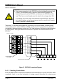
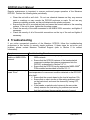
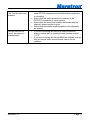
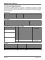
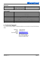
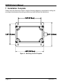
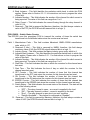
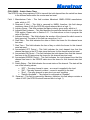
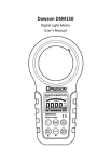
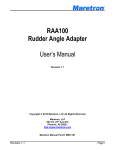
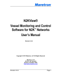
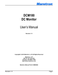
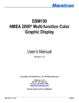
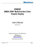
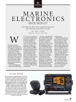
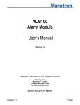
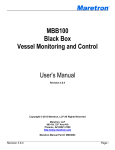
DCR100 DC Relay Module User’s Manual Revision 1.2 Copyright ©2014 Maretron, LLP All Rights Reserved Maretron, LLP 9014 N. 23rd Ave #10 Phoenix, AZ 85021-7850 http://www.maretron.com Maretron Manual Part #: M003001 Revision 1.2 Page i DCR100 User's Manual Revision History Revision Description 1.0 Original document 1.1 Added cautions about using red Loctite and acetone cleaners Clarified fuse requirements on installation wiring diagrams 1.2 Added information about configuring channels as annunciators Added environmental specifications Added information about hardware timers and counters Added information about annunciator operating mode Updated configuration section to reflect new configurable parameters Page ii Revision 1.2 Table of Contents 1 Introduction ...........................................................................................................................1 1.1 Firmware Revision .................................................................................................... 1 1.2 DCR100 Features..................................................................................................... 1 1.3 Quick Install .............................................................................................................. 2 1.4 Theory of Operation.................................................................................................. 2 2 Installation .............................................................................................................................3 2.1 Unpacking the Box ................................................................................................... 3 2.2 Choosing a Mounting Location ................................................................................. 3 2.3 Mounting the DCR100 .............................................................................................. 4 2.4 Connecting the DCR100........................................................................................... 4 2.4.1 NMEA 2000® Connection............................................................................... 4 2.4.2 Switched Power Connections ........................................................................ 5 2.4.2.1 Protection ......................................................................................... 6 2.4.3 Checking Connections ................................................................................... 6 2.5 Configuring the DCR100 .......................................................................................... 7 2.5.1 Advanced Configuration… ............................................................................. 7 2.5.1.1 Current Sensor Zero Offset Calibration ............................................ 7 2.5.1.2 Device Instance................................................................................ 7 2.5.1.3 NMEA 2000® PGN Enable/Disable .................................................. 7 2.5.1.4 Restore Factory Defaults ................................................................. 7 2.5.2 Device Label .................................................................................................. 8 2.5.3 Instance ......................................................................................................... 8 2.5.4 Switch Control................................................................................................ 8 2.5.5 Switch Label .................................................................................................. 9 3 Maintenance ..........................................................................................................................9 4 Troubleshooting .................................................................................................................. 10 5 Technical Specifications ...................................................................................................... 12 6 Technical Support ............................................................................................................... 13 7 Installation Template ........................................................................................................... 14 8 Maretron (2 Year) Limited Warranty .................................................................................... 15 Table of Figures Figure 1 – Mounting the DCR100 .............................................................................................. 4 Figure 2 – NMEA 2000® Connector Face Views ....................................................................... 5 Figure 3 – DCR100 Connection Diagram .................................................................................. 6 Figure 4 – Mounting Surface Template ................................................................................... 14 Table of Appendices Appendix A – NMEA 2000® Interfacing.................................................................................... A1 Revision 1.2 Page iii DCR100 User's Manual This page intentionally left blank Page iv Revision 1.2 1 Introduction Congratulations on your purchase of the Maretron DC Relay Module. Maretron has designed and built your DCR100 to the highest standards for years of dependable and accurate service. Maretron's DCR100 contains 6 Direct Current (DC) relays, each capable of switching up to 10 Amps. The DCR100 connects directly to an NMEA 2000® network, so you can turn on and off the relays from a Maretron DSM150 or DSM250 display or any device running Maretron’s N2KView® software. The DCR100 easily handles resistive DC loads like lights, or inductive DC loads like pumps and motors. The DCR100 can also be used to switch AC circuits using external relays. An added benefit of the DCR100 is that it reports the current through each of the six channels. This allows you to determine if loads are drawing too little electrical current such as burnt out bulbs, or if the loads are starting to draw too much electrical current. The DCR100 may also be used to connect annunciators, such as horns or lights, to an NMEA 2000 network for use with N2KView® alerts. The Maretron DCR100 is designed to operate within the harsh demands of the marine environment. However, no piece of marine electronic equipment can function properly unless installed, configured, and maintained in the correct manner. Please read carefully and follow these instructions for installation, configuration, and usage of the Maretron DCR100 in order to ensure optimal performance. 1.1 Firmware Revision This manual corresponds to DCR100 firmware revision 1.1.2.3. 1.2 DCR100 Features The Maretron DCR100 has the following features. NMEA 2000® Interface Waterproof Connectors Sealed Waterproof Enclosure Opto-Isolated from NMEA 2000® Eliminating Potential Ground Loops Six Relays for On / Off Control Over NMEA 2000® Network Each Relay Capable of Carrying Up to 10 Amps Individual Relay Electrical Current Monitoring Relays can have power up states defined (ON, OFF, or Previous states) Relays can be locked against inadvertent actuation Hardware Counters for Each Relay (ON, OFF, and ERROR states) Hardware Timers for Each Relay (ON, OFF, and ERROR states) Automatic Relay Over Current Shutdown (Shuts Down at ≈ 12 Amps) Automatic Relay Thermal Shutdown (Over Temperature Protection) Channels can operate as annunciators for using external lights, horns, etc. for alert notification Revision 1.2 Page 1 DCR100 User's Manual 1.3 Quick Install Installing the Maretron DCR100 involves the following five steps. Please refer to the individual sections for additional details. 1. 2. 3. 4. 5. Unpack the box (Section 2.1) Choose a mounting location (Section 2.2) Mount the DCR100 (Section 2.3) Connect the DCR100 (Section 2.4) Configure the DCR100 (Section 2.5) 1.4 Theory of Operation The DCR100 provides the ability to turn on or off DC power to a load circuit using 6 independent, isolated solid state relays. The DCR100 is a solid state relay, not a circuit protection device. Each channel contains protection against overcurrent, over temperature, and short circuit. These protections are intended to protect the DCR100, and not the load or the associated wires. Each power source supplying power to a device which is controlled by the DCR100 must be individually protected by a circuit breaker. The circuit breaker must be sized appropriately for the size of the wire from the circuit breaker to the DCR100 and from the DCR100 to the load device. In addition, the circuit breaker must be no larger than 10A. Each channel of the DCR100 may be manually switched on or off using any of the following methods: 1) Maretron’s N2KView® software running on a personal computer*, or 2) Maretron’s N2KView® software running on a Maretron MBB100 or MBB200C Black Box for Vessel Monitoring and Control*, or 3) Maretron’s N2KView® software running on a Maretron DSM800, TSM800C, or TSM1330C Vessel Monitoring and Control Touchscreen Computer, 4) a Maretron DSM150 or DSM250 NMEA 2000® Multi-function Color Graphic Display, or 5) an Android or iOS tablet or phone running N2KView Mobile* The switches can be monitored and/or controlled through use of the Breaker/Switch component in the Electrical Distribution category of the Maretron display products listed above. In addition, the current through each channel may be monitored through the Breaker/Switch Current component in the Electrical Distribution category of Maretron display products. Since the channels are solid state relays, if the NMEA 2000 power is removed, all switches will revert to the open (OFF) state. The state that the switch will be in when the NMEA 2000 power is restored can be configured to be ON, OFF, or in the last state the switch was in before power was removed. Each channel has a hardware timer, which accumulates the elapsed time that channel is in the ON, OFF, and ERROR states. Also, each channel has a hardware counter, which accumulates the number of times that the channel has transitioned info the ON, OFF, and ERROR states. These hardware timers and counters may be viewed and reset using a Maretron display Page 2 Revision 1.2 product or N2KAnalyzer software. If there is a valid system time reference on the network, the DCR100 will record the date and time that the timers or counters were reset. 2 Installation 2.1 Unpacking the Box When unpacking the box containing the Maretron DCR100, you should find the following items: 1 – DCR100 – DC Relay Module 1 – Parts Bag containing 4 Stainless Steel Mounting Screws 1 – DCR100 User’s Manual 1 – Warranty Registration Card If any of these items are missing or damaged, please contact Maretron. 2.2 Choosing a Mounting Location Please consider the following when choosing a mounting location. 1. The DCR100 is waterproof, so it can be mounted in a damp or dry location. 2. The orientation is not important, so the DCR100 can be mounted on a horizontal deck, vertical bulkhead, or upside down if desired. 3. The DCR100 is temperature-rated to 55°C (130°F), so it should be mounted away from engines or engine rooms where the operating temperature exceeds the specified limit. Revision 1.2 Page 3 DCR100 User's Manual 2.3 Mounting the DCR100 Attach the DCR100 securely to the vessel using the included stainless steel mounting screws or other fasteners as shown in Figure 1 below. Do not use threadlocking compounds containing methacrylate ester, such as Loctite Red (271), as they will cause stress cracking of the plastic enclosure. Figure 1 – Mounting the DCR100 2.4 Connecting the DCR100 The DCR100 requires two types of electrical connections: 1) the NMEA 2000® connection (refer to Section 2.4.1), and 2) the switched power connections, which are described in Section 2.4.2. 2.4.1 NMEA 2000® Connection The NMEA 2000® connector can be found on the side of the enclosure. The NMEA 2000® connector is a round five pin male connector (see Figure 2). You connect the DCR100 to an NMEA 2000® network using a Maretron NMEA 2000® cable (or compatible cable) by connecting the female end of the cable to the DCR100 (note the key on the male connector and keyway on the female connector). Be sure the cable is connected securely and that the collar on the cable connector is tightened firmly. Connect the other end of the cable (male) to the NMEA 2000® network in the same manner. The DCR100 is designed such that you can plug or unplug it from an NMEA 2000® network while the power to the network is connected or disconnected. Please follow recommended practices for installing NMEA 2000® network products. Page 4 Revision 1.2 Figure 2 – NMEA 2000® Connector Face Views 2.4.2 Switched Power Connections The DCR100 switched power connections are made by connecting to the 12-pin terminal strip on the top of the unit. First, remove the four screws at the corners of the unit detaching the splash guard from the unit. On the bottom of the splash guard, you will find a label detailing the wire connection to pin number assignments, which are repeated in the table below. Pin # 1 2 3 4 5 6 7 8 9 10 11 12 Signal Name P1 L1 P2 L2 P3 L3 P4 L4 P5 L5 P6 L6 Revision 1.2 Connection Channel #1 Power Channel #1 Load Channel #2 Power Channel #2 Load Channel #3 Power Channel #3 Load Channel #4 Power Channel #4 Load Channel #5 Power Channel #5 Load Channel #6 Power Channel #6 Load Page 5 DCR100 User's Manual 2.4.2.1 Protection WARNING Each power connection to the DCR100 must be individually protected with a fuse or circuit breaker which is sized to match the wire between the breaker/fuse panel and the DCR100, and between the DCR100 and the load. This fuse or circuit breaker must be sized to be no larger than 10A. For example, if you are using all six channels of the DCR100, there must be 6 circuit breakers and a separate power lead from each circuit breaker to the Px terminal for each channel. The power “Px” terminals must always be connected to the circuit-breaker protected power source (which can be wither 12VDC or 24VDC), and the load “Lx” terminals must always be connected to the power terminal on the load. The other terminal of the load must be connected to vessel ground. This figure shows the connection of a power and load connections to the DCR100. +12VDC or +24VDC 1 2 3 4 5 6 7 8 9 10 11 12 P1 L1 P2 L2 P3 L3 P4 L4 P5 L5 P6 L6 Load Load Load Load Load Load Circuit Breakers (10A MAX) DCR100 Screw Terminals Figure 3 – DCR100 Connection Diagram 2.4.3 Checking Connections Once the NMEA 2000® connection and switched load connection(s) to the DCR100 have been completed, check to see that information is being properly transmitted by observing an Page 6 Revision 1.2 appropriate NMEA 2000® display. If you don’t see channel on/off status, refer to Section 4, “Troubleshooting”. 2.5 Configuring the DCR100 The DCR100 will transmit data over the NMEA 2000 network as it is shipped from the factory; however, it may require configuration, depending on the type of switch monitored. There are several configurable items within the DCR100, which are detailed in the remainder of this section. You configure the ACM100 using Maretron N2KAnalyzer® software or a Maretron DSM150/DSM250 display or other NMEA 2000® display unit that is capable of configuring the ACM100. Please refer to the Maretron N2KAnalyzer User’s Manual, DSM150 User’s Manual, or DSM250 User’s Manual, as appropriate, for details. 2.5.1 Advanced Configuration… Certain parameters do not normally need to be set in order for normal operation, but are included in an advanced configuration section for use in special situations. 2.5.1.1 Current Sensor Zero Offset Calibration The current sensor readings from each channel may occasionally drift such that you see small positive or negative current readings from a channel even though no current is flowing. If this happens, choose this menu option to calibrate the zero offset for the current sensors for all six channels of the DCR100. Performing this calibration will place all channels into the “OFF” state. 2.5.1.2 Device Instance NMEA 2000® provides a unique device instance for each switch monitoring device on a vessel. This value should be programmed in each DCR100 so that each DCR100 is associated with a unique device instance number. The default instance number is 0, which is used to indicate the first DCR100 that is hooked to the network. Subsequent DCR100s connected to the network would be numbered 1, 2, and so on. 2.5.1.3 Installation Description You can configure the two installation description parameters with any text you wish. Examples include date of installation, location, etc. NMEA 2000 diagnostic tools such as Maretron N2KAnalyzer® can display this information. 2.5.1.4 NMEA 2000® PGN Enable/Disable The DCR100 is capable of transmitting NMEA 2000® messages (or PGNs) associated with monitored switch circuits. You may individually enable or disable each of these messages. You may also change the rate of transmission of each of these messages if desired. 2.5.1.5 Restore Factory Defaults Selecting this configuration option causes all stored parameters in the DCR100 to be reset to the values they contained when the unit was manufactured. Revision 1.2 Page 7 DCR100 User's Manual 2.5.2 Device Label Program this parameter with a text string which identifies this particular DCR100, to allow you to easily distinguish it from other DCR100’s on the network. 2.5.3 Instance Program this parameter with the instance of the switch bank controlled by this DCR100. Each switch bank should be programmed with a unique number. This number is used by a display device to distinguish the switches controlled by this DCR100 from switches controlled by other devices on the network. 2.6 Channel #x… 2.6.1 Label Each channel has a text label you can set to identify the load controlled by that channel (for example, “EXHAUST FAN” or “NAV LIGHTS”). For each channel, set this to a value which describes the load being controlled so that you can easily identify it in display devices. 2.6.2 Operating Mode Each channel can be operated in one of two modes: Normal: the channel operates as a standard NMEA 2000 switch. It can be controlled via N2KView or a DSM150/DSM250 or other NMEA 2000 display with standard NMEA 2000 commands Alert/Annunciator: the channel operates as an annunciator, similar to the Maretron ALM100. This allows you to connect a light, horn, bell, siren, or other warning device to the channel and actuate it from N2KView or a DSM150/DSM250 display in the case of an alert. The remaining configurable parameters differ depending on which operating mode is select for the channel. These are described in the following subsections. 2.6.2.1 Normal Mode Configurable Parameters These items are configurable only when the channel is set to “Normal” mode. 2.6.2.2 Switch Lock For safety critical situations or other situations where you don’t want a switch channel’s state changed, you can use this parameter to set the switch from an “Unlocked” (normal) state, in which is the switch responds normally to commands over the NMEA 2000® network, to a “Locked” state, in which the switch will not change state in response to any commands until it is put back into the “Unlocked” state. You might lock a switch into the OFF state if you are servicing equipment that is powered by that channel, or you might lock a switch into the ON state if the channel powers a circuit whose power must remain on. Page 8 Revision 1.2 2.6.2.3 Power Up State Since the switch channels in the DCR100 are solid state relays, the switch channels will open (OFF state) whenever NMEA 2000® power is removed. This parameter lets you define the state of this switch channel when the DCR100 is powered up through the NMEA 2000® network after it has been powered down. You can chose “ON”, in which case the switch is closed as soon as power is applied; “OFF”, in which case the switch remains open after power is applied; or “Previous”, in which case the switch is set to the state it held before power was removed. 2.6.2.4 Switch Control This menu allows you to see the current state of each switch on the DCR100 (“On”, “Off”, or “Error”). It also allows you to set each switch to the ON or OFF state. Setting the switch to the Off State will clear an Error condition. 2.6.2.5 Reset Counter This will reset the hardware counters for this channel. If a system time is available on the NMEA 2000® network (e.g., from a GPS), the date/time the counters were reset will be recorded as well. 2.6.2.6 Reset Timer This will reset the hardware timers for this channel. If a system time is available on the NMEA 2000® network (e.g., from a GPS), the date/time the timers were reset will be recorded as well. 2.6.2.7 Alert/Annunciator Mode Configurable Parameters These items are configurable only when the channel is set to “Alert/Annunciator” mode. 2.6.2.7.1 Annunciator Instance Program this parameter with an instance for the annunciator. Each annunciator device on the network must have a unique instance number. 2.6.2.7.2 Test Annunciator Select this option to test the operation of the annunciator. Pressing this switch will cause any connected annunciator to emit light or sound. 3 Maintenance WARNING The DCR100 DC Relay Module is operated under remote control. Before servicing any load device connected to the DCR100, you must first disconnect the wire between the DCR100 load terminal and the load device. Failure to do so can result in serious bodily harm. Revision 1.2 Page 9 DCR100 User's Manual Regular maintenance is important to ensure continued proper operation of the Maretron DCR100. Perform the following tasks periodically: Clean the unit with a soft cloth. Do not use chemical cleaners as they may remove paint or markings or may corrode the DCR100 enclosure or seals. Do not use any cleaners containing acetone, as they will deteriorate the plastic enclosure. Ensure that the unit is mounted securely and cannot be moved relative to the mounting surface. If the unit is loose, tighten the mounting screws. Check the security of the cable connected to the NMEA 2000® connector, and tighten if necessary. Check the security of all of the switch connections on the top of the unit and tighten if necessary. 4 Troubleshooting If you notice unexpected operation of the Maretron DCR100, follow the troubleshooting procedures in this section to remedy simple problems. If these steps do not solve your problem, please contact Maretron Technical Support (refer to Section 6 for contact information). Symptom No breaker/switch data visible on NMEA 2000® network. A breaker/switch always reads “Error” Page 10 Troubleshooting Procedure Ensure that the DCR100 is properly connected to the NMEA 2000® network. Ensure that the DCR100 instance of the breaker/switch component matches the instance programmed into the DCR100, as described in Section 2.5.1.1. Ensure that the DCR100 has the appropriate NMEA 2000® PGNs enabled as described in Section 2.5.1.1. The DCR100 may have shut down the affected channel due to an overtemperature or overcurrent condition detected on the DCR100 relay itself. Ensure that the current drawn by the load is less than 10A. Ensure that no short circuits or other wiring problems exist on the load circuit, and reset the channel by turning OFF, then ON. If the breaker or switch control returns to the error state, closely examine the load wiring for problems and ensure that the load draws the appropriate amount of current. Revision 1.2 A breaker/switch is “ON”, but the load is not powered. You can see, but not control, the state of a breaker/switch Revision 1.2 Ensure that the load is connected to the load terminal of the same DCR100 channel that the breaker/switch component is controlling. Ensure that the load’s terminal not connected to the DCR100 is connected to vessel ground. Ensure that the connection between the breaker and the channel’s power terminal is good. Ensure that the breaker supplying power to the channel is not tripped. If you are controlling the load via a DSM150/DSM250 display, ensure that it is running at least firmware revision 1.4.10. If you are controlling the load via N2KView software, ensure that you have a switch control license version for the software. Page 11 DCR100 User's Manual 5 Technical Specifications As Maretron is constantly improving its products, all specifications are subject to change without notice. Maretron products are designed to be accurate and reliable; however, they should be used only as aids to navigation and not as a replacement for traditional navigation aids and techniques. Specifications Parameter Maximum DC Switching Current DC Switching Voltage Contact Resistance Current Sense Accuracy Value 10 A <32 VDC <10 mΩ ±100 mA Comment Maximum Current Per Channel Certifications Parameter NMEA 2000® Standard Maritime Navigation and Radiocommunication Equipment & Systems Maritime Navigation and Radiocommunication Equipment & Systems FCC and CE Mark Comment Level A IEC 61162-3 Tested to IEC 60945 Electromagnetic Compatibility NMEA 2000® Parameter Group Numbers (PGNs) Description Periodic Data PGNs PGN # PGN Name 127501 Binary Switch Bank Status Response to Requested PGNs 126464 126996 126998 059392 059904 060928 065240 126208 126720 65284 130836 Protocol PGNs Maretron Proprietary PGNs PGN List (Transmit and Receive) Product Information Configuration Information ISO Acknowledge ISO Request ISO Address Claim ISO Address Command NMEA Configuration DC Relay Current Switch Status Counter 130837 Switch Status Timer Default Rate 1 time / 15 seconds and on switch change N/A N/A N/A N/A N/A N/A N/A N/A N/A 1 time per second 1 time / 15 seconds and on switch change 1 time / 15 seconds Electrical Parameter Operating Voltage Power Consumption Load Equivalence Number (LEN) Reverse Battery Protection Load Dump Protection Page 12 Value 9 to 32 Volts 150 mA 3 Yes Yes Comment DC Voltage NMEA 2000® Interface NMEA 2000® Spec. (1LEN = 50 mA) Indefinitely Energy Rated per SAE J1113 Revision 1.2 Mechanical Parameter Value Comment 3.50” x 4.20” x 2.03” Including Flanges for Mounting (88.9mm x 106.7mm x 51.6mm) 13 oz. (368.5 g) Size Weight Environmental Parameter IEC 60945 Classification Degree of Protection Operating Temperature Storage Temperature Relative Humidity Vibration Solar Radiation Corrosion (Salt Mist) Electromagnetic Emission Electromagnetic Immunity Safety Precautions Value Exposed IP64 -25°C to 55°C -40°C to 70°C 93%RH @40° per IEC60945-8.2 2-13.2Hz @ ±1mm, 13.2-100Hz @ 7m/s2 per IEC 60945-8.7 Ultraviolet B, A, Visible, and Infrared per IEC 60945-8.10 4 times 7days @ 40°C, 95%RH after 2 hour Salt Spray Per IEC 60945-8.12 Conducted and Radiated Emission per IEC 60945-9 Conducted, Radiated, Supply, and ESD per IEC 60945-10 Dangerous Voltage, Electromagnetic Radio Frequency per IEC 60945-12 6 Technical Support If you require technical support for Maretron products, you can reach us in any of the following ways: Telephone: Fax: E-mail: World Wide Web: Mail: Revision 1.2 1-866-550-9100 1-602-861-1777 [email protected] http://www.maretron.com Maretron, LLP Attn: Technical Support 9014 N. 23rd Ave Suite 10 Phoenix, AZ 85021 USA Page 13 DCR100 User's Manual 7 Installation Template Please check the dimensions before using the following diagram as a template for drilling the mounting holes because the printing process may have distorted the dimensions. Figure 4 – Mounting Surface Template Page 14 Revision 1.2 8 Maretron (2 Year) Limited Warranty Maretron warrants the DCR100 to be free from defects in materials and workmanship for two (2) years from the date of original purchase. If within the applicable period any such products shall be proved to Maretron’s satisfaction to fail to meet the above limited warranty, such products shall be repaired or replaced at Maretron’s option. Purchaser's exclusive remedy and Maretron’s sole obligation hereunder, provided product is returned pursuant to the return requirements below, shall be limited to the repair or replacement, at Maretron’s option, of any product not meeting the above limited warranty and which is returned to Maretron; or if Maretron is unable to deliver a replacement that is free from defects in materials or workmanship, Purchaser’s payment for such product will be refunded. Maretron assumes no liability whatsoever for expenses of removing any defective product or part or for installing the repaired product or part or a replacement therefore or for any loss or damage to equipment in connection with which Maretron’s products or parts shall be used. With respect to products not manufactured by Maretron, Maretron’s warranty obligation shall in all respects conform to and be limited to the warranty actually extended to Maretron by its supplier. The foregoing warranties shall not apply with respect to products subjected to negligence, misuse, misapplication, accident, damages by circumstances beyond Maretron’s control, to improper installation, operation, maintenance, or storage, or to other than normal use or service. THE FOREGOING WARRANTIES ARE EXPRESSLY IN LIEU OF AND EXCLUDES ALL OTHER EXPRESS OR IMPLIED WARRANTIES, INCLUDING BUT NOT LIMITED TO THE IMPLIED WARRANTIES OF MERCHANTABILITY AND OF FITNESS FOR A PARTICULAR PURPOSE. Statements made by any person, including representatives of Maretron, which are inconsistent or in conflict with the terms of this Limited Warranty, shall not be binding upon Maretron unless reduced to writing and approved by an officer of Maretron. IN NO CASE WILL MARETRON BE LIABLE FOR INCIDENTAL OR CONSEQUENTIAL DAMAGES, DAMAGES FOR LOSS OF USE, LOSS OF ANTICIPATED PROFITS OR SAVINGS, OR ANY OTHER LOSS INCURRED BECAUSE OF INTERRUPTION OF SERVICE. IN NO EVENT SHALL MARETRON’S AGGREGATE LIABILITY EXCEED THE PURCHASE PRICE OF THE PRODUCT(S) INVOLVED. MARETRON SHALL NOT BE SUBJECT TO ANY OTHER OBLIGATIONS OR LIABILITIES, WHETHER ARISING OUT OF BREACH OF CONTRACT OR WARRANTY, TORT (INCLUDING NEGLIGENCE), OR OTHER THEORIES OF LAW WITH RESPECT TO PRODUCTS SOLD OR SERVICES RENDERED BY MARETRON, OR ANY UNDERTAKINGS, ACTS OR OMISSIONS RELATING THERETO. Maretron does not warrant that the functions contained in any software programs or products will meet purchaser’s requirements or that the operation of the software programs or products will be uninterrupted or error free. Purchaser assumes responsibility for the selection of the software programs or products to achieve the intended results, and for the installation, use and results obtained from said programs or products. No specifications, samples, descriptions, or illustrations provided Maretron to Purchaser, whether directly, in trade literature, brochures or other documentation shall be construed as warranties of any kind, and any failure to conform with such specifications, samples, descriptions, or illustrations shall not constitute any breach of Maretron’s limited warranty. Warranty Return Procedure: To apply for warranty claims, contact Maretron or one of its dealers to describe the problem and determine the appropriate course of action. If a return is necessary, place the product in its original packaging together with proof of purchase and send to an Authorized Maretron Service Location. You are responsible for all shipping and insurance charges. Maretron will return the replaced or repaired product with all shipping and handling prepaid except for requests requiring expedited shipping (i.e. overnight shipments). Failure to follow this warranty return procedure could result in the product’s warranty becoming null and void. Maretron reserves the right to modify or replace, at its sole discretion, without prior notification, the warranty listed above. To obtain a copy of the then current warranty policy, please go to the following web page: http://www.maretron.com/company/warranty.php Revision 1.2 Page 15 DCR100 User's Manual This page intentionally left blank Page xvi Revision 1.2 Appendix A – NMEA 2000® Interfacing DCR100 NMEA 2000® Periodic Data Transmitted PGNs PGN 127501 – Binary Switch Bank Status The DCR100 uses this PGN to transmit the state of each of the connected switch inputs Field 1: Indicator Bank Instance – This field identifies the particular switch bank to which this PGN applies. Please refer to Section 2.5.3 for instructions on how to program the value of this field. 2: Indicator #1 – This field indicates the state of the solid-state relay between the power source connected to P1 terminal and the load connected to the L1 terminal of the DCR100. The state will be one of the following values: “OFF” – The relay channel is open – no current is supplied to the load. “ON” – The relay channel is closed – current is supplied to the load. “Error” – The relay channel is open due to an error condition “Data Not Available” – The channel is configured as “Disabled” 3: Indicator #2 – This field indicates the state of the solid-state relay between the power source connected to P2 terminal and the load connected to the L2 terminal of the DCR100. 4: Indicator #3 – This field indicates the state of the solid-state relay between the power source connected to P3 terminal and the load connected to the L3 terminal of the DCR100. 5: Indicator #4 – This field indicates the state of the solid-state relay between the power source connected to P4 terminal and the load connected to the L4 terminal of the DCR100. 6: Indicator #5 – This field indicates the state of the solid-state relay between the power source connected to P5 terminal and the load connected to the L5 terminal of the DCR100. 7: Indicator #6 – This field indicates the state of the solid-state relay between the power source connected to P6 terminal and the load connected to the L6 terminal of the DCR100. PGN 65284 – DC Relay Current The DCR100 uses this proprietary PGN to transmit the amount of current flowing through each of the relay channels Field 1: Manufacturer Code – This field contains Maretron’s NMEA 2000® manufacturer code, which is 137. 2: Reserved (2 bits) – This field is reserved by NMEA; therefore, this field always contains a value of 0x3 (the DCR100 sets all reserved bits to a logic 1). 3: Industry Group – This field contains the Marine industry group code, which is 4. Revision 1.2 Appendix A – NMEA 2000 Interfacing Page A1 DCR100 User's Manual 4: Bank Instance – This field identifies the particular switch bank to which this PGN applies. Please refer to Section 2.5.1.1 for instructions on how to program the value of this field. 5: Indicator Number – This field indicates the number of the channel for which current is being reported. The value of this field can range from 1 to 6. 6: Relay Current – This field indicates the current flowing through the relay channel in units of 0.1A. 7: Reserved – This field is reserved by Maretron; therefore, this field always contains a value of 0xFFFF (the DCR100 sets all reserved bits to a logic 1). PGN 130836 – Switch Status Counter The DCR100 uses this proprietary PGN to transmit the number of times the switch has transitioned into the different states since the counter was last reset Field 1: Manufacturer Code – This field contains Maretron’s NMEA 2000® manufacturer code, which is 137. 2: Reserved (2 bits) – This field is reserved by NMEA; therefore, this field always contains a value of 0x3 (the DCR100 sets all reserved bits to a logic 1). 3: Industry Group – This field contains the Marine industry group code, which is 4. 4: Indicator Bank Instance – This field identifies the particular switch bank to which this PGN applies. Please refer to Section 2.5.1.1 for instructions on how to program the value of this field. 5: Indicator Number – This field indicates the number of the channel for which current is being reported. The value of this field can range from 1 to 6. 6: Start Date – This field indicates the date on which the counters for this channel were last reset. 7: Start Time – This field indicates the time of day on which the counters for this channel were last reset. 8: OFF Counter – This field indicates the number of times that this channel has transitioned to the OFF state since the counters for this channel were last reset. 9: ON Counter – This field indicates the number of times that this channel has transitioned to the ON state since the counters for this channel were last reset. 10: ERROR Counter – This field indicates the number of times that this channel has transitioned to the ERROR state since the counters for this channel were last reset. 11: Switch Status – This field indicates the current status of the channel. The state will be one of the following values: “OFF” – The relay channel is open – no current is supplied to the load. “ON” – The relay channel is closed – current is supplied to the load. “Error” – The relay channel is open due to an error condition “Data Not Available” – The channel is configured as “Disabled” 12: Reserved – This field is reserved by Maretron; therefore, this field always contains a value of 0x3F (the DCR100 sets all reserved bits to a logic 1). Page A2 Appendix A – NMEA 2000 Interfacing Revision 1.2 PGN 130836 – Switch Status Timer The DCR100 uses this proprietary PGN to transmit the total elapsed time the switch has been in the different states since the counter was last reset. Field 1: Manufacturer Code – This field contains Maretron’s NMEA 2000® manufacturer code, which is 137. 2: Reserved (2 bits) – This field is reserved by NMEA; therefore, this field always contains a value of 0x3 (the DCR100 sets all reserved bits to a logic 1). 3: Industry Group – This field contains the Marine industry group code, which is 4. 4: Indicator Bank Instance – This field identifies the particular switch bank to which this PGN applies. Please refer to Section 2.5.1.1 for instructions on how to program the value of this field. 5: Indicator Number – This field indicates the number of the channel for which current is being reported. The value of this field can range from 1 to 6. 6: Start Date – This field indicates the date on which the timers for this channel were last reset. 7: Start Time – This field indicates the time of day on which the timers for this channel were last reset. 8: Accumulated OFF Period – This field indicates the total elapsed time that this channel has been in the OFF state since the timers for this channel were last reset. 9: Accumulated ON Period – This field indicates the total elapsed time that this channel has been in the ON state since the timers for this channel were last reset. 10: Accumulated ERROR Period – This field indicates the total elapsed time that this channel has been in the ERROR state since the timers for this channel were last reset . 11: Switch Status – This field indicates the current status of the channel. The state will be one of the following values: “OFF” – The relay channel is open – no current is supplied to the load. “ON” – The relay channel is closed – current is supplied to the load. “Error” – The relay channel is open due to an error condition “Data Not Available” – The channel is configured as “Disabled” 12: Reserved – This field is reserved by Maretron; therefore, this field always contains a value of 0x3F (the DCR100 sets all reserved bits to a logic 1). Revision 1.2 Appendix A – NMEA 2000 Interfacing Page A3