1
______________________________________________________________________________ High-Performance Pan-Tilt Unit (E Series) VERSION: 4.10 REVISION DATE: December, 2011 Command Reference Manual E Series Command Reference Manual DOCUMENT CONTROL Date 09/2010 Author A. Hernandez Rev. # 4.00 Changes Initial E Series release 12/2011 A. Hernandez 4.10 Updated E Series release COPYRIGHT NOTICE Pan-Tilt Unit E Series Command Reference Manual ©1991, 2011 by FLIR Motion Control Systems, Inc., 890C Cowan Road, Burlingame, California 94010, (650)692-3900, FAX: (650)692-3930, www.FLIR.com./MCS All rights reserved. Protected under numerous U.S. patents, including 5463432 and 580241 with other patents pending. No part of this book may be reproduced, stored in a retrieval system, or transcribed in any form or by any means including but not limited to electronic, mechanical, photocopying, recording, or otherwise, without the prior written permission of FLIR Motion Control Systems, Inc. The information in this manual is subject to change without notice and, except for the warranty, does not represent a commitment on the part of FLIR Motion Control Systems, Inc. FLIR Motion Control Systems, Inc. cannot be held liable for any mistakes in this manual and reserves the right to make changes. Table of Contents 1 - Introduction ............................................................................................... 1 1.1 1.2 1.3 – Safety ......................................................................................................................... 1 – E Series Features ....................................................................................................... 1 – About This Manual..................................................................................................... 2 1.3.1 – Formatting Conventions..................................................................................................... 2 2 – Getting Started .......................................................................................... 5 2.1 2.2 2.3 2.4 – ASCII Command Syntax .............................................................................................. 5 – Power Levels .............................................................................................................. 6 – Acceleration ............................................................................................................... 6 – Serial Command List .................................................................................................. 7 2.4.1 – Position............................................................................................................................... 7 2.4.2 – Speed .................................................................................................................................. 7 2.4.3 – Continuous Axis Rotation ................................................................................................... 7 2.4.4 – Limits .................................................................................................................................. 8 2.4.5 – Unit Controls ...................................................................................................................... 8 2.4.6 – Power ................................................................................................................................. 8 2.4.7 – Serial & Expanded I/O ........................................................................................................ 9 2.4.8 – Step Modes ........................................................................................................................ 9 2.4.9 – IP Network .......................................................................................................................... 9 2.4.10 – Control Mode ..................................................................................................................... 9 3 – Position ................................................................................................... 11 3.1 – Absolute Position ..................................................................................................... 11 3.1.1 3.1.2 3.1.3 3.1.4 3.2 – Offset Position ......................................................................................................... 12 3.2.1 3.2.2 3.2.3 3.2.4 3.3 – Commands ....................................................................................................................... 12 – Syntax ............................................................................................................................... 12 – Example ............................................................................................................................ 12 – See Also ............................................................................................................................ 12 – Resolution per Position............................................................................................ 13 3.3.1 3.3.2 3.3.3 3.3.4 3.4 – Commands ....................................................................................................................... 11 – Syntax ............................................................................................................................... 11 – Example ............................................................................................................................ 11 – See Also ............................................................................................................................ 11 – Commands ....................................................................................................................... 13 – Syntax ............................................................................................................................... 13 – Example ............................................................................................................................ 13 – See Also ............................................................................................................................ 13 – Limit Position Queries.............................................................................................. 13 3.4.1 – Commands ....................................................................................................................... 14 3.4.2 – Syntax ............................................................................................................................... 14 3.4.3 – Example ............................................................................................................................ 14 E Series Command Reference Manual 3.4.4 – See Also ............................................................................................................................ 14 3.5 – Position Limit Enforcement ..................................................................................... 14 3.5.1 3.5.2 3.5.3 3.5.4 3.6 – Commands ....................................................................................................................... 15 – Syntax ............................................................................................................................... 15 – Example ............................................................................................................................ 15 – See Also ............................................................................................................................ 15 –Position Execution Mode .......................................................................................... 16 3.6.1 – Commands ....................................................................................................................... 16 3.6.2 – Syntax ............................................................................................................................... 16 3.6.3 – Example ............................................................................................................................ 16 3.7 – Await Position Completion ...................................................................................... 17 3.7.1 3.7.2 3.7.3 3.7.4 3.8 – Commands ....................................................................................................................... 17 – Syntax ............................................................................................................................... 17 – Example ............................................................................................................................ 17 – See Also ............................................................................................................................ 17 – Halt........................................................................................................................... 17 3.8.1 3.8.2 3.8.3 3.8.4 3.9 – Commands ....................................................................................................................... 17 – Syntax ............................................................................................................................... 18 – Example ............................................................................................................................ 18 – See Also ............................................................................................................................ 18 – Monitor (Auto-scan) ................................................................................................ 18 3.9.1 3.9.2 3.9.3 3.9.4 3.10 – Commands ....................................................................................................................... 18 – Syntax ............................................................................................................................... 19 – Example ............................................................................................................................ 19 – See Also ............................................................................................................................ 19 – Position Presets ....................................................................................................... 20 3.10.1 – Commands ....................................................................................................................... 20 3.10.2 – Syntax ............................................................................................................................... 20 3.10.3 – Example ............................................................................................................................ 20 3.11 – Query/Set PTU Speed/Position ............................................................................... 21 3.11.1 – Commands ....................................................................................................................... 21 3.11.2 – Syntax ............................................................................................................................... 21 3.11.3 – Example ............................................................................................................................ 21 4 – Speed Control .......................................................................................... 23 4.1 – Absolute Speed ........................................................................................................ 24 4.1.1 4.1.2 4.1.3 4.1.4 4.2 – Relative Speed ......................................................................................................... 25 4.2.1 4.2.2 4.2.3 4.2.4 4.3 – Commands ....................................................................................................................... 24 – Syntax ............................................................................................................................... 24 – Example ............................................................................................................................ 24 – See Also ............................................................................................................................ 25 – Commands ....................................................................................................................... 25 – Syntax ............................................................................................................................... 25 – Example ............................................................................................................................ 25 – See Also ............................................................................................................................ 25 – Acceleration ............................................................................................................. 26 4.3.1 – Commands ....................................................................................................................... 26 Table of Contents 4.3.2 – Syntax ............................................................................................................................... 26 4.3.3 – Example ............................................................................................................................ 26 4.3.4 – See Also ............................................................................................................................ 26 4.4 – Base (Start-Up) Speed .............................................................................................. 27 4.4.1 4.4.2 4.4.3 4.4.4 4.5 – Speed Bounds .......................................................................................................... 28 4.5.1 4.5.2 4.5.3 4.5.4 4.6 – Commands ....................................................................................................................... 28 – Syntax ............................................................................................................................... 28 – Example ............................................................................................................................ 28 – See Also ............................................................................................................................ 28 – Speed Control Modes .............................................................................................. 29 4.6.1 4.6.2 4.6.3 4.6.4 5 – Commands ....................................................................................................................... 27 – Syntax ............................................................................................................................... 27 – Example ............................................................................................................................ 27 – See Also ............................................................................................................................ 27 – Commands ....................................................................................................................... 29 – Syntax ............................................................................................................................... 29 – Example ............................................................................................................................ 30 – See Also ............................................................................................................................ 30 – Continuous Axis Rotation ........................................................................ 31 5.1 – Continuous Rotation ................................................................................................ 31 5.1.1 – Commands ....................................................................................................................... 31 5.1.2 – Syntax ............................................................................................................................... 31 5.1.3 – Example ............................................................................................................................ 32 6 – User Defined Limits ................................................................................. 33 6.1 – Position Limit Queries .............................................................................................. 33 6.1.1 6.1.2 6.1.3 6.1.4 6.2 – Position Limit Enforcement ..................................................................................... 35 6.2.1 6.2.2 6.2.3 6.2.4 7 – Commands ....................................................................................................................... 33 – Syntax ............................................................................................................................... 34 – Example ............................................................................................................................ 34 – See Also ............................................................................................................................ 35 – Commands ....................................................................................................................... 35 – Syntax ............................................................................................................................... 36 – Example ............................................................................................................................ 36 – See Also ............................................................................................................................ 36 – Unit Commands ....................................................................................... 37 7.1 – Reset PTU ................................................................................................................. 37 7.1.1 – Commands ....................................................................................................................... 37 7.1.2 – Syntax ............................................................................................................................... 37 7.1.3 – Example ............................................................................................................................ 38 7.2 – Default Save/Restore ............................................................................................... 38 7.2.1 – Commands ....................................................................................................................... 39 7.2.2 – Syntax ............................................................................................................................... 39 7.3 – Echo ......................................................................................................................... 39 7.3.1 – Commands ....................................................................................................................... 39 7.3.2 – Syntax ............................................................................................................................... 39 E Series Command Reference Manual 7.3.3 – Example ............................................................................................................................ 40 7.4 – Feedback .................................................................................................................. 40 7.4.1 – Commands ....................................................................................................................... 40 7.4.2 – Syntax ............................................................................................................................... 40 7.4.3 – Example ............................................................................................................................ 40 7.5 – Controller Firmware Version ................................................................................... 40 7.5.1 – Commands ....................................................................................................................... 41 7.5.2 – Syntax ............................................................................................................................... 41 7.5.3 – Example ............................................................................................................................ 41 7.6 – Voltage and Temperature Query ............................................................................. 41 7.6.1 – Commands ....................................................................................................................... 41 7.6.2 – Syntax ............................................................................................................................... 41 7.6.3 – Example ............................................................................................................................ 41 8 – Power Control ......................................................................................... 43 8.1 – Hold Power Mode .................................................................................................... 43 8.1.1 – Commands ....................................................................................................................... 43 8.1.2 – Syntax ............................................................................................................................... 44 8.1.3 – Example ............................................................................................................................ 44 8.2 – In-Motion Power Mode ........................................................................................... 44 8.2.1 – Commands ....................................................................................................................... 44 8.2.2 – Syntax ............................................................................................................................... 45 8.2.3 – Example ............................................................................................................................ 45 9 – Host Serial Port ........................................................................................ 47 9.1 – Baud Rate ................................................................................................................. 47 9.1.1 9.1.2 9.1.3 9.1.4 – Commands ....................................................................................................................... 47 – Syntax ............................................................................................................................... 47 – Example ............................................................................................................................ 48 – See Also ............................................................................................................................ 48 10 – Expanded I/O........................................................................................... 49 10.1 – Serial Communications Target................................................................................. 49 10.1.1 – Commands ....................................................................................................................... 49 10.1.2 – Syntax ............................................................................................................................... 49 10.1.3 – Example ............................................................................................................................ 50 10.1.4 – See Also ............................................................................................................................ 50 10.2 – Expanded Serial Port................................................................................................ 50 10.2.1 – Commands ....................................................................................................................... 50 10.2.2 – Syntax ............................................................................................................................... 51 10.2.3 – Example ............................................................................................................................ 51 10.2.4 – See Also ............................................................................................................................ 51 10.3 – ASCII TTL Control ..................................................................................................... 52 10.3.1 – Commands ....................................................................................................................... 52 10.3.2 – Syntax .............................................................................................................................. 52 10.3.3 – Example ............................................................................................................................ 52 11 – Step Modes ............................................................................................. 53 Table of Contents 11.1 – Configuring Step Mode ............................................................................................ 53 11.1.1 – Commands ....................................................................................................................... 53 11.1.2 – Syntax ............................................................................................................................... 53 11.1.3 – Example ............................................................................................................................ 53 12 – PTU Serial Networks ................................................................................ 55 12.1 – Unit Network ID ....................................................................................................... 55 12.1.1 – Commands ....................................................................................................................... 55 12.1.2 – Syntax ............................................................................................................................... 55 12.1.3 – Example ............................................................................................................................ 55 12.1.4 – See Also ............................................................................................................................ 55 12.2 – Unit Select/Deselect ................................................................................................ 56 12.2.1 – Commands ....................................................................................................................... 56 12.2.2 – Syntax ............................................................................................................................... 56 12.2.3 – Example ............................................................................................................................ 56 12.2.4 – See Also ............................................................................................................................ 56 13 – IP Network .............................................................................................. 57 13.1 – MAC Address ........................................................................................................... 57 13.1.1 – Commands ....................................................................................................................... 57 13.1.2 – Syntax ............................................................................................................................... 57 13.1.3 – Example ............................................................................................................................ 57 13.2 – IP Address ................................................................................................................ 58 13.2.1 – Commands ....................................................................................................................... 58 13.2.2 – Syntax ............................................................................................................................... 58 13.2.3 – Example ............................................................................................................................ 58 13.3 – Network Mode ......................................................................................................... 58 13.3.1 – Commands ....................................................................................................................... 58 13.3.2 – Syntax ............................................................................................................................... 58 13.3.3 – Example ............................................................................................................................ 59 13.4 – Redirect Port ............................................................................................................ 59 13.4.1 – Command ......................................................................................................................... 59 13.4.2 – Syntax ............................................................................................................................... 59 13.4.3 – Example ............................................................................................................................ 59 13.5 – Network Host Name ................................................................................................ 59 13.5.1 – Commands ....................................................................................................................... 59 13.5.2 – Syntax ............................................................................................................................... 59 13.5.3 – Example ............................................................................................................................ 60 13.6 – Network Mask.......................................................................................................... 60 13.6.1 – Commands ....................................................................................................................... 60 13.6.2 – Syntax ............................................................................................................................... 60 13.6.3 – Example ............................................................................................................................ 60 14 – Control Modes ......................................................................................... 61 14.1 14.2 14.3 – Commands ............................................................................................................... 62 – Syntax....................................................................................................................... 62 – Example ................................................................................................................... 62 E Series Command Reference Manual 15 – E Series TCP/IP Control ............................................................................ 63 15.1 – Using TCP/IP Control................................................................................................ 63 15.1.1 – Legacy Applications .......................................................................................................... 64 15.1.2 – Using HyperTerminal ........................................................................................................ 64 15.1.3 – Using Tera Term ............................................................................................................... 64 15.1.4 – Using Putty ....................................................................................................................... 65 16 – Pelco D Protocol ...................................................................................... 67 16.1 – Configuration ........................................................................................................... 67 16.1.1 – Commands ....................................................................................................................... 67 16.1.2 – Syntax ............................................................................................................................... 67 16.1.3 – Example ............................................................................................................................ 67 16.2 16.3 16.4 – Standard Pelco D Commands .................................................................................. 68 – Extended Pelco D Commands .................................................................................. 68 – Auxiliary Pelco D IDs ................................................................................................ 69 A – TCP/IP Firewall............................................................................................ 71 A.1 – Rules............................................................................................................................... 71 A.1.1 – Rule Syntax ........................................................................................................................ 71 A.1.2 – Examples ............................................................................................................................ 72 A.2 – Management.................................................................................................................. 72 A.2.1 – Rule Lists ............................................................................................................................ 73 A.2.2 – Managing Rule Lists ........................................................................................................... 74 A.3 – Using the Firewall .......................................................................................................... 74 A.3.1 – Commands ......................................................................................................................... 74 A.3.2 – Syntax................................................................................................................................. 74 A.4 – Precautions .................................................................................................................... 74 A.4.1 – HTTP ................................................................................................................................... 74 A.4.2 – DHCP .................................................................................................................................. 75 A.4.3 – TCP Control ........................................................................................................................ 75 A.5 – Example Configurations ................................................................................................. 75 A.5.1 – Block Everything ................................................................................................................ 75 A.5.2 – Block Everything Except DHCP ........................................................................................... 75 A.5.3 – HTTP Only .......................................................................................................................... 75 A.5.4 – TCP/IP Control.................................................................................................................... 75 A.5.5 – Listing Rules ....................................................................................................................... 76 B – Compatibility Mode ................................................................................. 77 B.1 – Commands ..................................................................................................................... 77 B.2 – Syntax ............................................................................................................................. 77 B.3 – Effects............................................................................................................................. 77 B.3.1 – Firmware Version 3.0.0 ...................................................................................................... 77 B.3.2 – Firmware Version 3.1.4 and Later...................................................................................... 78 Table of Contents C – Timestamps ............................................................................................. 79 C.1 – Commands ..................................................................................................................... 79 C.2 – Syntax ............................................................................................................................. 79 C.3 – Example .......................................................................................................................... 79 E Series Command Reference Manual This page intentionally left blank. 1 - Introduction Each Pan-Tilt Unit (PTU) from FLIR Motion Control Systems, Inc. includes a comprehensive set of available commands that give you full control over all functionality. The E Series of PTUs features an expanded command set for even more control options. This Pan-Tilt E Series Command Reference Manual covers the software control interface for the following E Series PTUs: • PTU-D48 E Series • PTU-D100 E Series • PTU-D300 E Series Each PTU also includes a User Manual specific to that unit model (such as PTU-D48 E Series User Manual). The User Manual describes the electrical and mechanical interfaces and includes general setup and use instructions. The E Series command set described in this manual is backwards compatible with prior PTU models with the following exceptions: • Range of motion command syntax has been updated (Section 6). • Network commands have been added to support the Ethernet interface (Section 13). Note: This manual is not intended for use with the PTU-D46 or PTU-D47. If you have a PTU-D46 or PTU-D47, please refer to the PTU-D46.47 Command Reference Manual. Note: The Compatibility Mode feature allows you to switch from D Series compatibility to the slightly different E Series behavior. Please see Appendix B for details. 1.1 – Safety Please refer to and comply with all safety warnings contained in your PTU User Manual. 1.2 – E Series Features E The E Series of PTUs includes the following new features: • Built-in Ethernet/Web IP interface for easy configuration, control, and diagnostics • Improved power protection circuitry • 32-pin base connector for simplified wiring • Integrated digital encoder for more robust positioning 1 E Series Command Reference Manual • Programmable ranges of motion • Higher command rates with lower latency and jitter • Reduced calibration movement • Support for future integrated geo-pointing (GPM) and stabilization (ISM) functionality without the need for external hardware • Full backward compatibility with previous PTU models 1.3 – About This Manual This section describes the formatting conventions and information contained in this manual. 1.3.1 – Formatting Conventions This manual uses several formatting conventions to present information of special importance. Commands and other information that is new for the E Series PTUs include the “E” icon shown here. E Lists of items, points to consider, or procedures that do not need to be performed in a specific order appear in bullet format: • Item 1 • Item 2 Procedures that must be followed in a specific order appear in numbered steps: Perform this step first. Perform this step second. Specific keyboard keys are depicted in square brackets and are capitalized, for example: [ESC]. If more than one key should be pressed simultaneously, the notation will appear as [KEY1]+[KEY 2], for example [ALT]+[F4]. Interface elements such as document titles, fields, windows, tabs, buttons, commands, options, and icons appear in bold text. Menus and submenus have the notation Menu>Submenu. For example, “Select File>Save” means that you should first open the File menu, and then select the Save option. Specific commands appear in standard Courier font. Sequences of commands appear in the order in which you should execute them and include horizontal or vertical spaces between commands. This manual also contains important safety information and instructions in specially formatted callouts with accompanying graphic symbols. These callouts and their symbols appear as follows throughout the manual: 2 Introduction WARNING: WARNINGS ALERT YOU TO THE POSSIBILITY OF PERSONAL INJURY OR DEATH IF THESE INSTRUCTIONS ARE NOT FOLLOWED. CAUTION: CAUTIONS ALERT YOU TO THE POSSIBILITY OF EQUIPMENT OR PROPERTY DAMAGE IF THESE INSTRUCTIONS ARE NOT FOLLOWED. Note: Notes provide helpful information. 3 E Series Command Reference Manual This page intentionally left blank. 4 2 – Getting Started This chapter describes the ASCII command syntax used when controlling a PTU via a serial connection, lists the available commands, and discusses power level and acceleration considerations. Please also refer to the “Quick Start” section in your PTU User Manual for information about getting your PTU up and running quickly. 2.1 – ASCII Command Syntax A PTU uses both commands and queries. A command tells the PTU to do something (such as pan to a specific angle). A query asks the PTU to return the requested value (such as reporting the current pan angle). The basic ASCII command syntax is <command><parameter><delimiter>, where: • <command> is the actual command (such as PP for pan position), • <parameter> is an alphanumeric value (such as the desired pan position), and • <delimiter> is a character used to denote the end of a command. Valid delimiter characters can be either [SPACE] or [ENTER]. The basic ASCII query syntax is <command><delimiter>, where: • <command> is the actual command (such as PP for pan position), • <delimiter> is a character used to denote the end of a query. Valid delimiter characters can be either [SPACE] or [ENTER]. For example: • Command: PP<position><delim> sets the desired absolute pan position. • Query: PP<delim> returns the current absolute pan position. Commands and queries return results that display on the terminal screen, as follows: • A successfully executed command displays * <CR><N> on the terminal screen (where <CR> is a carriage return and <N> is a new line). • A successfully executed query displays * <QueryResult><CR><N> (where <QueryResult> is the result of the query you just executed). • A failed command displays ! <ErrorMessage><CR><N> (where <ErrorMessage> describes the error encountered). • A pan axis limit hit asynchronously displays !P. • A tilt axis limit hit asynchronously displays !T. 5 E Series Command Reference Manual Note: You may see one or multiple !P or !T errors. This is normal behavior. This sample command sequence pans the PTU to the left, waits, and then pans it back to the right with queries after finishing each pan movement: PP-2500 * A * PP * Current Pan position is -2500 PP2500 * A * PP * Current Pan position is 2500 2.2 – Power Levels Each FLIR PTU model can accept power within a permissible range of voltages. The ability of any PTU to successfully move the payload depends upon the inertial payload factors and their relationship to power supply voltage, unit speed, acceleration, position, motor torque, etc. In general, higher voltages allow the PTU to handle heavier payloads. Your specific installation will determine the amount of voltage available to the PTU. You may then control how the PTU uses the available power for each axis when the payload is at rest (hold power) or in motion (move power) by specifying High, Regular, or Low power mode. Please refer to: • Section 8.2 for information on setting the PTU move power. • Section 8.1 for information on setting the PTU hold power. Please also refer to your PTU User Manual and Configuration Guide for more information about permissible payload and power voltage ranges. 2.3 – Acceleration You may also control the PTU acceleration. In general, lower acceleration settings place lower torque requirements on the PTU and mounting and allow heavier payloads to be mounted. Acceleration is measured in positions per second per second. Please see Section 4.3 for more information about setting acceleration. 6 Getting Started 2.4 – Serial Command List These tables list the available serial commands. Please refer to later sections within this manual for complete information about the available commands and their usage. 2.4.1 – Position The available position commands are: CMD DESCRIPTION CMD DESCRIPTION CMD DESCRIPTION PP Set/query pan position XS Set preset I Immed. execution mode TP Set/query tilt position XG Go to preset S Slaved mode PO Set/query pan offset XC Clear preset H Halt all TO Set/query tilt offset M Monitor HP Halt pan PR Pan resolution ME Monitor auto enable HT Halt tilt TR Tilt resolution MD Monitor auto disable A Await MQ Monitor auto query Please see Section 3 for more information about the position commands. 2.4.2 – Speed The available speed commands are: CMD DESCRIPTION CMD DESCRIPTION CMD DESCRIPTION PS Set/query pan speed TA Tilt acceleration TU Tilt upper speed TS Set/query tilt speed PB Pan base speed TL Tilt lower speed PD Set/query pan speed offset TB Tilt base speed C Query control mode TD Set/query tilt speed offset PU Pan upper speed CI Set to position control PA Pan acceleration PL Pan lower speed CV Set to velocity control Please see Section 4 for more information about the speed commands. 2.4.3 – Continuous Axis Rotation The available continuous axis rotation commands are: CMD PC DESCRIPTION Pan continuous CMD PCD DESCRIPTION Pan continuous disable CMD PCE DESCRIPTION Pan continuous enable Please see Section 5 for more information about the continuous axis commands. 7 E Series Command Reference Manual 2.4.4 – Limits The available limit commands are: CMD DESCRIPTION CMD DESCRIPTION CMD DESCRIPTION PN Minimum pan position PNU User-defined pan min. L Query limit status PX Maximum pan position PXU User-defined pan max. LE Enable limits1 TN Minimum tilt position TNU User-defined tilt min. LD Disable limits2 TX Maximum tilt position TXU User-defined tilt max. LU User limits NOTES 1: Factory limits. 2: This command is retained for backward compatibility. For E Series PTUs, it is best to either use continuous pan mode to exceed limits or enable user limits to reduce range of motion. Please see Section 6 for more information about the limit commands. 2.4.5 – Unit Controls The available unit control commands are: CMD R RD RT RP RE DESCRIPTION CMD Reset Disable reset Reset tilt 3 Reset pan 3 Reset both axes 4 DESCRIPTION CMD DESCRIPTION F Query feedback mode DS Default save FV Enable verbose feedback DR Restore saved settings FT Enable terse feedback DF Restore factory defaults V Query firmware version EE Enable host cmd. echo E Query echo mode ED Disable host cmd. echo NOTES 3: Subsequent resets and any power-on reset will only affect this axis. 4: This also enables reset on power-up. Please see Section 7 for more information about the unit commands. 2.4.6 – Power The available power commands are: CMD DESCRIPTION CMD DESCRIPTION CMD DESCRIPTION PH Query pan hold power THL Tilt hold power low TM Query tilt move power PHR Pan hold power regular THO Tilt hold power off TMH Tilt move power high PHL Pan hold power low PM Query pan move power TMR Tilt move power regular PHO Pan hold power off PMH Pan move power high TML Tilt move power low TH Query tilt hold power PMR Pan move power regular O Query VDC and temp THR Tilt hold power regular PML Pan move power low Please see Section 8 for more information about the power commands. 8 Getting Started 2.4.7 – Serial & Expanded I/O The available serial and Expanded I/O commands are: CMD DESCRIPTION CMD DESCRIPTION @ Serial port settings _<id> @A Channel A @B Channel B U CMD DESCRIPTION Unit select JE Joystick enable Query network ID JD Joystick disable Please see: • Section 9 for more information about the host serial commands. • Section 10 for more information about the expanded I/O commands. 2.4.8 – Step Modes The available step mode commands are: CMD DESCRIPTION CMD DESCRIPTION CMD DESCRIPTION WP Query pan step mode WPE Pan axis eighth step WTH Tilt axis half step WPF Pan axis full step WPA Pan axis auto-step WTQ Tilt axis quarter step WPH Pan axis half step WT Query tilt step mode WTE Tilt axis eighth step WPQ Pan axis quarter step WTF Tilt axis full step WTA Tilt axis auto-step Please see Section 11 for more information about the step mode commands. 2.4.9 – IP Network The available IP network commands are: CMD DESCRIPTION CMD DESCRIPTION NA MAC address NMS Network mode static NN Network host name NI IP address NMD Network mode dynamic NS Network mask NM Query network mode NG CMD DESCRIPTION Network gateway Please see Section 13 for more information about the IP network commands. 2.4.10 – Control Mode The available control mode commands are: CMD DESCRIPTION CMD B Query/set PTU motion BT Get PTU motion w/timestamp CNT Timestamp CNF Timestamp frequency CEC Control encoder correction COL Control open loop CT Query control type Query immed/slave RQ Query reset type IQ DESCRIPTION CMD DESCRIPTION Please see Section 14 for more information about the control mode commands. 9 E Series Command Reference Manual This page intentionally left blank. 10 3 – Position This chapter describes the available PTU position commands and queries. 3.1 – Absolute Position Specify or query the absolute pan or tilt axis position. Desired positions can be changed on-thefly without waiting for previous position commands to complete. 3.1.1 – Commands The available absolute position commands/queries are: • PP • TP 3.1.2 – Syntax • Query current absolute pan position: PP<delim> • Set desired absolute pan position: PP<position><delim> • Query current absolute tilt position: TP<delim> • Set desired absolute tilt position: TP<position><delim> 3.1.3 – Example The following command sequence sends the pan axis to the left, waits, then sends it to the right: PP-2500 * A * PP * Current Pan position is -2500 PP2500 * A * PP * Current Pan position is 2500 3.1.4 – See Also Please refer to the following sections for more information: • Position (relative offset and desired position queries): Section 3.2 • Position resolution (units): Section 3.3 • Position limits: Section 3.4 • Position execution modes: Section 3.6 • Position limit enforcement modes: Section 3.5 11 E Series Command Reference Manual 3.2 – Offset Position Specify the desired pan or tilt axis position as an offset relative to the current position, or query the desired axis position. You may change desired offset positions on the fly without waiting for previous position commands to complete. 3.2.1 – Commands The available offset position commands/queries are: • PO • TO 3.2.2 – Syntax • Query desired pan position: • Set desired offset pan position: PO<position><delim> • Query desired tilt position: TO<delim> • Set desired offset tilt position: TO<position><delim> PO<delim> 3.2.3 – Example The following command sequence sends the pan axis to position -500, then sends it 1500 positions to the left of position -500: PP-500 * A * PO * Current Pan position is -500 PO1500 * A * PP * Current Pan position is 1000 3.2.4 – See Also • Position resolution (units): Section 3.3 • Position limits: Section 3.4 • Position execution modes: Section 3.6 • Position limit enforcement modes: Section 3.5 12 Getting Started 3.3 – Resolution per Position This query returns the axis resolution per position moved in seconds of arc. Note: A degree of arc is divided into 60 minutes of arc, and each minute of arc is further divided into 60 seconds of arc. A degree of arc therefore contains 3600 seconds of arc, and each second of arc is equal to 1/3600 of a degree or 0.0002778°. 3.3.1 – Commands The available resolution per position queries are: • PR • TR 3.3.2 – Syntax • Query pan resolution: PR<delim> • Query tilt resolution: TR<delim> 3.3.3 – Example To pan the PTU 21.3 degrees to the left: PR * 92.5714 seconds arc per position PO828 * To calculate the number of degrees per position, use the formula Resolution/3600. In this example, each position equals 0.025714°, which is 92.5714/3600. Dividing the number of degrees you want to move the PTU by the number of degrees per position yields the number of positions to move the PTU. Using this resolution, if you want to pan the PTU 21.3° left from its current position, you must first translate the desired number of degrees into positions. Dividing 21.3 by 0.025714 yields 828 positions. 3.3.4 – See Also Step Modes: Section 11 3.4 – Limit Position Queries These queries return the axis position limits (either factory set or user limits). Please refer to your PTU User Manual for more information about limits. 13 E Series Command Reference Manual 3.4.1 – Commands The available limit position queries are • PN • PX • TN • TX 3.4.2 – Syntax • Query minimum pan position: PN<delim> • Query maximum pan position: PX<delim> • Query minimum tilt position: TN<delim> • Query maximum tilt position: TX<delim> 3.4.3 – Example The following query sequence enables factory limits, resets the PTU, queries the pan and tilt axis limits, and then attempts to pan the PTU beyond its limits to return an error message. LE * RE * !T!T!P!P PN * Minimum Pan position is -3090 PX * Maximum Pan position is 3090 TN * Minimum Tilt position is -907 TX * Maximum Tilt position is 604 PP3200 ! Maximum allowable Pan position is 3090 3.4.4 – See Also • Position resolution (units): Section 3.3 • Achieving larger axis bounds: Section 6 3.5 – Position Limit Enforcement Determines whether position commands beyond the detected pan axis limits are allowable. When limits are enabled (default), commands outside of the limits return an error message and are not executed. In this mode, the PTU only reaches limits when it has lost synchronization, a condition that requires a unit reset (see Section 7.1). The PTU displays !P on the host computer port when it reaches its pan axis limits and !T when it reaches its tilt axis limits. Note: You may see one or multiple !P or !T errors. This is normal behavior. 14 Getting Started 3.5.1 – Commands • L • LD • LE • LU 3.5.2 – Syntax • Query current pan position limit mode: L<delim> • Enable pan position limits: LE<delim> • Disable pan position limits: LD<delim> • User limits: LU<delim> CAUTION: DISABLING LIMITS MAY DAMAGE INTERNAL PTU WIRING AND IS NOT RECOMMENDED, PARTICULARLY ON PTUS WITHOUT HARD STOPS. 3.5.3 – Example This command sequence queries the current limit status and maximum pan limit, attempts to pan the PTU beyond its pan limit to return an error message, then disables limits and repeats the pan command, which now executes successfully because of the disabled limits. L * Limit bounds PX * Maximum Pan PP3200 ! Maximum LD * r * !T!T!P!P PP3200 * A * PP * Current Pan are ENABLED (soft limits enabled) position is 3090 allowable Pan position is 3090 position is 3200 Note: This example demonstrates the LD command only. This command is recommended instead of disabling limits when continuous mode rotation (PCE) is enabled. 3.5.4 – See Also Position commands: Section 3.1 and Section 3.2 15 E Series Command Reference Manual 3.6 –Position Execution Mode Instructs the PTU to either immediately execute positional commands (default) or execute these commands only after an Await Position Completion command is executed (slaved position execution). Slaved position execution is recommended when you need coordinated pan and tilt axis movements. Switching from slaved to immediate execution mode will execute any queued commands. 3.6.1 – Commands • I • S • IQ 3.6.2 – Syntax • Enable immediate execution mode: I<delim> • Enable slaved execution mode: S<delim> • Query execution mode: IQ<delim> 3.6.3 – Example This command sequence enables immediate execution mode and then sends a pan command to the PTU, which will begin moving immediately. It then changes to slaved execution mode, commands the axes to specified positions, and adds an Await Position Completion command to start moving the PTU in both axes simultaneously. I * PP1000 * IQ * I S * IQ * S PP1500 * TP-900 * PP * Current TP * Current A * PP * Current TP * Current 16 Pan position is 0 Tilt position is 0 Pan position is 1500 Tilt position is -900 Getting Started 3.7 – Await Position Completion Awaits the completion of the most recently issued pan and tilt axis position commands. Use this command to coordinate axis motions when the PTU is in slaved execution mode. 3.7.1 – Commands • A 3.7.2 – Syntax • To command the PTU to await the completion of previous position commands: A<delim> 3.7.3 – Example This commands sequence instructs the pan axis to move to a position, then move to another position: I * PP * Current Pan position is 0 PP2000 * A * PP * Current Pan position is 2000 PP0 * A * PP * Current Pan position is 0 Compare the previous example to this one, in which the PTU will begin to move to the first position and then, while still in transit, begin moving to the second position (an “on-the-fly” position change): I * PP * Current Pan position is 0 PP2000 * PP0 * 3.7.4 – See Also You may use this command with either Immediate or Slaved Position Execution modes (see Section 3.6). 3.8 – Halt Immediately decelerates and halts PTU movement. 3.8.1 – Commands • H 17 E Series Command Reference Manual 3.8.2 – Syntax • Halt all PTU movement in both axes: H<delim> • Halt pan axis movement only: HP<delim> • Halt tilt axis movement only: HT<delim> 3.8.3 – Example This command sequence pans the PTU to the right and then to the left. The PTU must be in motion for you to see the H command in action. PP2500 * A * PP-2500 Enter the following command while the PTU is moving: H * PP * Current pan position is <pos> (where <pos> is the current pan position, which will be between 2500 and -2500) 3.8.4 – See Also You may use this command with either Immediate or Slaved Position Execution mode (see Section 3.6). 3.9 – Monitor (Auto-scan) This command defines and initiates repetitive PTU monitoring (auto-scanning). Auto-scanning stops immediately and the PTU returns to its home position upon receiving a character from the host computer. 3.9.1 – Commands • M • ME • MD • MQ 18 Getting Started 3.9.2 – Syntax • Initiate monitoring (pan axis only): 2><delim> • Initiate monitoring (both axes): M<pan pos 1>,<pan pos 2>,<tilt pos 1>,<tilt pos 2><delim> • Initiate the last-defined monitor command: M<pan pos 1>,<pan pos M<delim> Note: The power-up monitoring default is the most recently saved auto-scan mode. The pan limits are the default monitor positions. • Begin monitoring: M<delim> • Enable monitor at power-up: ME<delim> • Disable monitor at power-up: MD<delim> • Query power-up monitor status: MQ<delim> 3.9.3 – Example Executing the following command at power-up starts the PTU scanning between its most recently saved default limits: M * To stop scanning and return the PTU to the home position: <delim> This example enables pan axis monitoring between the specified positions: M-2500,100 * This example enables pan and tilt monitoring between the specified positions: M-2500,100,-800,600 * This example enables tilt axis monitoring between the specified positions: M0,0,-300,300 * 3.9.4 – See Also Limit Position Queries (Section 3.4) 19 E Series Command Reference Manual 3.10 – Position Presets E Series PTUs support 33 position presets, which allow you to command the PTU to a position using any standard motion-control commands and then store that position as a preset numbered from 0 to 32. You can then command the PTU to any previously stored preset using a “Go to” command. Presets are retained when the PTU is powered down. Note: When moving to a preset, the PTU will follow the currently set motion parameters such as acceleration, base rate, etc. 3.10.1 • XS • XG • XC 3.10.2 – Commands – Syntax • Set preset: XS<index><delim> • Go to preset: XG<index><delim> • Clear Preset: XC<index><delim> In the above examples, <index> is the number of the stored preset position. Valid index numbers are integers between 0 and 32. 3.10.3 – Example The following command sequence sets the PTU to position 500/400, store that position as preset 0, move the PTU to position 600/800, and then return it to the previously stored preset 0 position. PP500 TP400 A * XS0 * PP600 TP800 A * XG0 * 20 * * * * (PTU moves to 500/400) Getting Started 3.11 – Query/Set PTU Speed/Position You may query the PTU's current speed and/or position and command the PTU to a specified speed and/or position. 3.11.1 • – Commands B 3.11.2 – Syntax • Query PTU position and speed: B<delim> • Set PTU position and speed: speed> 3.11.3 B<pan pos>,<tilt pos>,<pan speed>,<tilt – Example The following command queries the PTU position and speed and then sends new position and speed parameters to the PTU. B * B *P(256,-23) S(0,0) (PTU is at position 256/-23 and moving at speed 0.) B256,-400,300,250 * (Commands the PTU to position 256/-400 at pan speed 300 and tilt speed 250) 21 E Series Command Reference Manual This page intentionally left blank. 22 4 – Speed Control Each PTU combines precise position control with precise speed and acceleration control. This allows you to quickly and accurately predict any given PTU position at any given time. • The base (start-up) speed is the instantaneous velocity that the PTU axis can achieve without losing synchronization when starting from a full stop. Base speed capabilities are more a function of the motors rather than load characteristics. • The upper speed limit is the maximum speed that the PTU axis can achieve. • Motors lose torque as speed increases and acceleration is therefore necessary to achieve speeds above the base rate. The PTU uses trapezoidal acceleration and deceleration for speeds between the base and maximum speed, meaning that acceleration and deceleration occur at the same rate. Acceleration is measured in positions per second per second. For example, a PTU accelerating from 500 positions per second at a rate of 150 positions per second per second will be moving at 650 positions per second after one second, 800 positions per second after two seconds, etc. Figure 1 (next page) displays the relationships between lower (base) speed limits, upper speed limits, and velocity changes (acceleration) under three scenarios from left to right: • In the first scenario, a PTU axis starts at the base speed and accelerates to a desired constant speed (slew rate) which it holds for some time before decelerating to the base rate. • In the second scenario, additional speed changes are required that are below the base speed. The PTU instantaneously changes speed. • In the third scenario, the PTU does not have enough time to accelerate to the desired slew speed before having to decelerate to stop at the desired position. The upper speed, base speed, and acceleration parameters are interrelated. Depending on how one or more of these parameters are set, attempting to set another parameter may return an error. If you receive an error while setting an acceleration, try lowering the upper speed limit. If you receive an error while setting an upper speed limits, try increasing the acceleration. The PTU allows on-the-fly position, speed, and directional changes. When changing direction on-the-fly, the PTU manages all deceleration, direction reversal, and acceleration to achieve the most recently specified target speed and acceleration rates. 23 E Series Command Reference Manual SCENARIO 1 Upper Speed Limit SCENARIO 2 SCENARIO 3 Base Speed Lower Speed Limit Time Figure 1: Axis Speed during On-The-Fly Desired Speed and Position Changes 4.1 – Absolute Speed Specify the desired axis speed in positions per second, or query the desired speed for the selected axis. Speed is the rate at which the PTU moves to execute movement commands. You can change speeds on-the-fly. Speed commands outside the speed bounds return an error and are not executed. 4.1.1 – Commands • PS • TS 4.1.2 – Syntax • Query desired pan speed: PS<delim> • Set desired pan speed: • Query desired tilt speed: TS<delim> • Set desired tilt speed: PS<positions/sec><delim> TS<positions/sec><delim> 4.1.3 – Example The following command sequence instructs the pan axis to move to the far left, then slowly move right and speed up on-the-fly: PS1900 * PP2600 * A * PS600 * PP-2600 * PS1900 * 24 Speed Control 4.1.4 – See Also • Position commands: Section 3.1 and Section 3.2 • Position resolution (units): Section 3.3 • Speed bounds: Section 4.5 4.2 – Relative Speed Specify desired axis speed in positions per second relative to the current speed, or query the current axis speed. The relative speed (change or delta) is measured in positions per second relative to the speed before the command is issued. For example, if the PTU is moving at 1,000 positions per second, adding a delta of 300 using a relative speed command will increase the speed to 1,300 positions per second. You can change speeds on-the-fly. Speed changes that will result in a speed outside the speed bounds return an error and are not executed. 4.2.1 – Commands • PD • TD 4.2.2 – Syntax • Query current pan speed: PD<delim> • Set desired delta (offset) pan speed: PD<positions/sec><delim> • Query current tilt speed: TD<delim> • Set desired delta (offset) tilt speed: TD<positions/sec><delim> 4.2.3 – Example The following command sequence instructs the pan axis to move to the far left, then slowly move right, decrease speed on-the-fly by -150 positions/ second, and then query the current speed: I * PS1900 * PP2600 * A * PS600 * PP-2600 * PD-150 * PD * Current Pan speed is 450 positions/sec 4.2.4 – See Also • • • Position commands: Section 3.1 and Section 3.2 Position resolution (units): Section 3.3 Speed bounds: Section 4.5 25 E Series Command Reference Manual 4.3 – Acceleration Specify or query axis acceleration and deceleration for speeds above the base speed. Acceleration is specified in positions per second per second. Note: The PTU requires a brief period to re-compute the internal tables used to rapidly execute speed ramping when calculating acceleration and deceleration. Acceleration therefore cannot be changed on-the-fly. If the PTU is moving and you attempt to change the acceleration, the PTU will immediately slow to a halt. 4.3.1 – Commands • PA • TA 4.3.2 – Syntax • Query desired pan acceleration: PA<delim> • Set desired pan acceleration: • Query desired tilt acceleration: TA<delim> • Set desired tilt acceleration: PA<positions/sec2><delim> TA<positions/sec2><delim> 4.3.3 – Example The following command sequence illustrates different rates of acceleration: PA * Pan acceleration is 2000 positions/sec/sec PB * Current Pan base speed is 1000 positions/sec PU * Maximum Pan speed is 2902 positions/sec A * PP0 * PS1900 * PP2600 * A * PA1500 * PP0 * A * 4.3.4 – See Also Position resolution (units): Section 3.3 26 Speed Control 4.4 – Base (Start-Up) Speed Specify or query the axis base (start-up) speed, in positions per second. The default base speed is 0 positions per second. Note: The PTU requires several seconds to re-compute the internal tables used to rapidly execute speed ramping when calculating speeds. The base speed therefore cannot be changed on-the-fly. If the PTU is moving and you attempt to change the base speed, the PTU will immediately slow to a halt. 4.4.1 – Commands • PB • TB 4.4.2 – Syntax • Query desired pan base speed: PB<delim> • Set desired pan base speed: PB<positions/sec><delim> • Query desired tilt base speed: TB<delim> • Set desired tilt base speed: TB<positions/sec><delim> 4.4.3 – Example The following command sequence homes the pan axis, moves it far left, changes the base rate, then moves back to home: I * PP0 * PB * Current Pan base speed is 0 positions/sec PP2600 * A * PB1000 * PP0 * A * 4.4.4 – See Also • Position resolution (units): Section 3.3 • Acceleration: Section 4.3 • Speed bounds: Section 4.5 27 E Series Command Reference Manual 4.5 – Speed Bounds Set and query the upper and lower speed bounds for desired speed commands. Note: The PTU requires several seconds to re-compute the internal tables used to rapidly execute speed ramping when calculating speeds. The upper speed bound therefore cannot be changed on-the-fly. If the PTU is moving and you attempt to change the upper speed, the PTU will immediately slow to a halt. 4.5.1 – Commands • PU • PL • TU • TL 4.5.2 – Syntax • Query upper pan speed limit: PU<delim> • Set upper pan speed limit: PU <positions/sec><delim> • Query lower pan speed limit: PL<delim> • Set lower pan speed limit: PL<positions/sec><delim> • Query upper tilt speed limit: TU<delim> • Set upper tilt speed limit: TU<positions/sec><delim> • Query lower tilt speed limit: TL<delim> • Set lower tilt speed limit: TL<positions/sec><delim> 4.5.3 – Example This command sequence queries the upper and lower pan speeds and attempts to exceed those limits in order to return an error message. PU * Maximum PS3300 ! Pan PS1985 * PL * Minimum PL20 ! Motor PL40 * Pan speed is 1985 positions/sec speed cannot exceed 1985 positions/sec Pan speed is 31 positions/sec speed cannot be less than 31 pos/sec 4.5.4 – See Also Position resolution (units): Section 3.3 28 Speed Control 4.6 – Speed Control Modes PTU position and speed control are independently controlled by default. In this mode, speed commands represent unsigned magnitudes that determine how fast the PTU travels between independently commanded positions while not affecting the commanded positions themselves. This mode is appropriate for both • pure position control methods (when pan-tilt control is affected solely by commanding pantilt position),and • hybrid position-velocity control methods (when both pan-tilt positions and the rate at which the PTU travels between them are controlled). Note: E Series PTUs can be set to “pure” velocity control mode when user limits are specified. Your PTU also supports controlling pan and tilt via a “pure” velocity-control mode that uses signed changes in the commanded axis speed. In this mode, the speed command is a signed value where the sign determines the direction of movement and the value determines the speed of movement in that direction, as follows: • If the commanded speed is negative, the axis is automatically commanded to the minimum axis position. • If the commanded speed is positive, the axis is automatically commanded to the maximum axis position. • If the commanded speed is 0, axis movement is halted. • If the axis supports continuous movement, the PTU will continue to move until commanded to stop. In “pure” velocity control mode, issuing a speed command for a given axis effectively overrides any position commands that are currently being executed. By default, the PTU defaults to the independent control mode on power-up; the speed control mode is not saved when the PTU powers down. 4.6.1 – Commands • C • CI • CV 4.6.2 – Syntax • Query the current speed control mode: C<delim> • Set to independent control mode (default): CI<delim> • Set to “pure” velocity control mode: CV<delim> 29 E Series Command Reference Manual 4.6.3 – Example This command sequence places the PTU into the default independent control mode and pans to position -3000 at a rate of 1,000 positions per second. When placed into the “pure” velocity control mode, the PTU will finish on the opposite pan side. The factory restore (DF) command restores independent control mode. CI * PS1000 * PP-3000 * A * CV * PP-3000 * PS1000 * (PTU begins panning in positive direction) A * PP * Current pan position is <pos> DF * C * PTU is in Independent Mode (where <pos> is the current pan position) Note: When the PTU commanded to CV mode, the axis will not move until the next velocity command is issued. For example, PS1000 * CV * will still show a speed of 1000 even though the axis is not moving. 4.6.4 – See Also • Position commands: Section 3.1 and Section 3.2 • Speed commands: Section 4.1 and Section 4.2 30 5 – Continuous Axis Rotation The PTU-D300, PTU-D100, and PTU-D48 (with optional slip-ring) support continuous rotation in both of the control modes described in Section 4.6. This section describes the command syntax and semantics that support continuous axis rotation. You do not need to disable limits in order to enable continuous rotation. 5.1 – Continuous Rotation E These commands allow you to enable or disable continuous (360-degree) pan rotation. 5.1.1 – Commands • PCE • PCD Note: These commands supersede the previous %%1CPT command. Executing this command on an E Series PTU will return an error message. Note: You must reset the PTU after issuing a PCE or PCD command. 5.1.2 – Syntax • To enable continuous pan rotation: PCE<delim> • To disable continuous pan rotation: PCD<delim> 31 E Series Command Reference Manual 5.1.3 – Example This command sequence disables continuous panning, resets the pan axis, queries the pan minimum and maximum limits, then enables continuous panning and starts continuous rotation at a speed of 1,000 positions per second. PCD * RP * !P!P * PN * Minimum Pan position is – 6533 PX * Maximum Pan position is 6533 PCE * CV * RP !P!P * PS1000 * 32 6 – User Defined Limits E Series PTUs allow user-defined limits on commanded positions. The PTU must perform a power up calibration to establish its axis coordinates, after which the user-defined limits restrict all subsequent movement commands for that axis to the specified allowable range of motion. When user limits are activated, movements commanded outside those limits will return an error message. Factory limits define the possible range of motion allowed for an axis when limits are enabled, and that axis cannot travel beyond those limits. User-defined limits are a subset of factory limits that can be defined by issuing commands to the PTU. You can store user limits and have the PTU restore them on power-up. User limits must contain an origin (0), which means that you cannot set a minimum position above 0 or a maximum position below 0. Note: If your PTU has an internal slip-ring, it is capable of full 360-degree pan motion. Origin User Range Factory Range Hard Range - + Negative max. Positive max. Non-Overlapping, Non-Continuous Range of Motion Overlapping Range of Motion Figure 2: Range of motion and limits 6.1 – Position Limit Queries Query both factory and user axis position limits. 6.1.1 – Commands • PN • PX • TN 33 E Series Command Reference Manual • TX • PNU • PXU • TNU • TXU 6.1.2 – Syntax • Query minimum pan factory/user limit position: PN<delim> • Query maximum pan factory/user limit position: PX<delim> • Query minimum tilt factory/user limit position: TN<delim> • Query maximum tilt factory/user limit position: TX<delim> • Query minimum pan user defined limit position: PNU<delim> • Query maximum pan user defined limit position: PXU<delim> • Query minimum tilt user defined limit position: TNU<delim> • Query maximum tilt user defined limit position: TXU<delim> • Set minimum pan user defined limit position: PNU<value><delim> • Set maximum pan user defined limit position: PXU<value><delim> • Set minimum tilt user defined limit position: TNU<value><delim> • Set maximum tilt user defined limit position: TXU<value><delim> Note: The PN, PX, TN, and TX commands return either factory limits (if user limits are not enabled) or user limits (if user limits are enabled). 6.1.3 – Example This command sequence resets the PTU to factory defaults, queries the limits for each axis, then commands a movement beyond the specified limits to return an error message and queries the user-defined minimum pan position. R * PN * Minimum Pan position is -3090 PX * Maximum Pan position is 3090 TN * Minimum Tilt position is -907 TX * Maximum Tilt position is 604 LE * PP3200 ! Maximum allowable Pan position is 3090 PNU * Minimum Pan user defined position is -1000 34 User-Defined Limits 6.1.4 – See Also • Position resolution (units): Section 3.3 • Achieving larger axis bounds: Section 6.2 6.2 – Position Limit Enforcement These commands specify whether position commands beyond the factory or user-defined limits are allowable. Note: Factory limits are enabled and enforced by default. When limits are enabled, commands beyond those limits return an error message and are not executed. When factory limits are enabled, the PTU will only reach those limits when it has lost synchronization. This error condition requires a unit reset, as described in Section 7.1. A PTU that reaches a factory limit sends !P or !T to the serial port to indicate that the specified limit was hit. Note: You may see one or multiple !P or !T errors. This is normal behavior. You may disable limit enforcement when larger operational pan ranges are required, as described in Section 5. The PTU accepts positional commands beyond the specified limits when limits are disabled. Enabling user-defined limits triggers an error message when the PTU is commanded to positions beyond those limits. The PTU respects user limits in both independent and “pure” velocity modes, as described in Section 4.6. Note: Enabling continuous pan overrides user limits. 6.2.1 – Commands • L • LE • LU • LD 35 E Series Command Reference Manual 6.2.2 – Syntax • Query current limit enforcement: L<delim> • Enable factory limits: LE<delim> • Enable user defined limits: LU<delim> • Disable limit enforcement: LD<delim> 6.2.3 – Example This command sequence resets the PTU, queries the pan axis limits, sets user pan axis limits, enables limit enforcement, commands the PTU beyond pan limits to return an error message, enables user limit enforcement, and queries the pan position after the PTU finishes panning to come within the user limits. Note: In this example, the PTU pan position is beyond he specified user limit. In The PTU therefore automatically pans to the appropriate user limit when user limit enforcement is enabled. R * PN * Minimum Pan position is -3090 PX * Maximum Pan position is 3090 PNU-1000 * PNU * Minimum user defined Pan Position is -1000 PXU1500 * PXU * Maximum user defined Pan Position is 1500 LE * L * Limit bounds are ENABLED R * !T!T!P!P PP-3000 * A * PP * Current Pan position is -3000 PP3200 ! Maximum allowable Pan position is 3090 LU * L * Limit user defined bounds are enabled R * !T!T!P!P PN * Minimum Pan position is -1000 PX * Maximum Pan position is 1500 6.2.4 – See Also Position commands: Section 3.1. and Section 3.2 36 7 – Unit Commands The commands and queries listed in this chapter allow you to issue “housekeeping” commands and queries to the PTU. 7.1 – Reset PTU This command controls PTU calibration. By default, the PTU resets both axes automatically upon power-up. You may also issue a reset mode command to control how the PTU resets on power-up and allow you to reset individual axes. A reset calibration allows the PTU to determine the home position and should therefore occur before you issue any axis position commands. A non-calibrated PTU has axis minimum and maximum positions set to 0, meaning that any position commands issued when limits are enabled (see Section 6.2) will return an error message. Payloads beyond the PTU’s handling capacity may cause the reset to fail. Always test loadhandling ability as described in your PTU User Manual. 7.1.1 – Commands • R • RD • RT • RP • RE • RQ 7.1.2 – Syntax • Perform Reset calibration: R<delim> Note: Issuing an R command executes the last reset mode only. For example, RP * R * executes a pan axis reset followed by another pan axis reset. The PTU saves the following reset modes for power-up reset control: • Disable reset upon power-up: RD<delim> • Reset tilt axis only: RT<delim> • Reset pan axis only: RP<delim> • Reset both pan and tilt axes upon power up: RE<delim> 37 E Series Command Reference Manual • Query current reset type: RQ<delim> Note: Issuing an RE command followed by a DS command (see Section 7.2) restores the default of calibrating both axes at power-up. 7.1.3 – Example This command sequence switches reset modes and performs a reset calibration between each mode change. RT * !T!T * R * !T!T * RP * !P!P * R * !P!P * RD * R * !T!T!P!P * RE * !T!T!P!P * R * !T!P!P * 7.2 – Default Save/Restore Save current axis settings as defaults that are preserved when the PTU is powered up, and/or restore factory defaults. The PTU can save and restore the following settings: • Serial port settings (Host, CHA, CHB) • Maximum speed • Desired speed • Base speed • Acceleration • Hold power • Move power • Monitor positions • Continuous rotation mode • Step mode 38 User-Defined Limits • User limits • Echo mode CAUTION: THE PTU SAVES DEFAULTS TO EEPROM, WHICH HAS A LIFETIME MAXIMUM NUMBER OF WRITES BEFORE MEMORY FAILURE OCCURS. WHILE IT IS VERY UNLIKELY THAY YOU WILL REACH THESE LIMITS, YOU SHOULD AVOID EXCESSIVE SAVING OF CURRENT DEFAULTS DURING THE PTU LIFE. 7.2.1 – Commands • DS • DR • DF 7.2.2 – Syntax • Save current settings as defaults: DS<delim> • Restore stored defaults: DR<delim> • Restore factory defaults: DF<delim> Note: You will probably need to perform a reset after executing a DR or DF command because motor parameters and limits may have changed. 7.3 – Echo Specify or query whether the PTU will echo incoming commands from the host. Note: Disable echoing for fastest command throughput. 7.3.1 – Commands • E • EE • ED 7.3.2 – Syntax • Query current echo mode: • Enable host command echoing: EE<delim> • Disable host command echoing: ED<delim> E<delim> 39 E Series Command Reference Manual 7.3.3 – Example This command sequence queries the pan position, disables echoing, and reattempts the query to demonstrate that echoing is disabled. PP * Current pan position is 22 ED * PP * Current pan position is 22 7.4 – Feedback Command and query the ASCII feedback returned by PTU commands. Note: Enable terse mode for fastest command throughput. 7.4.1 – Commands • FV • FT • F 7.4.2 – Syntax • Enable verbose ASCII feedback: FV<delim> • Enable terse ASCII feedback: FT<delim> • Query ASCII feedback mode: F<delim> 7.4.3 – Example This command sequence demonstrates verbose and terse feedback, then queries the current feedback mode. FV * PP * Current pan position is 0 FT * PP * 0 F * ASCII terse mode 7.5 – Controller Firmware Version Query the PTU firmware version and copyrights, PTU model number, and PTU serial number 40 User-Defined Limits 7.5.1 – Commands • V • VV • VM • VS 7.5.2 – Syntax • Query PTU firmware version: V<delim> • Query PTU short firmware version: VV<delim> • Query PTU model number: VM<delim> • Query PTU serial number: VS<delim> 7.5.3 – Example This series of commands queries the PTU firmware version, short firmware version, PTU model number, and PTU serial number. V * Pan-Tilt Controller v3.2.0, (C)10-2011 FLIR Commercial Systems, Inc., All Rights Reserved VV * 3.2.0 VM * D48 VS * 1271 7.6 – Voltage and Temperature Query The PTU includes sensors for both input voltage (to 0.5V) and internal and motor temperatures. Note: Reported voltage is accurate to approximately 0.5V. 7.6.1 – Commands O 7.6.2 – Syntax Query PTU voltage and internal/motor temperatures: O<delim> 7.6.3 – Example This command queries the PTU input voltage and temperature: O * Input 29.7 VDC @ 106 degF, motors: pan 96 degF, tilt 96 degF 41 E Series Command Reference Manual This page intentionally left blank. 42 8 – Power Control The constant-current motors used in FLIR PTUs allow you to control power consumption using simple commands. This is useful for battery-powered operation, reducing internal temperatures, and extending motor life. 8.1 – Hold Power Mode Set and query the current power level applied to axis motors when holding position (stationary). Regular Power is the highest amount of hold power available because stepper motors generate significantly more holding torque than dynamic torque. This allows you to use the Low Power hold mode in most situations. If needed, you may use Regular Power hold mode for brief periods when maximum holding torque is required. CAUTION: THE REGULAR HOLD POWER SETTING IS INTENDED ONLY FOR INTERMITTENT DUTY CYCLES (<20%). EXTENDED HIGH POWER CYCLES CAN OVERHEAT THE PTU MOTORS. If your payload is light enough and/or suitably positioned, you may be able to shut power off completely when holding. Before doing this, verify that your payload will not back-drive the PTU when holding under all expected conditions. Back-driving causes the PTU to lose track of pan and tilt position, which requires a unit reset (See Section 7.1). Note: Back-driving usually occurs on the tilt axis because of the higher torque loads applied by the payload in high-vibration environments. Note: If you set hold power to off, there will be a 2-second delay from the time the axis stops moving to when hold power shuts off. This allows the payload to come to a complete stop. Note: If you change the hold power setting, the PTU must move before the new setting takes effect. 8.1.1 – Commands • PH • PHR • PHL • PHO 43 E Series Command Reference Manual • TH • THR • THL • THO 8.1.2 – Syntax • Query pan hold power mode: • Regular pan hold power mode: PHR<delim> • Low pan hold power mode: PHL<delim> • Off pan hold power mode: PHO<delim> • Query tilt hold power mode: TH<delim> • Regular tilt hold power mode: PHR<delim> • Low tilt hold power mode: PHL<delim> • Off tilt hold power mode: PHO<delim> PH<delim> 8.1.3 – Example The following command sequence queries the pan hold power mode, sets the mode to LOW, and then verifies the change. PH * Pan in REGULAR hold power mode PHL * PH * Pan in LOW hold power mode 8.2 – In-Motion Power Mode Set and query the current power level applied to axis motors when in motion (transiting). CAUTION: THE HIGH MOVE POWER SETTING IS INTENDED ONLY FOR INTERMITTENT DUTY CYCLES (<20%). EXTENDED HIGH POWER CYCLES CAN OVERHEAT THE PTU MOTORS. 8.2.1 – Commands • PM • PMH • PMR • PML • TM • TMH 44 Power Control • TMR • TML 8.2.2 – Syntax • Query pan move power mode: PM<delim> • High pan move power mode: PMH<delim> • Regular move power mode: PMR<delim> • Low pan move power mode: PML<delim> • Query tilt move power mode: TM<delim> • High tilt move power mode: TMH<delim> • Regular tilt move power mode: TMR<delim> • Low tilt move power mode: TML<delim> 8.2.3 – Example The following command sequence queries the pan move power mode, sets the mode to LOW, and then verifies the change PM * Pan in REGULAR move power mode PML * PM * Pan in LOW move power mode 45 E Series Command Reference Manual This page intentionally left blank. 46 9 – Host Serial Port Serial PTU communications always use the following settings: • Start bits: 1 • Stop bits: 1 • Data bits: 8 • Handshaking: None • Parity: None In addition, you may specify the following serial communications settings: • Baud rate (up to 115200 baud; default is 9600) 9.1 – Baud Rate This command specifies the baud rate for the RS-232/RS-485 serial communications between the PTU and the host computer. Note: Serially networked PTUs automatically use the default communications settings described above. Note: E Series PTUs do not support host byte delays but the command E syntax has been preserved to ensure backward compatibility with previous PTU models. Add a 0 in the byte delay segment of the command as shown below. 9.1.1 – Commands @ 9.1.2 – Syntax Specify baud and default: @(<baud>,0,<startup default>)<delim> where: • <baud> may be 600, 1200, 2400, 4800, 9600, 19200, 38400, 57600, or 115200 bits per second. • <startup default> may be either T (to apply your specified baud at power-up) or F to use the default 9600 baud. The T and F arguments are only effective when the PTU is in Compatibility mode (see Appendix B). 47 E Series Command Reference Manual 9.1.3 – Example The following command sets the host serial port RS-232/RS-485 to 19200 baud with 8 data bits per byte, no parity, no handshaking, and keeps the power-up baud rate at the default 9600. @(19200,0,F) * The following command sets the host serial port RS-232/RS-485 to 19200 baud with 8 data bits per byte, no parity, no handshaking, and changes the power-up baud to 19200. @(19200,0,T) * 9.1.4 – See Also Setting the PTU controller unit ID: Section 12.1 48 10 – Expanded I/O Many usage scenarios require additional serial units that are attached to or located near the PTU. These devices can be connected directly to the host computer, which requires additional serial ports on the host plus additional serial cabling. Some E Series PTU configurations offer an optional Expanded Input/Output (EIO) option that adds CHA/CHB/TTL lines through the payload interface. Please refer to your PTU User Manual for more information about available lines and wiring. The PTU controls serial port expansion channels. You may configure CHA and CHB RS-232 communications for expanded port baud rates, data bits, parity, and handshaking. Each channel operates independently, and the PTU fully buffers bidirectional data flow to allow for communications rate mismatch. Point-to-point communications between the PTU serial port and an expansion channel (e.g., CHB) is initiated by the host computer. Point-to-point communications is broken upon command from the host computer. Communications from a serial device attached to an expansion serial channel is buffered by at least 200 characters. This buffer can overflow when hardware handshaking is not used; verify that attached devices do not exceed the buffer size before the host computer can read their serial data. 10.1 – Serial Communications Target These commands establish point-to-point communications between the host computer connected to the PTU serial port and either the expanded serial port (CHA/ CHB) or PTU. Selecting an expansion port channel switches the host computer communications from the PTU to the external device connected to the selected port. To resume communications with the PTU, the host computer issues another command that selects the PTU as the desired communication target. Note: The expansion port baud rate does not affect communications with the serial port connecting the host computer to the PTU. The default PTU serial communications baud rate is 9600. 10.1.1 • @A • @B 10.1.2 – Commands – Syntax • Establish communications with CHA: @A<delim> • Establish communications with CHB: @B<delim> 49 E Series Command Reference Manual • Resume communications with the PTU controller: @<delim> The following modified commands ensure that <# raw bytes> bytes will pass directly from the host computer to the expanded serial port without any attempt to change the communications target. This allows strings like @B to be embedded in communications between the host computer and the expanded serial port device without inadvertently breaking communications in mid-stream. • Establish protected communications with CHA: @A<# raw bytes><delim> • Establish protected communications with CHB: @B<# raw bytes><delim> where <# raw bytes> is the number of bytes to follow that will be received from the host computer without being be scanned for changes in the serial communications target. 10.1.3 – Example The following command sequence establishes communications with the PTU, switches communications channels, then resumes communications with the PTU. @ * PP * @A * This @B * This @A20 This @ * PP * Current pan position is 0 text is sent directly to the serial device on CHA text is sent directly to the serial device on CHB * @B text is sent to CHA without choosing CHB Current pan position is 0 10.1.4 – See Also To set expanded serial port communications parameters: Section 10.2 10.2 – Expanded Serial Port These commands specify the communications parameters for the selected expanded serial port. They do not affect communications between the PTU and the host computer. 10.2.1 • @A • @B 50 – Commands Expanded I/O 10.2.2 – Syntax • Specify CHA parameters: @A(<baud>,<databits>,<parity>,<handshaking>)<delim> • Specify CHB parameters: @B(<baud>,<databits>,<parity>,<handshaking>)<delim> Where: • A and B indicate RS232C expansion port CHA and CHB • <baud> may be 300, 1200, 2400, 4800, 9600, 19200, 38400, 57600, or 115200 bits per second • <databits> may be 7 or 8 data bits per byte • <parity> is not case sensitive and may be N (none), E (even), or O (odd) • <handshaking> is not case sensitive and may be: N: (none) H: (hardware handshaking) X: (XON/XOFF software handshaking) F: (both hardware/software handshaking) 10.2.3 – Example The following command sets the expansion serial port channel CHA to a baud rate of 9,600 bits/second with 8 data bits per byte, no parity, and no handshaking: @A(9600,8,N,n) * The following command sets the expansion serial port channel CHB to a baud rate of 19,200 bits/second with 8 data bits per byte, no parity, and hardware handshaking: @B(19200,8,n,H) * 10.2.4 – See Also To communicate with an expansion serial port channel: Section 10.1. 51 E Series Command Reference Manual 10.3 – ASCII TTL Control E TTL control, seen in the payload connector as OP2, OP3, and OP4, has only been accessible with binary control. E Series PTU firmware versions 3.1.4 and later support TTL control with new ASCII commands. When working with TTL commands: • The default OP level is low. • Levels are undefined and may change while the PTU boots. This can take a few seconds after applying power to the PTU. • PTUs do not have a high-impedance setting and do not support tri-state. • E Series PTUs have buffers on the TTL lines and can source or sink 10 milliamps for every OP. CAUTION: D SERIES PTUS CANNOT SOURCE/SINK 10 MILLIAMPS OF CURRENT. PLEASE REFER TO YOUR PTU MANUAL FOR MORE INFORMATION. • It is good design practice to use a buffer between the PTU and your hardware for isolation and ESD protection Note: This section does not apply to D-Series PTUs. Please refer to your PTU documentation if you have a D-Series unit. 10.3.1 • OOH • OOL 10.3.2 – Commands – Syntax • TTL high: OOH<n> • TTL low: OOL<n> (where n defines which TTL output to change such as 2 for OP2, 3 for OP3, etc.) 10.3.3 – Example This example sets TTL output OP2 to low and TTL output OP3 to high. OOL2* OOH3* 52 11 – Step Modes E Series PTUs support various step modes for precise resolution control. 11.1 – Configuring Step Mode You may configure separate step modes for the pan and tilt axes, including automatic stepping. When automatic stepping is enabled, the controller will automatically select the correct step mode based on the PTU’s current speed and process all units as though the unit were in eighthstep mode while allowing the PTU to move at the higher speeds allowed by the half-step setting. 11.1.1 – Commands W 11.1.2 – Syntax W<axis><resolution> where • • <axis> can be either T (Tilt axis) or P (Pan axis) <resolution> can be either F | H | Q | E | A (for Full, Half, Quarter, Eighth and Autostep resolution) 11.1.3 – Example The following command sets the Tilt axis to eighth-step resolution and recalibrates the tilt axis. WTE * RT & !T!T 53 E Series Command Reference Manual This page intentionally left blank. 54 12 – PTU Serial Networks This section describes the commands used to configure, set, and query the PTU serial network configuration. 12.1 – Unit Network ID Specify or query the PTU controller network unit ID number. The default PTU unit ID is 0 when the PTU is not networked and is in the default interactive communications mode. Be sure to assign a unique unit ID number to each PTU on the network. Assigning a unit ID of 0 to a PTU places the PTU back in the default interactive (non-networked) communication mode. 12.1.1 – Commands U 12.1.2 – Syntax • Query current PTU network unit ID: • Set PTU to interactive mode (non-networked): U0<delim> • Set PTU network unit ID: U<delim> U<unit_ID><delim> where <unit_ID> is between 1 and 127. 12.1.3 – Example The following queries a PTU unit ID, then sets and stores the unit ID configuration so that the PTU will use the new ID number when it powers up. U * Unit ID is 0 U1 * U * Unit ID is 1 U1 * DS * 12.1.4 – See Also Unit Select/Deselect: Section 12.2 55 E Series Command Reference Manual 12.2 – Unit Select/Deselect This command selects the PTU to be controlled. A PTU will execute incoming host computer commands only when the preceding unit_ID selected by the host is equal to either: • The PTU’s assigned unit ID • 0 Note: A host computer can issue commands for simultaneous execution by all networked PTUs by using unit ID 0; however, only one PTU can provide feedback to the host computer at a time. A PTU only provides feedback to the host computer when its ID is selected by the computer, and buffers outgoing data until polled up to about 100 bytes. 12.2.1 – Commands _<unit_ID> 12.2.2 – Syntax • Select a PTU for bi-directional data: _<unit_ID><delim> • Broadcast to all networked PTUs: _0<delim> where <unit_ID> is between 1 and 127. 12.2.3 – Example The following command sequence selects PTU #1, sets its pan position to 300, then selects all networked PTUs and simultaneously sets their pan positions to 500. It then selects PTU#1 again to receive its response _1 PP300 * _0 PP500 _1 * 12.2.4 – See Also Unit Network ID: Section 12.1 56 13 – IP Network The commands in this chapter support the Ethernet connectivity included with E Series PTUs. Note: D series PTUs and earlier do not support Ethernet connections or the commands described in this chapter. Note: Please refer to Appendix A for information about setting up the built-in firewall when using TCP/IP to communicate with your PTU. E Series PTUs are designed to accept an IP address assigned by a DHCP server by default. If this fails, the PTU will attempt a direct connection with the host computer. You may determine the PTU IP address using the PTU Finder utility included on the CD that shipped with your PTU. Please refer to your PTU User Manual for more information. 13.1 – MAC Address E Queries or sets the PTU Media Access Control (MAC) address. 13.1.1 • – Commands NA 13.1.2 – Syntax • Query current PTU MAC address: NA<delim> • Specify PTU MAC address: NA<mac_address><delim> Where <mac_address> is the desired MAC address. A MAC address consists of 6 pairs of hexadecimal numbers separated by colons. For example, 34:A0:CB:25:12:3E. 13.1.3 – Example The following code sequence queries the PTU MAC address, changes that address, and verifies that the change has occurred. NA * MAC address is D9:38:E8:21:94:AF NA34:A0:CB:25:12:3E * NA * MAC address is 34:A0:CB:25:12:3E 57 E Series Command Reference Manual 13.2 – IP Address E Queries or sets the PTU Internet Protocol (IP) address. 13.2.1 • – Commands NI 13.2.2 – Syntax • Query current PTU IP address: • Specify PTU IP address: NI<delim> NI<ip_address><delim> Where <ip_address> is the desired IP address. An IP address consists of 4 groups of 1-3 decimal numbers separated by periods, such as 192.168.1.1. The PTU must be in static IP mode for this command to work. 13.2.3 – Example The following code sequence queries the PTU IP address, changes that address, and verifies that the change has occurred. NI * IP address is 192.168.1.1 NI10.0.0.3 * NI * IP address is 10.0.0.3 13.3 – Network Mode E Queries or sets the network IP addressing mode. In static mode, the PTU has a fixed IP address that can be specified using the NI command. In dynamic mode, the PTU accepts an IP address assigned by a Dynamic Host Control Protocol (DHCP) server. Many Ethernet routers contain DHCP servers. 13.3.1 • NM • NMD • NMS 13.3.2 – Commands – Syntax • Query current PTU network mode: NM<delim> • Specify dynamic network mode: NMD<delim> • Specify static network mode: NMS<delim> 58 PTU Network 13.3.3 – Example The following code sequence queries the network mode, queries the PTU IP address, switches the network mode to dynamic, and then queries the PTU IP address again. NM * Network mode is static NI * IP address is 192.168.1.1 NMD * NI * IP address is 10.0.0.3 13.4 – Redirect Port E Redirects the HTTP (Port 80) or UDP (Port 4000) services to a different port. 13.4.1 – Command NR 13.4.2 – Syntax • Query default port for [T]CP or [U]DP service: NR[T|U]<port> • Set new port for [T]CP or [U]DP services: NR[T|U]<oldport><newport> 13.4.3 – Example This example queries the current HTTP port, resets the HTTP port to 9090, and then resets the HTTP port again to 8080. NRT80 * 80 NRT80,9090 NRT80 * 9090 NRT80,8080 NRT80 * 8080 13.5 – Network Host Name E Query or specify a network host name for the PTU 13.5.1 – Commands NN 13.5.2 – Syntax • Query the PTU host name: NN<delim> • Specify the PTU host name: NN<hostname><delim> Where <hostname> is the name of the PTU (such as D48). The host name may contain letters, numbers, dashes (-), and periods (.). 59 E Series Command Reference Manual 13.5.3 – Example The following command sequence queries the PT host name, specifies a new name, and then verifies the change. NN * Current host name is D48 NN UNIT1 * NN* Current host name is UNIT1 13.6 – Network Mask E Query or specify a PTU network (subnet) mask. A subnet mask determines the subnet an IP address belongs to. 13.6.1 – Commands NS 13.6.2 – Syntax • Query PTU network mask: NS<delim> • Specify PTU network mask: NS<subnet><delim> Where <subnet> is the desired network mask. A network mask consists of 4 groups of 1-3 decimal numbers separated by periods. For example, 255.255.255.0. 13.6.3 – Example This command sequence queries the PTU network mask, specifies a new network mask, and then verifies the change. NS * The network mask is 255.255.0.0 NS255.255.255.0 * NS * The network mask is 255.255.255.0 60 14 – Control Modes E E Series PTUs support multiple control modes to meet a range of application requirements. • Open loop control: PTU stepper motors can be driven to commanded positions based on the number of steps. This method of control is adequate for most applications provided that payloads are properly mounted on a suitable PTU with sufficient torque to reliably move the payload under all intended conditions. If a slip occurs, the internal position will be become out of sync with the true position. Position queries will therefore return incorrect values and the PTU will move based on its internal position counter. Correctly sized and configured PTUs should only experience slip events during extreme circumstances such as wind-loading or a transient obstacle. • Encoder correction control: Applying external forces such as a strong wind gust may exceed available torque and cause the PTU to fail to move. This may result in the commanded step count may not match the actual step position. If a slip is detected, the PTU automatically halts to regain control of the payload, resets its internal counters, and then begins moving again using the normal acceleration settings. This process ensures that the PTU reports and achieves the correct position. Enabling encoder correction control on an E Series PTU allow the controller to read the true position of each motor using encoders on the output shafts and keep the internal PTU position counters accurate. Figure 4 illustrates a situation where the commanded position does not match the actual position because of to a slip event with encoder correction disabled. Figure 4: Slip event causes true and internal positions to desynchronize. In this example: 1. The PTU starts out at position 0 with the true position and the internal counter in sync. 2. The PTU is commanded to position 90 but a slip event occurs during the move. The controller continues commanding and counting step commands. At the end of the move, the controller believes the PTU is at position 90 but the true position is 45. 3. The PTU is then commanded back to position 0. The controller sends enough steps to move back to 0 based on the assumption that the PTU started at position 90. The PTU therefore ends up moving to position -45. 61 E Series Command Reference Manual Enabling encoder correction mode before this slip event would have caused the PTU to immediately correct its position after the event as described above. The CPEC and CTEC commands query the number of times that the encoder correction control mode has had to correct slips in the pan and tilt axes, respectively. Use these commands during development to validate PTU settings. Excessive slips can be caused by excessive acceleration or upper speed limits for the current payload. To remedy this: • Lower the speed and/or acceleration. • Adjust the payload to reduce the required torque. • Increase the move power level. These counters are zeroed when a reset “R” is commanded and on power-up. Note: Resetting the PTU with the R command or power-cycling the PTU resets the pan and tilt slip counters to 0. 14.1 – Commands • CT • COL • CEC 14.2 – Syntax • Query current control mode: CT<delim> • Set open loop control mode: COL<delim> • Set encoder correction mode: CEC<delim> • Query the number of pan axis corrections: CPEC<delim> • Query the number of tilt axis corrections: CTEC<delim> 14.3 – Example This command sets encoder correction control, queries the current control mode, and then sets and queries open loop control. The same control mode is used for both axes. CEC * CT * CEC COL * CT * COL 62 15 – E Series TCP/IP Control E E Series PTUs include industry-standard Ethernet connectivity that allow quick and reliable connections using off-the-shelf equipment. Two basic services are available: • Web: The web service is intended for basic configuration and control using only a web browser. No prior experience with D or E series PTUs is necessary to get started using the web interface. Please refer to your PTU User Manual for instructions on using the built-in web interface. • TCP sockets: The TCP socket service is a TCP/IP interface on port 4000 that behaves as if it were a serial port. It uses the same protocol that experienced D and E Series users are familiar with. A splash screen and initialization status (asterisk if successful) appear upon establishing a TCP connection to the PTU. Note: D-series GPM and ISM users should continue to use the modules for interfaces because the TCP socket service is different from the modules’ HTTP method. Custom applications for use with the new TCP socket service require a PTU software update. Note: Real-time behavior over TCP/IP/Ethernet depends on many factors. Applications that require real-time behavior should use point-to-point RS-232 or RS-485 serial connections. 15.1 – Using TCP/IP Control Refer to your E Series PTU User’s Manual for instructions on how to connect and power your PTU. The PTU User’s Manual also describes how to identify a PTU on the network and how to use the web interface. Note: New E Series users should connect to the PTU using the web interface first to verify operation before attempting to connect to the TCP socket service. The only requirement for using the TCP socket service is opening a TCP/IP socket to the PTU on port 4000. The TCP socket service contains an application layer protocol that uses the same ASCII and binary protocols supported by existing D- and E Series PTUs via RS-232/RS-485 serial connections. 63 E Series Command Reference Manual 15.1.1 – Legacy Applications The TCP socket service supports legacy applications through a COM port redirector. The following COM port redirectors have been successfully tested with FLIR PTUs: • TALtech TCP-Com (Microsoft® Windows®) • Tactical Software Serial/IP (Windows) • EterLogic Virtual Serial Port Emulator (Windows) • Socat (Linux; links a pseudo terminal to a TCP connection.) 15.1.2 – Using HyperTerminal To establish a TCP socket connection to the PTU using HyperTerminal: 1. Launch HyperTerminal and create a new connection as if opening a standard COM port. 2. In the Connect To dialog, select TCP/IP instead of a COM port using the Connect using pull-down menu. 3. Enter the PTU’s IP address in the Host address field. 4. Enter 4000 in the Port number field. 5. Click OK to connect to the PTU. 15.1.3 – Using Tera Term Newer versions of Tera Term enable local line buffering and echoing by default on TCP connections. This is not compatible with the PTUs TCP socket service and must be disabled by editing the Tera Term configuration file. To do this: 1. Use a text editor to open the default configuration TERATERM.INI file located in the install directory (typically C:\Program Files\teraterm). 2. Locate or add the option EnableLineMode and set it to False. 3. Restart Tera Term to reload the configuration. To connect to a PTU: 1. Launch Tera Term. 2. Open the New connection window. 3. Check the TCP/IP radio button. 4. Enter the PTU’s IP address in the Host field 5. Check the Other radio button in the Service area. 64 E Series TCP/IP Control 6. Enter 4000 in the TCP port# field. 7. Set the protocol to UNSPEC using the Protocol pull-down menu. 15.1.4 – Using Putty Putty is a terminal program that is available for both Windows and many versions of Linux. The Windows version does not require installation and may therefore be desirable for use on computers with limited user rights. To configure Putty: 1. Open Putty. 2. Click the Terminal entry in the Category tree on the left side. 3. Check the Force off radio button in the Local echo section. 4. Check the Force off radio button in the Local line editing section . 5. Click the Connection entry in the Category tree on the left side. 6. Clear the Disable Nagle’s algorithm checkbox. 7. Click the Session entry in the Category section on the left side. 8. Check the Raw radio button in the Connection type section. 9. Enter 4000 in the Port field. 10. Enter FMCS PTU Socket in the Saved sessions field. 11. Click the Save button and verify that FMCS PTU Socket appears in the list of sessions. To use Putty: 1. Open Putty 2. Click the FMCS PTU Socket session and then click the Load button. 3. Enter the IP address of the PTU in the Host Name field. 4. Click Open. 65 E Series Command Reference Manual This page intentionally left blank. 66 16 – Pelco D Protocol E Pelco products use the proprietary Pelco D-Protocol (also known as Pelco D). E Series PTUs with firmware version 3.1.1 and newer support the standard pan/tilt portions of Pelco D. Camera control commands are not currently implemented. Note: This chapter assumes that you are already familiar with Pelco D framing and specifications. Please refer to the appropriate Pelco documentation for more information about Pelco D. 16.1 – Configuration The PTU must be configured for Pelco D. The web interface includes Pelco configuration and there are new ASCII configuration commands. 16.1.1 • QP • QPE • QPD • QA 16.1.2 – Commands – Syntax • Query Pelco D parsing status: QP<delim> • Enable Pelco D parsing: QPE<delim> • Disable Pelco D parsing: QPD<delim> • Query Pelco D address: QA<delim> • Set Pelco D address: QA<n><delim> 16.1.3 – Example A common configuration enables Pelco D parsing, sets the Pelco D address to 1, the baud rate to the standard Pelco rate of 2400 baud, and then saves those settings to the PTU. QPE* QA1* @(2400,0,T) DS* 67 E Series Command Reference Manual 16.2 – Standard Pelco D Commands A standard command consists of a bit vector that describes basic pan, tilt, and camera control. E Series PTUs implement the shaded fields shown here. Bit 15 14 13 12 11 10 9 8 Value 1 0 0 - - - - - Iris Close Iris Open Standard Reserved Command Reserved Auto Scan Camera Enable Focus Near Bit 7 6 5 4 3 2 1 0 Value - - - - - - - 0 Zoom Wide Zoom Tele Focus Far Down Up Left Right Reserved 16.3 – Extended Pelco D Commands Extended commands allow for querying or changing single values instead of taking several actions simultaneously as seen in standard commands. The Pelco D protocol includes many extended commands for basic functions and advanced functions. E Series PTUs support the commands listed in the following table. Command Opcode Data Set Preset 0x03 ID number Clear Preset 0x05 ID number Go To Preset 0x07 ID number Set (ON) Auxiliary 0x09 AUX number Clear (OFF) Auxiliary 0x0B AUX number Set Pan Absolute Position 0x4B Position in 1/100ths of a degree. Set Tilt Absolute Position 0x4D Position in 1/100ths of a degree. Get Pan Absolute Position 0x51 N/A Generates extended response. Get Tilt Absolute Position 0x53 N/A Generates extended response. 68 Notes No special indexes supported (zero pan, 180 flip, etc). Pelco-D Protocol Get Pan Absolute Position Response 0x59 Position in 1/100ths of a degree. This is an extended response, not a command. Get Tilt Absolute Position Response 0x5B Position in 1/100ths of a degree. This is an extended response, not a command. 16.4 – Auxiliary Pelco D IDs Auxiliary commands function as a simple switch interface. The following table describes the auxiliary IDs implemented in E Series PTUs. AUX Name AUX ID AUX Command Notes Inverted Pan 3 ON Inversion flag is not saved. Standard Pan 3 OFF Default mode. Inverted Tilt 4 ON Inversion flag is not saved. Standard Tilt 4 OFF Default mode. ISM Start 8 ON ISM Stop 8 OFF Reset 9 ON Reinitialize Pelco module and executes a reset sequence. Both axes are reset. 69 E Series Command Reference Manual This page intentionally left blank. 70 A – TCP/IP Firewall E E Series PTUs introduced Ethernet connectivity, which provides easy and reliable communication on all standard PTUs. Ethernet is a multi-layered technology that allows many different uses and protocols. E Series PTUs take full advantage of this by offering different services over a single Ethernet connection; however, not all services are required or desirable in a production installation. Firmware version 3.1.4 and later includes lightweight firewall functionality that lets you control or restrict access to E Series services at both the Ethernet and IP layers. Note: Dedicated firewall equipment is recommended for situations that require complex source/destination/flags/state specifications, deep packet inspection, or egress filtering. A.1 – Rules Rules specify how to identify and process incoming packets of data and form the core of any firewall All rules use the same basic format: Pass or Block | From (source) | All or TCP or UDP or Both | If TCP/UDP, then Port Number Rules work as follows: • A Pass rule accepts packets that match the specified criteria. • A Block rule rejects packets that match the specified criteria. • From specifies a matching parameter, which can be all packets, a MAC address, a single IP address, or a network in CIDR notation. • Packets are further matched by the particular protocol if matching an IP packet. All IP packets can be matched. TCP or UDP packets can also be matched by additionally specifying the destination port number. A.1.1 – Rule Syntax The rule syntax is simple to specify and understand. The destination always matches the PTU and the PTU will not forward packets because it is not a router or a NAT device. The basic firewall rule syntax is: Rule:= Action From ( Proto Port ) * Action:= Pass | Block Pass:= 'P' Block:= 'B' From:= All | MAC | Host | Net All:= 'A' MAC:= 'M' HB ':' HB ':' HB ':' HB ':' HB ':' HB 71 E Series Command Reference Manual HB:= HexadecimalCharacter HexadecimalCharacter Host:= 'H' DotQuad Net:= 'N' DotQuad '/' Number DotQuad:= Number '.' Number '.' Number '.' Number Proto:= TCP | UDP | Both TCP:= 'T' UDP:= 'U' Both:= 'B' Port:= Number A.1.2 – Examples Rule Description PAT80 Pass all TCP packets to port 80. PM00:11:22:33:44:55T4000 Pass TCP port 4000 packets from MAC 00:11:22:33:44:55. PN192.168.1.0/24T80 Pass TCP port 80 packets from the 192.168.1.0/24 (255.255.255.0) subnet. BAT4000 Block all TCP port 4000 packets. A.2 – Management Firewall rule management uses a list format with last-match-applies processing. The default list contains one entry: pass-all. All packets except ICMP are blocked before processing the rule list. This means that the default firewall configuration marks all packets blocked, marks all ICMP packets as pass, and then marks all packets as pass. This default configuration will pass all packets because of the last-match-applies processing. Figure 4 shows the order of filtering in the default configuration. Figure 4: Default firewall rule and packet processing order 72 TCP/IP Firewall A.2.1 – Rule Lists Rule lists are managed as two different sets: • Staging set • Current set Separating the firewall into two sets where only the current set saves to non-volatile memory allows you to edit and test the firewall while reducing the risk of accidentally locking yourself out of the PTU because of a typo, accidental rule, DS command, or reboot. The staging set is user-edited until ready for processing. • The NFA (firewall apply) command applies the staging set to the current set and the firewall starts filtering with the new rules. • DS (default save) saves the current set to non-volatile memory, which is loaded when the PTU boots up. • Both the DR (default restore) and DF (default factory) commands implicitly update both the staging and current firewall sets. Figure 5 shows how these commands modify the current and working sets. Figure 5: Rule set flow 73 E Series Command Reference Manual A.2.2 – Managing Rule Lists The E Series protocols do not include a list data type. Simple commands on the staging set handle list management. A.3 – Using the Firewall The fire A.3.1 – Commands • NFU • NFO • NFF • NFI • NFC • NFA A.3.2 – Syntax • Push a rule onto the end of the rule list: NFU<rule> • Remove (return) the last rule: NFO • Remove (flush) all rules: NFF • Index: NFI<n> • Read or replace a rule by its index number: NFI<n><rule> • Return (count) the total number of rules: NFC • Copy (apply) the staging set to the current set: NFA Note: The NFU command is the same as the NFI command where the index is the maximum index plus one. A.4 – Precautions Network services can be complex in nature and hence difficult to describe in a firewall rule set. This section describes some network services that you should be aware of when editing the PTUs firewall. A.4.1 – HTTP HTTP runs on TCP port 80. No web access is possible without allowing incoming connections on this port. An "allow HTTP" rule would be PAT80. 74 TCP/IP Firewall A.4.2 – DHCP DHCP uses broadcast and unicast UDP packets to assign network addresses. DHCP functionality requires incoming UDP packets on port 68. You must configure a static IP address if these packets are blocked. Use the command PAU68 to allow DHCP requests. You may also use a more restrictive rule for greater security, such as passing only UDP port 68 packets from a specific DHCP server by MAC address. A.4.3 – TCP Control E Series ASCII and binary protocols are available on TCP port 4000. Blocking port 4000 will prevent access to this service. This can be desirable or undesirable, depending on your specific requirements. Be careful when editing firewall rules over the network. Failure to provide a TCP port 4000 allow rule will cause the NFA command to block the currently open TCP stream and all further access to the PTU will be denied until the PTU is power cycled or reconfigured via the serial interface. A.5 – Example Configurations Here are some sample firewall configurations. A.5.1 – Block Everything NFF * NFA * DS * A.5.2 – Block Everything Except DHCP NFF * NFUPAU68 * NFA * DS * A.5.3 – HTTP Only NFF * NFUPAT80 * NFA * DS * A.5.4 – TCP/IP Control This example is for a local network (10.0.0.0/24) and HTTP Access for a gateway (10.0.0.23). NFF * NFUPN10.0.0.0/24T4000 * NFUPH10.0.0.23T80 * NFA * DS * 75 E Series Command Reference Manual A.5.5 – Listing Rules NFC * 2 NFI0 * PAT80 NFI1 * PN10.0.0.0/24T4000 NFI2 ! Illegal argument 76 B – Compatibility Mode E E Series PTUs include a compatibility mode switch to ensure backward compatibility with previous models. This gives users the flexibility to either maintain backward compatibility when required or take advantage of the E Series enhancements. Enabling compatibility mode makes the PTU operate as a Series D unit. Disabling compatibility mode enables E Series behavior. • PTUs with firmware versions earlier than 3.1.4 have compatibility mode enabled by default. • PTUs with ISM or with firmware version 3.1.4 and later have compatibility mode disabled by default. Note: Enabling stabilization on an E Series PTU automatically disables compatibility mode. B.1 – Commands • CM • CME • CMD B.2 – Syntax • Query compatibility mode status: CM<delim> • Enable compatibility mode: CME<delim> • Disable compatibility mode: CMD<delim> B.3 – Effects This section compares PTU behavior when compatibility mode is enabled or disabled. B.3.1 – Firmware Version 3.0.0 • Velocity Mode Speed 0 CME: In velocity mode (CV), setting the desired speed to 0 does not return a response until the PTU stops completely. All other commands are postponed until the PTU stops. The desired position is reset to the current position. CMD: Setting the desired speed to zero is a non-blocking operation where the response returns before the PTU achieves the desired speed). The desired position does not change. 77 E Series Command Reference Manual • Setting Unit ID CME: Setting a unit ID with the U command automatically changes the host COM port baud rate to 9600 baud. CMD: The baud rate remains the same. • Limits Reported CME: When limits are disabled, querying the maximum and minimum position returns factory values. CMD: When limits are disabled, queries return accurate enforced limits. B.3.2 – Firmware Version 3.1.4 and Later • Voltage and Temperature Report CME: The O command reports input voltage in whole numbers (integer). CMD: The O command reports input voltage with 1 decimal precision. Terse mode (FT) reduces the verbosity of the report. • Carriage-Return Behavior CME: Received carriage-returns <CR> echo as-is. Using carriage returns as a delimited caused terminals to overwrite the command printed on the screen. This is standard D-Series behavior. CMD: Carriage-returns <CR> convert to newline characters <N> before processing. When used as a delimiter, this causes a new line (\r\n) to form before printing the response on a terminal. Note: Changing the mode will only affect the current stream and new streams until the PTU is reset. For example, sending this command over a TCP stream will not affect the serial port until the PTU is reset. New TCP streams will inherit the most recent mode. Sending this command over the web interface will not change settings for any existing streams until the PTU is reset. • Await Completion CME: The A command never returns an error, even if the command timed-out. CMD: The A command will return an error code if necessary because of situations such as internal errors, impossible-to-achieve conditions, timeouts, and more. • Host Serial Port Settings CME: Double-conformation prompt emitted with a response required. An implicit DS command is issued when the answer is "Y." D-Series PTUs required a secondary confirmation when setting the host port's settings. CMD: The double-conformation sequence is not used. 78 C – Timestamps E Some commands may contain timestamp information. The timestamp is currently implemented by a free-running 32-bit counter running at 90 MHz. Note: Future PTU hardware or software may use different frequencies. You should include a timestamp frequency query in your software as part of initialization. C.1 – Commands • CNT • CNF C.2 – Syntax • Query current timestamp count: CNT<delim> • Query timestamp counter frequency: CNF<delim> • Query current PTU speed/position with timestamp: BT<delim> Note: The CNT command always returns a fixed-width timestamp count with 0s added on the front as needed to obtain the correct width. The BT command is not fixed-width and does not add 0s to the timestamp. C.3 – Example This example queries the current timestamp count, the current counter frequency, and the PTU speed/position with timestamp. CNT – Current timestamp count, in fixed size format. If the value is too small, it will be prepended with 0s to full width. CNT * 0000009275 CNF * 90000000 BT * P(-2300,550) S(600,200) 9278 79 E Series Command Reference Manual v. 4.10 (12/2011) 890C Cowan Road Burlingame, CA 94010 p: (650)692-3900 f: (650)692-3930 www.FLIR.com./MCS


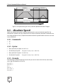

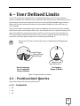
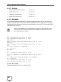


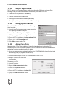
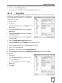

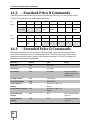
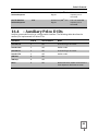

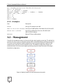
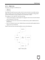


![PNQ200 Manual [02].indd](http://vs1.manualzilla.com/store/data/006077386_1-b6806c546712e4d2461330831d5b6ff4-150x150.png)