1
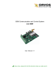
Save a tree...please don't print this document unless you really need to GSM Alarm and Control system Gsm Eco v.1.0 [email protected] / www.orvos.ee Content 1. General information 1.1. Function 1.2. Operation Description 1.3. Technical Specifications 1.4. Connector and LED Indicators Functionality 1.5. Connection Circuit 1.6. System Installation 2. System control commands 2.1. Change the way system informs about events 2.2. Enabling/disabling zones 2.3. Managing Output Controller 3. Appendix 3.1. Technical support 2 5 5 5 6 6 7 8 9 9 9 9 10 10 [email protected] / www.orvos.ee User Manual v1.0 Safety instructions Please read and follow these safety guidelines in order to maintain safety of operators and people around: • Gsm Eco (later referenced as system) contains a radio transceiver operating in 850/900/1800/1900 MHz bands • Don’t use the system in hazardous environment • Don’t use the system where it can interfere with other devices and cause any potential danger • Don’t use the system with medical devices • Don’t use the system in hazardous environment • Don’t expose the system to high humidity, chemical environment or mechanical impacts • Don’t attempt to personally repair the system Any system repairs must be done only by qualified, safety aware personnel The system must be powered by external DC 15VA power supply which must be approved by LSTEN 60950-1 standard. Any additional device connected to the Gsm Eco system must be powered up by a LST-EN 60950-1 approved supply. External power supply can be connected to AC mains only inside installation room with automatic 2-pole circuit breaker capable of disconnecting circuit in the event of short circuit or over-current condition. Open circuit breaker must have a gap between connections of more than 3mm. Mains power must be disconnected before any installation or tuning work starts. The system installation or maintenance must not be done during stormy conditions. Fuse F1 type - C1S 2.5A. Blown fuse cannot be replaced by the user and the replacement fuses have to be exactly the same as indicated by the manufacturer. The WEEE (Waste Electrical and Electronic Equipment) marking on this product or its documentation indicates that in the EU the product must not be disposed of together with household waste. 3 [email protected] / www.orvos.ee Limited Liability The buyer must agree that the system will reduce the risk of fire, theft, burglary or other dangers but does not guarantee against such events. “Orvos Monitooring LTD” will not take any responsibility regarding personal, property or revenue loss while using the system. “ Orvos Monitooring LTD” responsibility according to local laws does not exceed value of the purchased system. “ Orvos Monitooring LTD” is not affiliated with GSM operators providing cellular services therefore is not responsible for the quality of cellular services. Warranty Warranty period is a 24-month. Warranty period starts from the day the system has been purchased by the end user. The warranty is valid only if the system has been used as intended, following all guidelines listed in the manual and within specified operating conditions. Receipt with purchase date must be kept as a proof. The warranty is voided if the system has been exposed to mechanical impacts, chemicals, high humidity, fluids, corrosive and hazardous environment or other force majeure factors. Package content: 1. Gsm Eco .......................................qty. 1 About User Manual. This document describes Gsm Eco, its operation and installation. It is very important to read User Manual before start using the system. 4 [email protected] / www.orvos.ee 1. General Information 1.1 Function Gsm Eco is a microcontroller based device used to inform users about the alarm in automatic or security systems and control one electric appliance – open collector. 1.2 Operation Description Alarm and control system Gsm Eco works over GSM network. It works 24/7, i. e. it always reacts to the incoming signal. The system has two digital inputs (normal open). When the alarm siren, motion sensor, fire alarm sensor, door sensor, any other sensor or PGM output gets activated, Gsm Eco system sends an SMS messages or calls to both User1 and User2 numbers. User1 and User2 numbers must be entered into SIM card memory. Only one user can be used as well. Any number format can be used, for example +37211111111, 11111111 or even short numbers like 111. Users can choose which way the system informs about triggered zones. By default, SMS mode is enabled and SMS message with the name of the triggered input (zone) is being sent to both users (for example – ' Triggered ZONE1 ' or 'Triggered ZONE2'). When triggered zone is restored, the system sends SMS about restored zone and turns back to the previous status (for example – ' Restored ZONE1 ' or 'Restored ZONE2'). If system calling mode is enabled, at first the system will call to User1 and then to User2. If user answers to the system call, it will last for 10 seconds and then system will hang up. Gsm Eco can control 1 electronic appliance (an open collector) from a GSM phone of any of the users. For example, users can turn on or off the heating, lighting, lift the gates, blinds etc. The system remembers the status of output in case of temporary electricity failures. The system will ignore requests and calls coming from unknown telephone numbers. If user calls to the Gsm Eco, it will answer the call. This function is useful to check if the system is working correctly. 5 [email protected] / www.orvos.ee 1.3 Technical Specifications Electrical and mechanical specifications Supply voltage 9-15V 300mA DC max Current used in standby mode 30mA max GSM modem frequency 850/900/1800/1900 Mhz Number of digital inputs (normal open) 2 Allowable digital input voltage values 0-30V Impulse duration >600ms Number of outputs 1 Output max parameters Current - 500mA, voltage - 30V Output circuit Open collector output. Output is pulled to COM when enabled. Dimensions 108x52x30mm Operating temperature range -20…+55oC 1.4 Connector Functionality Picture 1 Short explanation of the main units GSM MODEM GSM network 850/900/1800/1900 MHz modem SIM CARD SIM card LED Light-emitting diodes indicator ANT GSM antenna 6 [email protected] / www.orvos.ee Connector functionality Labeling Explanation DC+ DC+ power in connector COM Earth pin OUT Controlled output (Open collector) Z1 Digital input Z1 Z2 Digital input Z2 1.5 Connection Circuit Useful Information When choosing GSM cellular provider, it is worth inquiring whether the service is used in security application assuring fast and reliable SMS message delivery and phone call connection. System Gsm Eco and security unit COM must be connected. Inputs Z1 and Z2 are connected to security unit PGM outputs if PGM are implemented as open collector circuit or any other circuit and if it commutates with COM. It is also possible to connect Z1 and Z2 inputs to, for instance, motion sensor or any other sensor as well as automatics device provided the inputs are commutated with COM. Picture 2 7 [email protected] / www.orvos.ee DC power supply connection circuit Picture 3 1.6 System installation The system box should be fixed with four screws to the wall. Since the Gsm Eco has integrated GSM antenna, it should not be installed into the metal box. For the connection of power supply, output and inputs connectors should be used 1 thread 0,5mm2 cable. Cables should be connected to the connectors and brought through the special cover hole for cables. 1. Place SIM card in the holder but make sure that SIM card PIN code request is disabled (PIN code can be disabled by putting SIM card into mobile phone and following proper menus). SIM card should not have any remaining SMS messages. 2. Connect the circuit as shown in Picture 2. Power supply cables are connected last. When connecting Gsm Eco to security central system power supply, usually the security system AUX output is used. 3. When DC power supply (ground transformer) is used connect according to Picture 3 there is no need to connect any other power supplies. 4. The system will start in less than a minute. To increase system reliability, it is recommended not to use prepaid SIM cards. The system would fail to send any messages upon depletion of prepaid account. Also it is recommended to disable call forwarding and voice mail. It is worth to choose the same GSM cellular provider as most users use assuring fast and reliable SMS message delivery and phone call connection. Even though alarm system Gsm Eco installation is not complicated, it is recommended to be performed by a person with basic knowledge in electrical engineering and electronics to avoid any system damage. 8 [email protected] / www.orvos.ee 2. System control commands !!!Very important!!! Underscore symbol ‘_’ in this manual is used to represent space. When writing SMS messages, every underscore symbol should be replaced by single space symbol. Don’t leave any space at the beginning and the end of the message. 2.1 Change the way system informs about events By default the system is set to inform users about events via SMS message. To set system to inform users via calls, user have to send SMS message to Gsm Eco: CALL To change back the system to inform users via SMS, user have to send SMS message to Gsm Eco: SMS 2.2 Enabling/disabling zones Enabling Zone Any zone can be enabled by sending the following SMS message: ZONE1:ON or ZONE2:ON Disabling Zone Any zone can be disabled by sending the following SMS message: ZONE1:OFF or ZONE2:OFF The zones can be enabled/disabled together or separately one by one. Both zones can be disabled by sending the following SMS message: ZONE1:OFF_ZONE2:OFF 2.3 Managing Output Controller Alarm system Gsm Eco has open-collector controlled output. It can be used to control various electrical devices such as electric pumps, heating, lighting, etc. When outputs are enabled, it corresponds to output pins being pulled to ground (GND). Enabling output: OUT:ON Disabling output: OUT:OFF 9 [email protected] / www.orvos.ee 3 Appendix 3.1 Technical Support Indication Possible reason Indicator is off or not blinking · no external power supply · circuit not properly connected · blown fuse · no network signal Indicator blinking several times per second · SIM card is not inserted · PIN code hasn’t been disabled · SIM card is not active System does not send any SMS messages and/or · SIM card account depleted does not ring · incorrect SIM central number · no network signal · user number is not programmed If your problem could not be fixed by the self-guide above, please contact your distributor or tech support by email [email protected] More up to date information about your device and other products can be found at the website www.orvos.ee 10