1
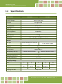
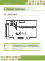
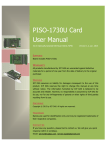
PISO-813 Series Card User Manual 32-channel Single-Ended Isolated A/D board Version 1.5, Feb. 2014 SUPPORTS Board includes PISO-813 and PISO-813U. WARRANTY All products manufactured by ICP DAS are warranted against defective materials for a period of one year from the date of delivery to the original purchaser. WARNING ICP DAS assumes no liability for damages consequent to the use of this product. ICP DAS reserves the right to change this manual at any time without notice. The information furnished by ICP DAS is believed to be accurate and reliable. However, no responsibility is assumed by ICP DAS for its use, nor for any infringements of patents or other rights of third parties resulting from its use. COPYRIGHT Copyright © 2014 by ICP DAS. All rights are reserved. TRADEMARK Names are used for identification only and may be registered trademarks of their respective companies. CONTACT US If you have any question, please feel to contact us at: [email protected]; [email protected] We will give you quick response within 2 workdays. PISO-813 Series Card 32-channel Single-Ended Isolated A/D Board TABLE OF CONTENTS 1. INTRODUCTION ................................................................................................................................................. 3 1.1 PACKING LIST........................................................................................................................................................ 4 1.2 FEATURES ............................................................................................................................................................ 4 1.3 SPECIFICATIONS .................................................................................................................................................... 5 2. HARDWARE CONFIGURATION ............................................................................................................................ 6 2.1 BOARD L AYOUT .................................................................................................................................................... 6 2.2 CARD ID SWITCH .................................................................................................................................................. 8 2.3 A/D CONVERTER OPERATION .................................................................................................................................. 9 2.3.1 A/D Conversion Block Diagram ................................................................................................................... 9 2.3.2 JP1: Analog Input Range Selection .............................................................................................................. 9 2.3.3 JP2: Analog Input Polarity Selection .......................................................................................................... 10 2.3.4 Setting Reference ........................................................................................................................................ 10 2.3.5 A/D Operation Flow..................................................................................................................................... 11 2.4 PIN ASSIGNMENTS............................................................................................................................................... 12 3. HARDWARE INSTALLATION ...............................................................................................................................13 4. SOFTWARE INSTALLATION ................................................................................................................................17 4.1 OBTAINING/INSTALLING THE DRIVER INSTALLER PACKAGE ............................................................................................ 17 4.2 PNP DRIVER INSTALLATION ................................................................................................................................... 18 4.3 VERIFYING THE INSTALLATION ................................................................................................................................ 19 4.3.1 How do I get into Windows Device Manager? .............................................................................................. 19 4.3.2 Check that the Installation ............................................................................................................................ 21 5. TESTING PISO-813 SERIES CARD ........................................................................................................................22 5.1 SELF-TEST WIRING .............................................................................................................................................. 22 5.2 EXECUTE THE TEST PROGRAM ................................................................................................................................ 23 6. I/O CONTROL REGISTER ....................................................................................................................................25 6.1 HOW TO FIND THE I/O ADDRESS ............................................................................................................................ 25 6.1.1 PIO_DriverInit ................................................................................................................................................ 26 6.1.2 PIO_GetConfigAddressSpace ......................................................................................................................... 28 6.1.3 Show_PIO_PISO ............................................................................................................................................. 29 User Manual, Ver. 1.5, Feb. 2014, PMH-003-15, Page: 1 PISO-813 Series Card 32-channel Single-Ended Isolated A/D Board 6.2 THE ASSIGNMENT OF I/O ADDRESS ........................................................................................................................ 30 6.3 THE I/O ADDRESS MAP ....................................................................................................................................... 32 6.3.1 RESET\ Control Register............................................................................................................................... 32 6.3.2 A/D Data Register .......................................................................................................................................... 33 6.3.3 Multiplexer Channel Select Register .............................................................................................................. 34 6.3.4 PGA Gain Code Register................................................................................................................................. 34 6.3.5 A/D Trigger Control Register.......................................................................................................................... 35 6.3.6 Card ID Register ............................................................................................................................................. 35 7. DEMO PROGRAMS............................................................................................................................................36 7.1 DEMO PROGRAM FOR WINDOWS .......................................................................................................................... 36 7.2 DEMO PROGRAM FOR DOS .................................................................................................................................. 38 7.3 PIO_PISO UTILITY ............................................................................................................................................. 39 APPENDIX: DAUGHTER BOARD ....................................................................................................................................41 A1. DB-37 and DN-37................................................................................................................................................. 41 A2. DB-8325............................................................................................................................................................... 41 User Manual, Ver. 1.5, Feb. 2014, PMH-003-15, Page: 2 PISO-813 Series Card 32-channel Single-Ended Isolated A/D Board 1. Introduction The PISO-813U card is the new generation product that ICP DAS provides to meet RoHS compliance requirement. The new PISO-813U card is designed as a drop-in replacement for the PISO-813, and users can replace the PISO-813 by the PISO-813U directly without software/driver modification. The PISO-813 series card is bus-typed isolated A/D board for IBM or compatible PC. The PISO-813U universal PCI card supports 3.3 V/5 V PCI bus while the PISO-813 supports 5 V PCI bus. They feature 12-bit 32 single-ended analog inputs, 3750 Vrms bus-typed isolation protection and 10 kS/s data acquisition under DOS and Windows. It is the most cost effective isolated A/D board for the universal PCI/PCI Bus in the world. The PISO-813U also adds a Card ID switch on-board. Users can set Card ID and then recognize the board by the ID via software when using two or more PISO-813U cards in one computer. These cards support various OS such as Linux, DOS, Windows 98, Windows NT, Windows 2000, 32-/64-bit Windows XP/2003/2008/Vista/7 and Windows 8. It also provides the DLL and Active X control, and various language sample programs in Turbo C++, Borland c++, Microsoft C++, Visual C++, Borland Delphi, Borland C++ Builder, Visual Basic, C#.NET, Visual Basic.NET and LabVIEW to help users to quickly and easily develop their applications. User Manual, Ver. 1.5, Feb. 2014, PMH-003-15, Page: 3 PISO-813 Series Card 32-channel Single-Ended Isolated A/D Board 1.1 Packing List The shipping package includes the following items: One PISO-813 series card hardware One printed Quick Start Guide One software utility CD Quick Start Note: If any of these items is missing or damaged, contact the dealer from whom you purchased the product. Save the shipping materials and carton in case you want to ship or store the product in the future. 1.2 Features Support the +5V PCI bus for PISO-813 Support the +3.3/+5 V PCI bus for PISO-813U 12-bit 10 kS/s A/D converter 32 single-ended analog input channels 3750 Vrms bus-type isolation protection Built-in DC/DC converter with 3000 VDC protection Analog input range: Bipolar: ±10 V, ±5 V, ±2.5 V, ±1.25 V, ±0.625 V Unipolar: 0~10 V, 0~5 V, 0~2.5 V, 0~1.25 V, 0~0.625 V Supports Card ID (SMD Switch) for PISO-813U Programmable gain control: 1, 2, 4, 8, 16 A/D trigger mode: Software Trigger A/D data transfer mode: polling SMD, Sort card User Manual, Ver. 1.5, Feb. 2014, PMH-003-15, Page: 4 PISO-813 Series Card 32-channel Single-Ended Isolated A/D Board 1.3 Specifications Model Name PISO-813U PISO-813 Analog Input Isolation Voltage 3750 Vrms (Bus Type) Channels 32 single-ended A/D Converter 12-bit, 8 μs Conversion time Sampling Rate 10 kS/s. max. FIFO Size N/A Over voltage Protection Continuous +/-35 Vp-p Input Impedance 10 MΩ/6 pF Trigger Modes Software Data Transfer Polling Accuracy 0.01 % of FSR ±1 LSB @ 25 °C, ± 10 V Zero Drift +/- 25 ppm/°C of FSR General Bus Type 3.3 V/5 V Universal PCI, 32-bit, 33 5 V PCI, 32-bit, 33 MHz MHz Data Bus 8-bit Card ID Yes(4-bit) No I/O Connector Dimensions (L x W x D) Female DB37 x 1 128 mm x 92 mm x 22mm Power Consumption 180 mm x 105 mm x 22 mm 850 mA @ +5 V Operating Temperature 0 ~ 60 °C Storage Temperature -20 ~ 70 °C Humidity 5 ~ 85% RH, non-condensing Analog Input Range Gain 1 2 4 8 16 Bipolar ±10 V ±5 V ±5 V ±2.5 V ±2.5 V ±1.25 V ±1.25 V ±0.625 V ±0.625 V Unipolar 0~10 V 0~5 V 0~2.5 V 0~1.25 V 0~0.625 V Sampling Rate Max. 10 kS/s. max. User Manual, Ver. 1.5, Feb. 2014, PMH-003-15, Page: 5 PISO-813 Series Card 32-channel Single-Ended Isolated A/D Board 2. Hardware Configuration 2.1 Board Layout Board Layout of the PISO-813. 10V Unipolar VR3 VR2 VR1 VR4 PISO-813 JP2 20V Bipolar JP1 3000Vdc photo-isolation JP3 2 8 1 7 PCI controller CON1 PCI BUS CON1 32-channel analog input, refer to Sec.2.4 for more detailed information. JP1 JP2 JP3 VR1~VR4 Input range setting, refer to Sec. 2.3.1 for more detailed information. Unipolar/Bipolar setting, refer to Sec. 2.3.2 for more detailed information. Reserved For manufacture calibration User Manual, Ver. 1.5, Feb. 2014, PMH-003-15, Page: 6 PISO-813 Series Card 32-channel Single-Ended Isolated A/D Board Board Layout of the PISO-813U. VR1 10V Unipolar VR2 VR3 VR4 PISO-813U JP2 20V Bipolar JP1 3000Vdc photo-isolation SW1 PCI controller CON1 Universal PCI BUS CON1 32-channel analog input Sec.2.4 for more detailed information. JP1 JP2 SW1 VR1~VR4 Input range setting, refer to Sec. 2.3.1 for more detailed information. Unipolar/Bipolar setting, refer to Sec. 2.3.2 for more detailed information. Card ID function, refer to Sec. 2.2 for more detailed information. For manufacture calibration User Manual, Ver. 1.5, Feb. 2014, PMH-003-15, Page: 7 PISO-813 Series Card 32-channel Single-Ended Isolated A/D Board 2.2 Card ID Switch The PISO-813U has a Card ID switch (SW1) with which users can recognize the board by the ID via software when using two or more PISO-813U cards in one computer. The default Card ID is 0x0. For detail SW1 Card ID settings, please refer to Table 2.1. Note that the Card ID function is only supported by the PISO-813U. NO ID 2 ID 3 ID 1 ID 0 SW1 1 2 3 4 (Default Settings) (*) Default Settings; OFF 1; ON 0 1 2 Card ID (Hex) ID0 ID1 Table 2.1 3 ID2 4 ID3 (*) 0x0 ON ON ON ON 0x1 OFF ON ON ON 0x2 ON OFF ON ON 0x3 OFF OFF ON ON 0x4 ON ON OFF ON 0x5 OFF ON OFF ON 0x6 ON OFF OFF ON 0x7 OFF OFF OFF ON 0x8 ON ON ON OFF 0x9 OFF ON ON OFF 0xA ON OFF ON OFF 0xB OFF OFF ON OFF 0xC ON ON OFF OFF 0xD OFF ON OFF OFF 0xE ON OFF OFF OFF 0xF OFF OFF OFF OFF User Manual, Ver. 1.5, Feb. 2014, PMH-003-15, Page: 8 PISO-813 Series Card 32-channel Single-Ended Isolated A/D Board 2.3 A/D Converter Operation 2.3.1 A/D Conversion Block Diagram Analog Input Programmable Gain Amplifier AI0 AI1 32-Channel Analog Multiplexer PGA Input Range Select Polarity Select JP1 JP2 G2~G0 AI31 D4~D0 A/D Converter Trigger Gain Code Status&D11~D0 Channel select Photocouple isolation Control Logic 2.3.2 JP1: Analog Input Range Selection 10V JP1 10V JP1 20V Input Range = 20 V 20V Input Range = 10 V (Default Settings) User Manual, Ver. 1.5, Feb. 2014, PMH-003-15, Page: 9 PISO-813 Series Card 32-channel Single-Ended Isolated A/D Board 2.3.3 JP2: Analog Input Polarity Selection UNI UNI JP2 BI BI Bipolar Mode (Default Settings) Unipolar Mode 2.3.4 Setting Reference Analog Input JP2 Polarity Select JP1 Range Select Gain -10 V ~ +10 V Bipolar 20 V 1 -5 V ~ + 5 V Bipolar 20 V 2 10 V 1 -2.5 V ~ +2.5 V Bipolar 20 V 4 10 V 2 -1.25 V ~ +1.25 V Bipolar 20 V 8 10 V 4 -0.625 V~ +0.625 V Bipolar 20 V 16 10 V 8 0 ~10 V Unipolar 10 V 1 0~5V Unipolar 10 V 2 0 ~ 2.5 V Unipolar 10 V 4 0 ~ 1.25 V Unipolar 10 V 8 0 ~ 0.625 V Unipolar 10 V 16 Note: Refer to Sec.6.3.4 for more information about gain setting. User Manual, Ver. 1.5, Feb. 2014, PMH-003-15, Page: 10 PISO-813 Series Card 32-channel Single-Ended Isolated A/D Board 2.3.5 A/D Operation Flow Step 1: Find address-mapping of PISO-813(U). (Refer to Sec.6.1) Step 2: Enable operation of PISO-813(U). (Refer to Sec.6.3.1) Step 3: Make sure the range and polarity of the analog input signal. Select suitable Setting as show in Sec.2.3.4. Step 4: Select input channel. (Refer to Sec.6.3.3) Step 5: delay 10 s. (for photocouple propagation delay and analog multiplexer settling time) Step 6: Trigger A/D converter. (Refer to Sec.6.3.5) Step 7: Delay 70 s. (for photocouple propagation delay and A/D conversion time) Step 8: Read high byte of A/D conversion data. Check the status of A/D converter until conversion ready. (Refer to Sec.6.3.2) Step 9: Read low byte of A/D conversion data. (Refer to Sec.6.3.2) Step10: A/D conversion complete. Refer to the DEMO1.C of DOS Demo. User Manual, Ver. 1.5, Feb. 2014, PMH-003-15, Page: 11 PISO-813 Series Card 32-channel Single-Ended Isolated A/D Board 2.4 Pin Assignments The Pin assignments of CON1 for 37-pin D-type female connector on the PISO-813 and PISO-813U are represented in the figure below. User Manual, Ver. 1.5, Feb. 2014, PMH-003-15, Page: 12 PISO-813 Series Card 32-channel Single-Ended Isolated A/D Board 3. Hardware Installation Note: It’s recommended to install driver first, since some operating system (such as Windows 2000) may ask you to restart the computer again after driver installation. This reduces the times to restart the computer. To install the PISO-813 series card, follow the procedure described below: Step 1: Installing PISO-813 series card driver on your computer first. For detailed information about the driver installation, please refer to Chapter 4 Software Installation. Step 2: Configuring Card ID by the SW1 DIP-Switch for PISO-813U only. For detailed information about the card ID (SW1), please refer to Sec. 2.2 Car ID Switch . User Manual, Ver. 1.5, Feb. 2014, PMH-003-15, Page: 13 PISO-813 Series Card 32-channel Single-Ended Isolated A/D Board Step 3: Shut down and power off your computer. Step 4: Remove all covers from the computer. Step 5: Select an empty PCI slot. User Manual, Ver. 1.5, Feb. 2014, PMH-003-15, Page: 14 PISO-813 Series Card 32-channel Single-Ended Isolated A/D Board Step 6: Remove the PCI slot cover form the PC. Step 7: Remove the connector cover form the PISO-813 series card. Step 8: Carefully insert your PISO-813 series card into the PCI slot. User Manual, Ver. 1.5, Feb. 2014, PMH-003-15, Page: 15 PISO-813 Series Card 32-channel Single-Ended Isolated A/D Board Step 9: Tighten the screw. Confirm the PISO-813 series card is mounted on the motherboard. Step 10: Replace the computer cover. Step 11: Power on the computer. Follow the prompt message to finish the Plug&Play steps, please refer to Chapter 4 Software Installation. User Manual, Ver. 1.5, Feb. 2014, PMH-003-15, Page: 16 PISO-813 Series Card 32-channel Single-Ended Isolated A/D Board 4. Software Installation This chapter provides a detailed description of the process for installing the PISO-813 series driver and how to verify whether the PISO-813 was properly installed. PISO-813 series card can be used on DOS, Linux and Windows 98/ME/2000 and 32-/64-bit XP/2003/Vista/7/8 based systems, and the drivers are fully Plug and Play (PnP) compliant for easy installation. 4.1 Obtaining/Installing the Driver Installer Package The driver installer package for the PISO-813 series card can be found on the supplied CD-ROM, or can be obtained from the ICP DAS FTP web site. Install the appropriate driver for your operating system. The location and addresses are indicated in the Table4-1 and Table 4-2 below. Table 4-1: UniDAQ Driver/SDK OS Windows 2000、32/64-bit Windows XP、32/64-bit Windows 2003、 32/64-bit Windows Vista、32/64-bit Windows 7、32/64-bit Windows 2008、 32/64-bit Windows 8 CD-ROM CD:\\ NAPDOS\PCI\UniDAQ\DLL\Driver\ Web Site http://ftp.icpdas.com/pub/cd/iocard/pci/napdos/pci/unidaq/dll/driver/ Driver Name UniDAQ Driver/SDK (unidaq_win_setup_xxxx.exe) Installing Procedure For detailed information about the UniDAQ driver installation, please refer to UniDAQ DLL Software Manual. The user manual is contained in: CD:\NAPDOS\PCI\UniDAQ\Manual\ http://ftp.icpdas.com/pub/cd/iocard/pci/napdos/pci/unidaq/manual/ User Manual, Ver. 1.5, Feb. 2014, PMH-003-15, Page: 17 PISO-813 Series Card 32-channel Single-Ended Isolated A/D Board Table 4-2: PISO-813 Series Classic Driver OS Windows 95/98/ME、Windows NT、Windows 2000、32-bit Windows XP、 32-bit Windows 2003、 32-bit Windows Vista、32-bit Windows 7 CD-ROM CD:\\ NAPDOS\PCI\PISO-813\DLL_OCX\ Web Site http://ftp.icpdas.com/pub/cd/iocard/pci/napdos/pci/piso-813/dll_ocx/ Driver Name PISO-813 Series Classic Driver Win2K_XP_7 Folder piso_813_win2K_xxx.exe For Windows 2000, 32-bit Windows XP/2003/Vista/7 Win98 Folder piso_813_win98_xxx.exe For Windows 95/98/ME WinNT Folder Piso_813_winnt_xxx.exe For Windows NT 4.0 For detailed information about the PISO-813 series classic driver installation, please refer to PISO-813 series classic DLL Software Manual. Installing Procedure The user manual is contained in: CD:\NAPDOS\PCI\PISO-813\Manual\ http://ftp.icpdas.com/pub/cd/iocard/pci/napdos/pci/piso-813/manual/ 4.2 PnP Driver Installation Power off the computer and install the PISO-813 series cards. Turn on the computer and Windows 95/98/ME/NT/2000 and 32-/64-bit Windows XP/2003/Vista/7/8 should automatically defect the new PCI device(s) and then ask for the location of the driver files for the hardware. If a problem is encountered during installation, refer to the PnPinstall.pdf file for more information. User Manual, Ver. 1.5, Feb. 2014, PMH-003-15, Page: 18 PISO-813 Series Card 32-channel Single-Ended Isolated A/D Board 4.3 Verifying the Installation Please open the Device Manager to verify the installation. Below are the steps for entering the Device Manager in each of the major versions of windows. Refer to appropriate for your OS, continue to complete the following steps: 4.3.1 How do I get into Windows Device Manager? Microsoft Windows 95/98/ME users Step 1: On the desktop right-click on “My Computer” and click “Properties” or open the “Control Panel” and double-click the “System” icon. Step 2: Click the “Device Manager” tab. Microsoft Windows 2000/XP users Step 1: Select “Start Settings Control Panel” and double-click the “System” icon. Step 2: Click the “Hardware” tab and then click the “Device Manager” button. Microsoft Windows 2003 users Step 1: Open the “Administrative Tools” in Control Panel. Step 2: Within the Administrative Tools click “Computer Management”. User Manual, Ver. 1.5, Feb. 2014, PMH-003-15, Page: 19 PISO-813 Series Card 32-channel Single-Ended Isolated A/D Board Microsoft Windows Vista/7 users Step 1: Click on the “Start” button. Step 2: In the Start Search box type device manager and then press enters. Microsoft Windows 8 users Step 1: To show the Start screen icon from the desktop view, simply hover your cursor over the bottom-left corner of your screen. (Or using keyboard shortcuts, click [Windows Key] +[ X] to open the Start Menu.) Step 2: Right-click on the Start screen icon then click on “Device Manager”. Right-click User Manual, Ver. 1.5, Feb. 2014, PMH-003-15, Page: 20 PISO-813 Series Card 32-channel Single-Ended Isolated A/D Board 4.3.2 Check that the Installation Check the PISO-813 series card which listed correctly or not, as illustrated below. Installation successful User Manual, Ver. 1.5, Feb. 2014, PMH-003-15, Page: 21 PISO-813 Series Card 32-channel Single-Ended Isolated A/D Board 5. Testing PISO-813 Series Card This chapter can give you the detail steps about self-test. In this way, user can confirm that PISO-813 series card well or not. Before the self-test, you must complete the hardware and driver installation. For detailed information about the hardware and driver installation, please refer to Chapter 3 Hardware Installation and Chapter 4 Software Installation. 5.1 Self-Test Wiring Prepare for device: DN-37 (optional) wiring terminal board. Provide a stable signal source. (For example, dry battery) Step 1: Use the DN-37 to connect the CON1 on the PISO-813 series card. Step 2: Wire the signal source to channel0, and then keep set the JP1 and JP2 jumper to default (refer to Sec. 2.3.1 and Sec. 2.3.2 for more detailed), and wire the signals as follows: User Manual, Ver. 1.5, Feb. 2014, PMH-003-15, Page: 22 PISO-813 Series Card 32-channel Single-Ended Isolated A/D Board 5.2 Execute the Test Program The following example use UniDAQ driver to perform self-test. If you install the PISO-813 series classic driver, please refer to Quick Start Guide of the PISO-813 (http://ftp.icpdas.com/pub/cd/iocard/pci/napdos/pci/piso-813/manual/quickstart/classic/piso-813_ quickstart_eng.pdf ) to execute the self-test. Step 1: Execute the UniDAQ Utility Program. The UniDAQ Utility.exe will be placed in the default path (C:\ICPDAS\UniDAQ\Driver\) after completing installation. 1. Double click the “UniDAQUtility.exe” 2. Confirm the PISO-813 series card had successfully installed to PC. It starts form 0. 3. Click the “TEST” button to start test. 1 2 3 User Manual, Ver. 1.5, Feb. 2014, PMH-003-15, Page: 23 PISO-813 Series Card 32-channel Single-Ended Isolated A/D Board Step 2: Get A/D function test result. 1. Click the “Analog Input” 1 Item. 2. Confirm the hardware setting (Depend on JP1 and JP2) 3. Click the “Start” button to start test. 3 2 4. Check analog input on Channel 0 testbox. The other Channels value for floating number. 4 User Manual, Ver. 1.5, Feb. 2014, PMH-003-15, Page: 24 PISO-813 Series Card 32-channel Single-Ended Isolated A/D Board 6. I/O Control Register 6.1 How to Find the I/O Address The plug&play BIOS will assign a proper I/O address to every PIO/PISO series card in the power-on stage. The fixed IDs for the PISO-813 series cards are given as follows: Table 6-1: PISO-813 (Rev 2.0 or above) PISO-813U PISO-813 (Rev 1.0) Vendor ID 0xE159 Vendor ID 0xE159 Device ID 0x02 Device ID 0x01 Sub-Vendor ID 0x80 Sub-Vendor ID Sub-Device ID 0x0A Sub-Device ID 0x02 Sub-Aux ID 0x00 Sub-Aux ID 0x00 0x0280 0x4280 We provide all necessary functions as follows: 1. PIO_DriverInit(&wBoard, wSubVendor, wSubDevice, wSubAux) 2. PIO_GetConfigAddressSpace(wBoardNo,*wBase,*wIrq, *wSubVendor, *wSubDevice, *wSubAux, *wSlotBus, *wSlotDevice) 3. Show_PIO_PISO(wSubVendor, wSubDevice, wSubAux) All functions are defined in PIO.H. Refer to Chapter 7 for more information. The important driver information is given as follows: 1. Resource-allocated information: wBase: BASE address mapping in this PC wIrq: IRQ channel number allocated in this PC 2. PIO/PISO identification information: wSubVendor: subVendor ID of this board wSubDevice: subDevice ID of this board wSubAux: subAux ID of this board User Manual, Ver. 1.5, Feb. 2014, PMH-003-15, Page: 25 PISO-813 Series Card 32-channel Single-Ended Isolated A/D Board 3. PC’s physical slot information: wSlotBus: hardware slot ID1 in this PC’s slot position wSlotDevice: hardware slot ID2 in this PC’s slot position The PIO_PISO.EXE utility will detect and show all PIO/PISO cards installed in this PC. Refer to Sec. 7.3 for more information. 6.1.1 PIO_DriverInit PIO_DriverInit(&wBoards, wSubVendor, wSubDevice, wSubAux) Parameter Description wBoards=0 to N number of boards found in this PC wSubVendor subVendor ID of board to find wSubDevice subDevice ID of board to find wSubAux subAux ID of board to find This function can detect all PIO/PISO series card in the system. It is implemented based on the PCI plug&play mechanism-1. It will find all PIO/PISO series cards installed in this system and save all their resource in the library. Sample program 1: Find all PISO-813 in this PC wSubVendor=0x80; wSubDevice=0xa; wSubAux=0x00; /* for PISO-813 */ wRetVal=PIO_DriverInit(&wBoards, wSubVendor,wSubDevice,wSubAux); printf("Threr are %d PISO-813 Cards in this PC\n",wBoards); /* step2: save resource of all PISO-813 cards installed in this PC */ for (i=0; i<wBoards; i++) { PIO_GetConfigAddressSpace(i,&wBase,&wIrq,&wID1,&wID2,&wID3, &wID4,&wID5); printf("\nCard_%d: wBase=%x, wIrq=%x", i,wBase,wIrq); wConfigSpace[i][0]=wBaseAddress; /*save all resource of this card */ wConfigSpace[i][1]=wIrq; /* save all resource of this card */ } User Manual, Ver. 1.5, Feb. 2014, PMH-003-15, Page: 26 PISO-813 Series Card 32-channel Single-Ended Isolated A/D Board Sample program 2: Find all PIO/PISO in this PC (refer to Sec. 7.3 for more information) wRetVal=PIO_DriverInit(&wBoards,0xff,0xff,0xff); /*find all PIO_PISO*/ printf("\nThrer are %d PIO_PISO Cards in this PC",wBoards); if (wBoards==0 ) exit(0); printf("\n-----------------------------------------------------"); for(i=0; i<wBoards; i++) { PIO_GetConfigAddressSpace(i,&wBase,&wIrq,&wSubVendor, &wSubDevice,&wSubAux,&wSlotBus,&wSlotDevice); printf("\nCard_%d:wBase=%x,wIrq=%x,subID=[%x,%x,%x], SlotID=[%x,%x]",i,wBase,wIrq,wSubVendor,wSubDevice, wSubAux,wSlotBus,wSlotDevice); printf(" --> "); ShowPioPiso(wSubVendor,wSubDevice,wSubAux); } User Manual, Ver. 1.5, Feb. 2014, PMH-003-15, Page: 27 PISO-813 Series Card 32-channel Single-Ended Isolated A/D Board 6.1.2 PIO_GetConfigAddressSpace PIO_GetConfigAddressSpace(wBoardNo,*wBase,*wIrq, *wSubVendor, *wSubDevice, *wSubAux, *wSlotBus, *wSlotDevice) Parameter Description wBoardNo=0 to N totally N+1 boards found by PIO_DriveInit(….) wBase base address of the board control word wIrq allocated IRQ channel number of this board wSubVendor subVendor ID of this board wSubDevice subDevice ID of this board wSubAux subAux ID of this board wSlotBus hardware slot ID1 of this board wSlotDevice hardware slot ID2 of this board The user can use this function to save resource of all PIO/PISO cards installed in this system. Then the application program can control all functions of PIO/PISO series card directly. The sample program source is given as follows: /* step1: detect all PISO-813 cards first */ wSubVendor=0x80; wSubDevice=0xa; wSubAux=0x0; /* for PISO-813 */ wRetVal=PIO_DriverInit(&wBoards, wSubVendor,wSubDevice,wSubAux); printf("Threr are %d PISO-813 Cards in this PC\n",wBoards); /* step2: save resource of all PISO-813 cards installed in this PC */ for (i=0; i<wBoards; i++) { PIO_GetConfigAddressSpace(i,&wBase,&wIrq,&t1,&t2,&t3,&t4,&t5); printf("\nCard_%d: wBase=%x, wIrq=%x", i,wBase,wIrq); wConfigSpace[i][0]=wBaseAddress; /* save all resource of this card */ wConfigSpace[i][1]=wIrq; /* save all resource of this card */ } /* step3: control the PISO-813 directly */ wBase=wConfigSpace[0][0]; /* get base address the card_0 */ outport(wBase,1); /* enable all D/I/O operation of card_0 */ wBase=wConfigSpace[1][0]; outport(wBase,1); /* get base address the card_1 */ /* enable all D/I/O operation of card_1*/ User Manual, Ver. 1.5, Feb. 2014, PMH-003-15, Page: 28 PISO-813 Series Card 32-channel Single-Ended Isolated A/D Board 6.1.3 Show_PIO_PISO Show_PIO_PISO(wSubVendor,wSubDevice,wSubAux) Parameter Description wSubVendor subVendor ID of board to find wSubDevice subDevice ID of board to find wSubAux subAux ID of board to find This function will show a text string for this special subIDs. This text string is the same as that defined in PIO.H The demo program is given as follows: wRetVal=PIO_DriverInit(&wBoards,0xff,0xff,0xff); /*find all PIO_PISO*/ printf("\nThrer are %d PIO_PISO Cards in this PC",wBoards); if (wBoards==0 ) exit(0); printf("\n-----------------------------------------------------"); for(i=0; i<wBoards; i++) { PIO_GetConfigAddressSpace(i,&wBase,&wIrq,&wSubVendor, &wSubDevice,&wSubAux,&wSlotBus,&wSlotDevice); printf("\nCard_%d:wBase=%x,wIrq=%x,subID=[%x,%x,%x], SlotID=[%x,%x]",i,wBase,wIrq,wSubVendor,wSubDevice, wSubAux,wSlotBus,wSlotDevice); printf(" --> "); ShowPioPiso(wSubVendor,wSubDevice,wSubAux); } User Manual, Ver. 1.5, Feb. 2014, PMH-003-15, Page: 29 PISO-813 Series Card 32-channel Single-Ended Isolated A/D Board 6.2 The Assignment of I/O Address The Plug&Play BIOS will assign the proper I/O address to a PIO/PISO series card. If there is only one PIO/PISO board, the user can identify the board as card_0. If there are two PIO/PISO boards in the system, it is very difficult to identify which board is card_0. The software driver can support a maximum of 16 boards. Therefore, the user can install 16 PIO/PSIO series cards onto one PC system. The methods used to find and identify card_0 and card_1 is demonstrated below. The simplest way to identify which card is card_0 is to use wSlotBus and wSlotDevice in the following manner: Step 1: Remove all PISO-813 series boards from the PC. Step 2: Install one PISO-813 series into the PC’s PCI_slot1, run PIO_PISO.EXE. Then record the wSlotBus1 and wSlotDevice1 information. Step 3: Remove all PISO-813 series boards from the PC. Step 4: Install one PISO-813 series into the PC’s PCI_slot2 and run PIO_PISO.EXE. Then record the wSlotBus2 and wSlotDevice2 information. Step 5: Repeat Steps(3) and (4) for every PCI_slot and record all information from wSlotBus and wSlotDevice. The records may look similar to the table follows: Table 6-2: PC’s PCI Slot WslotBus WslotDevice Slot_1 0 0x07 Slot_2 0 0x08 Slot_3 0 0x09 Slot_4 0 0x0A Slot_5 1 0x0A Slot_6 1 0x08 Slot_7 1 0x09 Slot_8 1 0x07 PCI-BRIDGE User Manual, Ver. 1.5, Feb. 2014, PMH-003-15, Page: 30 PISO-813 Series Card 32-channel Single-Ended Isolated A/D Board The above procedure will record all the wSlotBus and wSlotDevice information on a PC. These values will be mapped to this PC’s physical slot and this mapping will not be changed for any PIO/PISO cards. Therefore, this information can be used to identify the specified PIO/PISO card by following steps: Step1: Using the wSlotBus and wSlotDevice information from Table 6-2. Step2: Enter the board number into PIO_GetConfigAddressSpace(…) function to get the information for a specific card, especially the wSlotBus and wSlotDevice details. Step3: Identify the specific PIO/PISO card by comparing the data of the wSlotBus and wSlotDevice from Step1 and Step2. Note: that normally the card installed in slot 0 is card0 and the card installed in slot1 is card1 for PIO/PISO series cards. User Manual, Ver. 1.5, Feb. 2014, PMH-003-15, Page: 31 PISO-813 Series Card 32-channel Single-Ended Isolated A/D Board 6.3 The I/O Address Map The I/O address for PISO-813 series cards are automatically assigned by the main board ROM BIOS. The I/O address can also be re-assigned by the user. It is strongly recommended that users do not change the I/O address. The Plug&Play BIOS will effectively perform the assignment of proper I/O addresses to each PISO-813 series card. The I/O address for the PISO-813 and PISO-813U are given in the table below, all of which are based on the base address of each card. Table 6-3: Refer to Sec. 6.1 for more information about wBase. Address Read Write wBase+0 RESET\ Control Register RESET\ Control Register wBase+0xd0 Low byte of A/D Data - wBase+0xd4 High byte of A/D Data - wBase+0xe0 - Multiplexer channel select register wBase+0xe4 - PGA gain code register wBase+0xf0 - A/D trigger control register wBase+0xfc Read Card ID - 6.3.1 RESET\ Control Register (Read/Write): wBase+0 Bit 7 Bit 6 Bit 5 Bit 4 Bit 3 Bit 2 Bit 1 Bit 0 Reserved Reserved Reserved Reserved Reserved Reserved Reserved RESET\ When the PC’s power is first turned on, RESET\ signal is in a Low-state. This will disable all D/I/O operations. The user has to set the RESET\ signal to a High-state before any D/I/O command applications are initiated. For example: outportb (wBase,1); outportb (wBase,0); /* RESET\=High all D/I/O are enable now */ /* RESET\=Low all D/I/O are disable now */ User Manual, Ver. 1.5, Feb. 2014, PMH-003-15, Page: 32 PISO-813 Series Card 32-channel Single-Ended Isolated A/D Board 6.3.2 A/D Data Register (Read): wBase+0xd0 Low Byte of A/D Conversion Data Bit 7 Bit 6 Bit 5 Bit 4 Bit 3 Bit 2 Bit 1 Bit 0 D7 D6 D5 D4 D3 D2 D1 D0 (Read): wBase+0xd4 High Byte of A/D Conversion Data Bit 7 Bit 6 Bit 5 Bit 4 Bit 3 Bit 2 Bit 1 Bit 0 - - - Status D11 D10 D9 D8 Status: The status bit is used as an indicator for A/D conversion. It is used for software polling. Setting values are as follows: 0 A/D conversion is completed 1 A/D conversion is not completed D0 to D11: A/D Conversion Data For example: do { HighByte=inportb(wBase+0xd4); }while(HighByte&0x10); /* check status until conversion complete */ LowByte=inportb(wBase+0xd0); Data=(HighByte<<8)+LowByte; User Manual, Ver. 1.5, Feb. 2014, PMH-003-15, Page: 33 PISO-813 Series Card 32-channel Single-Ended Isolated A/D Board 6.3.3 Multiplexer Channel Select Register (Write): wBase+0xe0 Bit 7 Bit 6 Bit 5 Bit 4 Bit 3 Bit 2 Bit 1 Bit 0 - - - D4 D3 D2 D1 D0 For example: outportb(wBase+0xe0,0); outportb(wBase+0xe0,1); outportb(wBase+0xe0,31); /* Select analog input channel /* Select analog input channel /* Select analog input channel 0 */ 1 */ 31 */ 6.3.4 PGA Gain Code Register (Write): wBase+0xe4 Bit 7 Bit 6 Bit 5 Bit 4 Bit 3 Bit 2 Bit 1 Bit 0 - - - - - D2 D1 D0 For example: outportb(wBase+0xe4,0); outportb(wBase+0xe4,1); outportb(wBase+0xe4,2); outportb(wBase+0xe4,3); /* Select PGM Gain = 1 /* Select PGM Gain = 2 /* Select PGM Gain = 4 /* Select PGM Gain = 8 */ */ */ */ User Manual, Ver. 1.5, Feb. 2014, PMH-003-15, Page: 34 PISO-813 Series Card 32-channel Single-Ended Isolated A/D Board 6.3.5 A/D Trigger Control Register (Read): wBase+0xf0 Bit 7 Bit 6 Bit 5 Bit 4 Bit 3 Bit 2 Bit 1 Bit 0 - - - - - - - - The A/D data transfer mode is polling. Before read the conversion data, the A/D converter must be trigger by dummy write A/D Trigger Control Register. (Refer to Sec.2.3.5 for more information about A/D converter operation) For example: outportb(wBase+0xf0,0); /* Trigger A/D converter */ 6.3.6 Card ID Register (Read): wBase+0xfc Bit 7 Bit 6 Bit 5 Bit 4 Bit 3 Bit 2 Bit 1 Bit 0 0 0 0 0 ID3 ID2 ID1 ID0 For example: wCardID = inportb(wBase+0xfc); /* read Card ID */ Note: The Card ID function is only supported by the PISO-813U (Ver. 1.0 or above) User Manual, Ver. 1.5, Feb. 2014, PMH-003-15, Page: 35 PISO-813 Series Card 32-channel Single-Ended Isolated A/D Board 7. Demo Programs 7.1 Demo Program for Windows All demo programs will not work properly if the DLL driver has not been installed correctly. During the DLL driver installation process , the install-shields will register the correct kernel driver to the operation system and copy the DLL driver and demo programs to the correct position based on the driver software package you have selected (Win98/Me/NT/2K and 32-/64-bit winXP/2003/Vista/7/8). Once driver installation is complete, the related demo programs and development library and declaration header files for different development environments will be presented as follows. Demo Program for PISO-813 Series Classic Driver The demo program is contained in: CD:\NAPDOS\PCI\PISO-813\DLL_OCX\Demo\ http://ftp.icpdas.com/pub/cd/iocard/pci/napdos/pci/piso-813/dll_ocx/demo/ BCB4 for Borland C++ Builder 4 PISO813.H Header files PISO813.LIB Linkage library for BCB only Delphi4 for Delphi 4 PISO813.PAS Declaration files VC6 for Visual C++ 6 PISO813.H Header files PISO813.LIB Linkage library for VC only VB6 for Visual Basic 6 PISO813.BAS Declaration files VB.NET2005 for VB.NET2005 PISO813.vb Visual Basic Source files CSharp2005 for C#.NET2005 PISO813.cs Visual C# Source files For detailed information about the DLL function of the PISO-813 series card, please refer to PISO-813 DLL Software Manual (CD:\NAPDOS\PCI\PISO-813\Manual\) User Manual, Ver. 1.5, Feb. 2014, PMH-003-15, Page: 36 PISO-813 Series Card 32-channel Single-Ended Isolated A/D Board Demo Program for UniDAQ SDK Driver The demo program is contained in: CD:\NAPDOS\PCI\UniDAQ\DLL\Demo\ http://ftp.icpdas.com/pub/cd/iocard/pci/napdos/pci/unidaq/dll/demo/ BCB6 for Borland C++ Builder 6 UniDAQ.H Header files UniDAQ.LIB Linkage library for BCB only Delphi6 for Delphi 6 UniDAQ.PAS Declaration files VB6 for Visual Basic 6 UniDAQ.BAS Declaration files CSharp2005 for C#.NET2005 UniDAQ.cs Visual C# Source files VC6 for Visual C++ 6 UniDAQ.H Header files UniDAQ.LIB Linkage library for VC only VB.NET2005 for VB.NET2005 UniDAQ.vb Visual Basic Source files VC.NET2005 for VC.NET2005 (32-bit) UniDAQ.H Header files UniDAQ.LIB Linkage library for VC only VC.NET2005 for VC.NET2005 (64-bit) UniDAQ.H Header files UniDAQ.LIB Linkage library for VC only For detailed information about the DLL function and demo program of the UniDAQ, please refer to UniDAQ DLL Software Manual (CD:\NAPDOS\PCI\UniDAQ\Manual\) User Manual, Ver. 1.5, Feb. 2014, PMH-003-15, Page: 37 PISO-813 Series Card 32-channel Single-Ended Isolated A/D Board 7.2 Demo Program for DOS The demo program is contained in: CD:\NAPDOS\PCI\PISO-813\DOS\PISO813\ http://ftp.icpdas.com/pub/cd/iocard/pci/napdos/pci/piso-813/dos/piso-813/ \TC\*.* for Turbo C 2.xx or above \MSC\*.* for MSC 5.xx or above \BC\*.* for BC 3.xx or above \TC\LIB\*.* for TC Library \TC\DEMO\*.* for TC demo program \TC\DIAG\*.* for TC diagnostic program \TC\LIB\Large\*.* \TC\LIB\Huge\*.* \TC\LIB\Large\PIO.H \TC\LIB\Large\TCPIO_L.LIB \TC\LIB\Huge\PIO.H \TC\LIB\Huge\TCPIO_H.LIB TC Large Model Library TC Huge Model Library File TC Declaration File TC Large Model Library File TC Declaration File TC Huge Model Library File \MSC\LIB\Large\PIO.H \MSC\LIB\Large\MSCPIO_L.LIB \MSC\LIB\Huge\PIO.H \MSC\LIB\Huge\MSCPIO_H.LIB \BC\LIB\Large\PIO.H \BC\LIB\Large\BCPIO_L.LIB \BC\LIB\Huge\PIO.H \BC\LIB\Huge\BCPIO_H.LIB MSC Declaration File MSC Large Model Library File MSC Declaration File MSC Huge Model Library File BC Declaration File BC Large Model Library File BC Declaration File BC Huge Model Library File For detailed information about the DLL function of the DOS, please refer to PISO-813 DLL Software Manual (CD:\NAPDOS\PCI\PISO-813\Manual\) User Manual, Ver. 1.5, Feb. 2014, PMH-003-15, Page: 38 PISO-813 Series Card 32-channel Single-Ended Isolated A/D Board 7.3 PIO_PISO Utility The PIO_PISO.EXE is valid for all PIO/PISO cards. This program shows all PCI hardware ID regarding the PIO and PISO series DAQ cards. It is useful to test if the card Plug & Play successfully when the computer bootup. If the PIO or PISO series card does not shown in the screen correctly, please try to use another PCI slot and try again. The user can execute the PIO_PISO.EXE to get the following information: List all PIO/PISO cards installed in this PC List all resources allocated to every PIO/PISO cards List the wSlotBus and wSlotDevice for specified PIO/PISO card identification. (refer to Sec. 6.2 for more information about the assignment of I/O Address) For Windows OS The PIO_PISO.EXE for Windows is contained in: CD:\NAPDOS\PCI\Utility\Win32\PIO_PISO http://ftp.icpdas.com/pub/cd/iocard/pci/napdos/pci/utility/win32/pio_piso/ After executing the utility, the detail information for all PIO/PISO cards that installed in the PC will be shown as follows: User Manual, Ver. 1.5, Feb. 2014, PMH-003-15, Page: 39 PISO-813 Series Card 32-channel Single-Ended Isolated A/D Board For DOS The PIO_PISO.EXE for DOS is contained in: CD:\NAPDOS\PCI\Utility\DOS\ http://ftp.icpdas.com/pub/cd/iocard/pci/napdos/pci/utility/dos/ The PIO_PISO program source is given as follows: /* -------------------------------------------------------------- */ /* Find all PIO_PISO series cards in this PC system */ /* step 1 : plug all PIO_PISO cards into PC */ /* step 2 : run PIO_PISO.EXE */ /* ------------------------------------------------------------- */ #include "PIO.H" WORD wBase,wIrq; WORD wBase2,wIrq2; int main() { int i,j,j1,j2,j3,j4,k,jj,dd,j11,j22,j33,j44; WORD wBoards,wRetVal; WORD wSubVendor,wSubDevice,wSubAux,wSlotBus,wSlotDevice; char c; float ok,err; clrscr(); wRetVal=PIO_DriverInit(&wBoards,0xff,0xff,0xff); /*for PIO-PISO */ printf("\nThrer are %d PIO_PISO Cards in this PC",wBoards); if (wBoards==0 ) exit(0); printf("\n-----------------------------------------------------"); for(i=0; i<wBoards; i++) { PIO_GetConfigAddressSpace(i,&wBase,&wIrq,&wSubVendor, &wSubDevice,&wSubAux,&wSlotBus,&wSlotDevice); printf("\nCard_%d:wBase=%x,wIrq=%x,subID=[%x,%x,%x], SlotID=[%x,%x]",i,wBase,wIrq,wSubVendor,wSubDevice, wSubAux,wSlotBus,wSlotDevice); printf(" --> "); ShowPioPiso(wSubVendor,wSubDevice,wSubAux); } PIO_DriverClose(); } User Manual, Ver. 1.5, Feb. 2014, PMH-003-15, Page: 40 PISO-813 Series Card 32-channel Single-Ended Isolated A/D Board Appendix: Daughter Board A1. DB-37 and DN-37 DB-37: The DB-37 is a general purpose daughter board for D-sub 37 pins. It is designed for easy wire connection via pin-to-pin. Use a 37-pin cable (e.g. CA-3710, etc.) to connect DB-37 to CON1 of the PISO-813 series card. DB-37 DN-37: The DN-37 is a general purpose daughter board for DB-37 pins with DIN-Rail Mountings. They are also designed for easy wire connection via pin-to-pin. Use a 37-pin cable (e.g. CA-3710, etc.) to connect to CON1 of the PISO-813 series card by DN-37. DN-37 A2. DB-8325 The DB-8325 is a general purpose screw terminal board. It is designed for easy wire connection. The DB-8325 consists of one DB-37. Use a 37-pin cable (e.g. CA-3710, etc.) to connect DB-8325 to CON1 of the PISO-813 series card. DB-8325 User Manual, Ver. 1.5, Feb. 2014, PMH-003-15, Page: 41