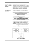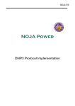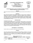
1
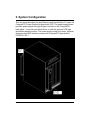
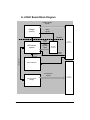
PWRS-0026
BCKP-0029
6U CompactPCI
Power Supply with UPS
13 Altalef St.
Yehud, Israel 56216
Tel: 972 (3) 632-0533
Fax: 972 (3) 632-0458
www.tenta.com
919 Kifer Road
Sunnyvale, CA 94086 USA
Tel: (408) 328-1370
Fax: (408) 328-1371
Document Revisions
Rev
Comment
BY
Date
E0
Release - Preliminary
DG
11/25/00
E0.1
Additions and corrections
DG
12/07/00
E1.0
Release, Windows utility added, UPS time
defaults changed
DG
04/16/01
E2.0
Update document format
TJ
01/10/02
PWRS-0026 User Manual
Page 2 of 19
Table of Contents
I.
Ordering Information ...................................................................... 4
II.
System Configuration ..................................................................... 5
III.
Specifications .............................................................................. 7
A.
Physical Specifications ....................................................................... 7
B.
Environmental Specifications............................................................. 8
C.
Front Panel Indicators ......................................................................... 8
D.
Power Specification............................................................................. 8
E.
On Board Fuses ................................................................................... 9
IV.
Power Supply Card.................................................................... 10
A.
Power Supply Block Diagram ........................................................... 10
B.
UPS Option......................................................................................... 11
C.
Functionality ...................................................................................... 11
V.
Logic Board ................................................................................... 12
A.
VI.
A.
LOGIC Board Block Diagram ............................................................ 13
BACKUP Board .......................................................................... 14
Battery Backup Block Diagram......................................................... 15
VII.
PCI Driver Operation ................................................................. 16
VIII.
Handshake Mode Operation ..................................................... 17
IX.
Memory Map............................................................................... 18
X.
Warranty......................................................................................... 19
PWRS-0026 User Manual
Page 3 of 19
I. Ordering Information
Part Number
AS00026-01
AS00030-01
AS00043-01
AS00029-01
PWRS-0026 User Manual
Description
Power supply card, 130 watts, 6U, M type connector
UPS logic board, 6U
Power supply with UPS logic board
Battery back up module, 6U
Page 4 of 19
II. System Configuration
This document describes the specifications and functionality of Tenta’s 6U
CompactPCI Power Distribution board with UPS. The power supply board
provides power signals through M-type connector to the CompactPCI
back plane. It may be used stand alone, or with the optional UPS logic
and battery backup module. The power supply board form factor, physical
dimension and BUS interface comply with CompactPCI Specification
PICMG 2.0 R2.1.
PWRS-0026 User Manual
Page 5 of 19
The full system consists of three main components. The power supply
can be used stand alone, or combined with items #2 - #3 for a full UPS
system.
1) PS
2) LOGIC
3) BACKUP
Power conversion :
AC/DC: 90-132 / 180-264 VAC -> 15V
DC/DC: conversion of 15V to 5V,3.3V,±12V
Charger for Ni-Cd battery
PCI Interface
Serial Logic
Ni-Cd battery pack
Serial Interface
PWRS-0026 User Manual
Page 6 of 19
III. Specifications
A. Physical Specifications
Criteria
PS and LOGIC
PCB Dimensions
Form Factor
Connectors
Front Panel
Weight
BACKUP
PCB Dimensions
Form Factor
Connectors
Front Panel
Weight
PWRS-0026 User Manual
Specifications
233MM (9.1875”) Height X 160MM
(6.2992”) Depth X 1.6MM (0.0629”)
Thickness
Plug in Euro card, 6U Height, IEEE
(1101.1, 101.10 and P1101.11)
M-Type Connector on power board;
metric 2.0mm grid female connector for
J1 (cPCI BUS) and J5 (signal
distribution) on logic board
262mm Height X 50mm Width x 2mm
Thickness, with power and status
indication LED’s
900g
233MM (9.1875”) Height X 80MM
(3.1496”) Depth X 1.6MM (0.0629”)
Thickness
Plug in Euro card, 6U Height, IEEE
(1101.1, 101.10 and P1101.11)
Metric 2.0mm grid female connector for
J5 (signal distribution)
262mm Height X 50mm Width x 2mm
Thickness with dsub9 female
(handshake signal connector)
800g
Page 7 of 19
B. Environmental Specifications
Criteria
Operating
temperature
Storage
Humidity
Specifications
0-70 ºC
-40 to +85 ºC
5 to 95% non-condensing
C. Front Panel Indicators
Label
+12V
-12V
+15V
+5V
+3.3V
NT SHT DWN
PWR FAIL
CHRG/COMP
Function
+12 VDC supply, green
-12 VDC supply, green
+15 VDC supply, green
+5 VDC supply, green
+3.3 VDC supply, green
NT in shutdown state, green, blinking
Loss of AC power, red
Battery charging, orange; Battery fully
charged, green
D. Power Specification
Criteria
Voltage
Power
AC - DC
90-132 / 180-264 -> 15V
~130W
DC - DC
15V -> 3.3V
~30W
15V -> 5V
~75W
15V -> ±12V
~25W
PWRS-0026 User Manual
Page 8 of 19
E. On Board Fuses
Fuse
F1
F2
F3
F4
F5
PWRS-0026 User Manual
Voltage
+12V
-12V
+3.3V
+5V
+5V
Value
3A
0.375A
5A
10A
10A
Page 9 of 19
IV. Power Supply Card
PS PCBA is responsible for converting AC input line to all required DC
voltages needed in a cPCI system. It uses an AC/DC of 130W for the first
phase and is designed for future upgrade to 180W with no additional PCB
modifications. Three DC/DC converters provide conversion of the 15V
(AC/DC output) to all required DC levels; one for 5V, one for 3.3V and one
for ±12V.
A. Power Supply Block Diagram
AC IN
connector
DC-DC
5V,75W
ACL
ACN
AC/DC
Input :
190-132/180-264V
Output :
15V
DC-DC
3V,30W
M-type
Conne
ctor
DC-DC
+-12V,25W
LED Indication
Transition
Connector
signals
including:
charger
status, NT
staus and
power failure
LED's
P/S board shown with Logic board
PWRS-0026 User Manual
Page 10 of 19
B. UPS Option
The UPS option provides battery backup, up to 5 minutes, in
order to allow the operating system to safely shut down upon
a power failure. This system consists of two major
components:
LOGIC is a mezzanine board to the PS card. It contains
cPCI backplane connections through J1 and J5. J1 is used
for PCI interface to the HOST, and J5 is used for power
signal transition between the battery and the charger, and
also used to route the control signal for power sequence
between HOST and UPS control when in serial handshake
mode.
BACKUP is a cPCI card which is inserted from the back
side of the cage behind the second slot and contains the
battery and serial port handshake connector.
C. Functionality
The UPS provides backup power during a power loss. The
logic is dependent upon the driver installed. A driver for
serial handshake and for a full PCI mode is available. In
either case, a charge circuit continually monitors the battery
and provides charging when needed. The charge point has
built in hysteresis. During a standard operating system
shutdown, the UPS is not activated. During power loss, a
shutdown under battery power is completed.
PWRS-0026 User Manual
Page 11 of 19
V. Logic Board
LOGIC board is responsible for :
1) PCI interface with the HOST, achieved by using a smart PCI to
LOCAL bridge
2) UPS control – including charger circuitry, power failure detection
and handshake with NT via serial bus or CPCI bus for power shut
down sequence.
3) Routing power signals from the BACKUP board to PS during power
failure.
The power failure detection circuit is responsible for identifying a power
failure and switching the Backup. During a short power loss, the logic
(with selectable FAIL_TIME), may rely on internal capacitance to ensure
continuous operation rather than aborting to a shutdown mode.
PWRS-0026 User Manual
Page 12 of 19
A. LOGIC Board Block Diagram
Battery related
signals
Charger
circuitry
Charge
Control
UPS control
system
Staus
signals
Isolation
power
fault
staus
indication
LED's
J5 PCI
Connector
Transition
connector
battery
on/off
configuration
power
sequence
Control
Serial Interface
PCI Interface
signals
PCI to LOCAL
Bridge
PWRS-0026 User Manual
J1 PCI
Connector
Page 13 of 19
VI. BACKUP Board
BACKUP holds the battery pack on rear side of the cage, and provides
power to the LOGIC board through J5 (CPCI standard connector). A Dsub 9 connector also provides handshake logic signals with a selected
COM port.
The battery pack is capable of powering a 130 watt system for a minimium
of 5 minutes. The 12 VDC battery pack consists of (10) 1.2 VDC cells in
series, and can supply 10.8 amps for more than 5 minutes as shown in
the graph below:
120 W
72 W
48 W
Charging time of fully discharged battery pack lasts 5 hours maximum.
Typical charging time is 3.6 hours. Battery is rated for 500 full discharge
to charge cycles.
PWRS-0026 User Manual
Page 14 of 19
A. Battery Backup Block Diagram
control
signals
Battery Pack
battery power
battery on/off
Switch on/
off circuit
CPCI J5
connector
battery power
NT & UPS derial interface
Serial port
Serial Handshake Signal Connector
Ref
1
2
Signal name
NT_CLSD
NT_SHTDWN_BUF
PWRS-0026 User Manual
BACKUP Signal
4
8
COM x Signal
4
8
Page 15 of 19
VII. PCI Driver Operation
A Windows NT driver is provided to manage all UPS functions. After
installation, the driver will run as a back ground service, and provides
access to all set up parameters through the Control Panel icon. Select
and fill in any parameters which need to be modified from default. All
communication between the processor and UPS is through the PCI bus.
Default for UPS Time is 120,000 ms.
Default for Fail Time is 1,000 ms.
Logic:
On power up, the UPS driver task starts automatically. Assuming that the
UPS driver is installed and activated through the Control Panel utility, the
UPS is enabled and begins charging. CHRG/COMP will be orange. Upon
being fully charged, CHRG/COMP will turn green.
The system continuously checks for a power failure, indicated by the
PWR FAIL LED. A voltage loss for less than Fail Time will have no effect
on the system. A voltage loss for Fail Time or greater will result in System
Shutdown with battery backup assistance.
All programs will be shut down, and the Registry will be saved. The UPS
will monitor this activity, and upon completion will turn off the System.
If for any reason this does not happen (ie. operating system locks up), the
UPS will turn off the System after a time period of UPS_TIME.
Upon a User selected Shutdown of NT, all battery backup functionality is
disabled.
PWRS-0026 User Manual
Page 16 of 19
VIII. Handshake Mode Operation
The following describes the internal logic and variables used in
Handshake Mode. The standard NT UPS functionality is used in addition
to the following logic. A driver and DOS utility are provided with this
functionality.
On power up, UPS_ENABLE = 0
After NT completes boot, set UPS_ENABLE = 1
POWER_OK = 1 until power detection circuit determines power loss, then
POWER_OK = 0
FAIL_MODE = 1 if POWER_OK = 0 for more than FAIL_TIME
If FAIL_MODE and UPS_ENABLE = 1, provide UPS battery power until
time > UPS_TIME or REMOTE_UPS_SHUTDOWN is received.
On standard NT shut-down, UPS functionality is disabled.
Definition of terms:
UPS_ENABLE
POWER_OK
FAIL_TIME
UPS_TIME
REMOTE_UPS_SHUTDOWN
PWRS-0026 User Manual
Internal register which controls enable
state of UPS
Internal register which indicates status of
incoming power line
Time that a no power condition is
detected until FAIL_MODE = 1
Time that power is supplied after
FAIL_MODE = 1
COM port handshake signal from CPU
to shut down supply. Default time delay
is 2 minutes.
Page 17 of 19
IX. Memory Map
Name
Description
Offset
Size
Values
Default
Updated by
UPS_ENABLE
Enable battery to supply power to the BUS in “fail mode”
0x0
32bit
1 Enable
0 Disable
Disable
NT program
Name
Description
Offset
Size
Values
Scale Factor
Default
Updated by
UPS_TIME
Time to supply power for shutdown
0x4
32bit
10000ms to 300000ms
127ms
120000ms
NT program
Name
Description
Offset
Size
Values
Scale Factor
Default
Updated by
FAIL_TIME
Acceptable duration of power loss before triggering a shutdown
0x8
32bit
50ms to 2000ms
16 ms
1000 ms
NT program
Name
Description
Offset
Size
Values
POWER_OK
Power status
0xC
32bit
0 no power
1 power OK
1
Power supply board
Default
Updated by
PWRS-0026 User Manual
Page 18 of 19
X. Warranty
Tenta Technology warrants the original purchaser for two years from the
date of delivery for any defect in the product, material or workmanship.
Product should be used in suitable installation environment and for the
purposes it was designed. Any damages caused by natural disasters such
as: fire, flood, wind and lightning are not covered. For more information,
please contact Tenta Technology customer support (see locations on
front page). Tenta Technology hardware and software are not intended
for use in any manner when human life or safety is at risk and not for use
in life support equipment.
PWRS-0026 User Manual
Page 19 of 19