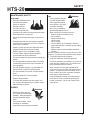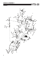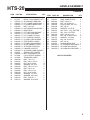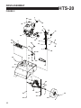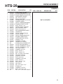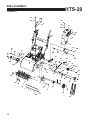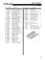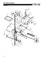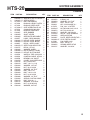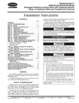
1
HYDRO OVERSEEDER
MODELS:
HTS-20H
PARTS MANUAL
Original Language Instructions
Rev A. 04-2014
MAN 4170646
Hydro Overseeder Honda GX270
OPERATOR'S MANUAL 4170647
CALIFORNIA
WARNING
Proposition 65 Warning
Diesel engine exhaust and some
of its constituents are known to the
State of California to cause cancer,
birth defects and other reproductive
harm.
The engine exhaust from this product
contains chemicals known to the State
of California to cause cancer, birth
defects or other reproductive harm.
CALIFORNIA
Proposition 65 Warning
Battery posts, terminals, wiring
insulation, and related accessories
contain lead and lead compounds,
chemicals known to the State of
California to cause cancer and birth
defects or other reproductive harm.
WASH HANDS AFTER HANDLING.
HTS-20
IMPORTANT MESSAGE
Thank you for purchasing this Classen product. You have purchased a world class product, one of the best designed and built anywhere.
This machine comes with an Operation and Safety Manual, Parts and Service Manual, and Engine Manual. The useful life and good service
you receive from this machine depends to a large extent on how well you read and understand these manuals. Treat your machine properly,
lubricate and adjust it as instructed, and it will give you many years of reliable service.
Your safe use of this Classen product is one of our prime design objectives. Many safety features are built in, but we also rely on your
good sense and care to achieve accident-free operation. For best protection, study the manuals thoroughly. Learn the proper operation of
all controls. Observe all safety precautions. Follow all instructions and warnings completely. Do not remove or defeat any safety features.
Make sure those who operate this machine are as well informed and careful in its use as you are.
See a Classen dealer for any service or parts needed. Classen service ensures that you continue to receive the best results possible from
Classen products. You can trust Classen replacement parts because they are manufactured with the same high precision and quality as
the original parts.
Classen designs and builds its equipment to serve many years in a safe and productive manner. For longest life, use this machine only as
directed in the manuals, keep it in good repair and follow safety warnings and instructions. You’ll always be glad you did.
Classen
Schiller Grounds Care, Inc.
1028 Street Road
Southampton, PA 18966-4217
TABLE OF CONTENTS
FIGURES
PAGE
SAFETY........................................................................................................................................................ 2, 3
ASSEMBLY/SET-UP INSTRUCTIONS ............................................................................................................ 4
STORAGE ........................................................................................................................................................ 5
SPECIFICATIONS ............................................................................................................................................ 6
PARTS SECTION .............................................................................................................................................7
HANDLE ASSEMBLY .........................................FIGURE 1 ........................................................................8, 9
DRIVE ASSEMBLY..............................................FIGURE 2 .................................................................... 10, 11
REEL ASSEMBLY ...............................................FIGURE 3 ....................................................................12, 13
HOPPER ASSEMBLY .........................................FIGURE 4 .....................................................................14,15
Operator's Manual 4170647
This Operator / Parts Manual is part of the machine. Suppliers of both new and
second-hand machines must make sure that this manual is provided with the
machine.
04-2014
1
SAFETY
HTS-20
NOTICE !!!
This symbol means:
Unauthorized modifications may present extreme
safety hazards to operators and bystanders and
could also result in product damage.
Schiller Grounds Care, Inc. strongly warns against,
rejects and disclaims any modifications, add-on
accessories or product alterations that are not
designed, developed, tested and approved by Schiller
Grounds Care, Inc.'s Engineering Department. Any
Schiller Grounds Care, Inc. product that is altered,
modified or changed in any manner not specifically
authorized after original manufacture–including the
addition of “after-market” accessories or component
parts not specifically approved by Schiller Grounds
Care, Inc.–will result in the Schiller Grounds Care,
Inc. Warranty being voided.
Any and all liability for personal injury and/or
property damage caused by any unauthorized
modifications, add-on accessories or products not
approved by Schiller Grounds Care, Inc. will be
considered the responsibility of the individual(s) or
company designing and/or making such changes.
Schiller Grounds Care, Inc. will vigorously pursue
full indemnification and costs from any party
responsible for such unauthorized post-manufacture
modifications and/or accessories should personal
injury and/or property damage result.
ATTENTION!
BECOME ALERT!
Your safety and the safety of others is involved.
Signal word definitions:
The signal words below are used to identify levels
of hazard seriousness. These words appear in this
manual and on the safety labels attached to Schiller
Grounds Care, Inc. machines. For your safety and
the safety of others, read and follow the information
given with these signal words and/or the symbol
shown above.
DANGER indicates an imminently hazardous
situation which, if not avoided, WILL result in death
or serious injury.
WARNING indicates a potentially hazardous
situation which, if not avoided, COULD result in
death or serious injury.
CAUTION indicates a potentially hazardous situation
which, if not avoided, MAY result in minor or moderate
injury. It may also be used to alert against unsafe
practices or property damage.
Schiller Grounds Care, Inc.
1028 Street Road
Southampton, PA 18966 U.S.A
Phone: 215-357-5110
Fax: 215-357-8045
MODEL NUMBER
2
SERIAL NUMBER
CAUTION used without the safety alert symbol
indicates a potentially hazardous situation which, if
not avoided, MAY result in property damage.
MODEL NUMBER: This number appears on
sales literature, technical manuals and price lists.
SERIAL NUMBER: This number appears only
on your unit. It contains the model number followed consecutively by the serial number. Use
this number when ordering parts or seeking warranty information.
SAFETY
HTS-20
MAINTENANCE SAFETY
In general
- Read and understand the
Fuel
-
Petrol (gasoline) and diesel fuels are flammable;
petrol (gasoline) vapors
are explosive. Use extra
care when handling.
-
Store only in containers
specifically designed for fuel.
manual before maintenance on machine.
-
Maintain machine
according to manufacturer's schedule and
instructions for maximum safety and best results.
-
Park machine on level ground.
-
Never allow untrained personnel to service machine.
-
Guards should only be removed by a qualified
technician for maintenance or service. Replace
when work is complete.
-
Adjust or repair only after the engine has been
stopped and the tines have quit rotating.
-
Replace parts if worn, damaged or faulty.
For best results, always replace with parts
recommended by the manufacturer.
-
Disconnect spark plug wire(s) before making any
repairs.
-
WARNING
-
When refueling or checking fuel level:
- Stop the engine and allow to cool;
- Do not smoke;
- Refuel outdoors only;
- Use a funnel;
- Do not overfill;
- If fuel is spilled, do not attempt to start the
engine until the spill is cleaned up and vapors
have cleared.
- Replace caps on fuel containers and tanks
securely.
Sparks from static electricity can start fires or cause
explosions. Flowing fuel can generate static electricity. To prevent static electricity sparks:
-
Keep fuel containers electrically grouded.
Do not dismantle the machine without releasing
or restraining forces which may cause parts to
move suddenly.
-
Do not fill containers in a vehicle or on a truck or
trailer bed with a plastic liner. Fill containers on
the ground away from the vehicle.
-
Provide adequate support, e.g. jackstands for
lifted machine or parts if working beneath.
-
-
Do not put hands or feet near or under rotating
parts.
-
Clean up spilled oil or fuel thoroughly.
When practical, remove gas powered equipment from the truck or trailer and refuel it on the
ground. If equipment must be refueled on the
truck or trailer, refuel from a portable container
rather than a dispenser nozzle.
-
Replace faulty mufflers.
-
-
To reduce fire hazards, keep the engine, muffler, and fuel storage area free of grass, leaves,
debris buildup or grease.
Keep the dispenser nozzle in contact with the
rim of the fuel tank or container opening until
fueling is complete. Do not use a nozzle lockopen device.
BLADES
WARNING
-
Blades are sharp and can
cut. Use extra caution when
handling. Wear appropriate
personal protective equipment.
-
Only replace blades. Never
straighten or weld them.
-
Keep other persons away from blades.
3
SET-UP INSTRUCTIONS / MAINTENANCE
HTS-20
SET-UP INSTRUCTIONS
NOTE: Units ship with no gas or oil.
1. Cut banding and roll seeder off pallet.
2. Unfold by pulling up on handle 1. Slide lock rings 2
down to lock handle in upright position. Slide linkage
coupler to the locked position.
3. Add oil to the engine crankcase with the engine
resting in a level position. Refer to the engine
manufacturer’s Operator's manual for the correct
type and amount of oil.
4. Fill the fuel tank according to the engine manufacturer
specifications.
MAINTENANCE
WARNING
Stop the engine and remove spark plug wire before performing any maintenance.
When replacement parts are required, use genuine Classen parts or parts with equivalent characteristics, including
type, strength and material. Failure to do so may result in product malfunction and possible injury to the operator
and/or bystanders.
Carbon monoxide present in the exhaust is an odorless and deadly gas. Never start or run the engine where
exhaust fumes can collect. Provide enough fresh air to keep fumes from getting too strong.
Replace any warning decals that become illegible immediately.
DAILY MAINTENANCE
Hardware
•
•
•
Tighten any hardware (nuts, bolts, etc) that are
found loose.
Replace any broken or missing hardware (nuts,
bolts, cotter pins, etc.).
Check to see that set screws on pulley are tight.
Engine
See engine manual for oil change intervals and oil
and gas specifications. See engine manual for air
cleaner service intervals and servicing procedure.
Blades
•
•
Check condition of guards for damage or wear.
Replace broken, worn, or damaged tines. Do not
weld or try to straighten tines.
Guards
•
•
Check condition of guards for damage or wear.
Replace broken, worn, or damaged shield plates.
Oil
Belts
Seeder
Belt Replacement
See engine manual for air cleaner service intervals
and servicing procedure.
Service:
Stop engine and remove spark plug wire before servicing seeder.
4
•
•
•
Check condition of belts for damage or wear.
Replace broken, worn, or damaged belts.
Stop the engine and disconnect the spark plug
wire before attempting to replace any belt.
STORAGE
HTS-20
STORAGE INSTRUCTIONS
To prevent possible explosion or ignition of
vaporized fuel, do not store equipment with fuel
in tank or carburetor in enclosure with open flame
(for example, a furnace or water heater pilot
light).
Daily Storage
1.
2.
3.
4.
Check engine oil level and air filter element daily.
Check oil level in gear case.
Close fuel valve at bottom of fuel tank.
Clean cutting blade (grass, dirt, etc.).
EXTENDED STORAGE
Before the equipment is put into storage for any
period exceeding 30 days:
1. Drain all fuel from fuel tank and lines (use a
hose or fuel line, routed from fuel tank shut-off to
proper container).
2. Start engine and run until all fuel is used from the
carburetor float bowl.
3. While engine is warm, drain the crankcase
oil and refill with the proper weight of oil
corresponding to the season when the equipment
will next be used.
4. Remove the spark plug and squirt a small
quantity of engine oil into the cylinder. Turn the
engine over a few times to distribute the oil.
5. Lubricate all lubrication fittings.
6. Clean and oil cutting blade to prevent rust.
To put equipment into operation after an
extended storage:
1.
2.
3.
4.
5.
Fill fuel tank with clean fresh fuel.
Check crankcase oil level, and start engine.
Check fuel system for fuel leaks.
Check for loose parts and tighten.
Check for cracked or broken blades and replace.
5
SPECIFICATIONS
HTS-20
HTS-20
Dimensions:
Width................................................................................31" (787 mm)
Length............................................................................57" (1448 mm)
Length (handle folded)...................................................46" (1168 mm)
Height (transport)...........................................................45" (1143 mm)
Height (handle folded).....................................................33" (838 mm)
Maximum gate Width.......................................................32" (813 mm)
Net Weight:
Weight.......................................................................300 lbs. (136 Kg)
Removable weights..................... ...................................................N/A
Speed:
Seed..........................................................................Forward...3 m.p.h
...............................................................................Reverse...1.5 m.p.h
Engine:
Model HTS-20H
Model..........................................................................................GX270
Honda, 9.0 h.p., 4 cycle
Starter....................................................................Recoil, on/off switch
Governor.................................................................3600 RPM, no load
Fuel Tank........................................................................1.4 gal. (5.3 L)
Drive:
Machine........................................................Hydro Gear Transmission
Primary....................................................................Sheaves and Belts
Wheels:
Front & Rear......................................................................13 X 5.00-6
Seeding:
Seeding Width..................................................................................20"
Blade Depth..........................................................10 position 0" -1.63"
Productivity..............................................................26,400 sq. ft / hour
Number of blades.................................................double blade 26 total
6
HTS-20
PARTS SECTION
PARTS
SECTION
7
HANDLE ASSEMBLY
HTS-20
FIGURE 1
16
27
26
27
45
3
50
40
50
38
37
12
28
49
36
41
46
7
2
27
38
26
46
26
26
18
31
32
30
23
33
9
26
25
10
38
42
26
29
15
44
13
44
32
44
42
24
29
27
26
44
53
6
20
28
27
26
3
32
21
48
27 26
52
43
14
51
41
8
39
27
22
30
8
11
29
4
19
27
38
5
35
27
37
17
34
28
1
HANDLE ASSEMBLY
HTS-20
ITEM
1
2
3
4
5
6
7
8
9
10
11
12
13
14
15
16
17
18
19
20
21
22
23
24
25
26
27
28
29
30
31
32
33
34
35
PART NO.
4170714
4170717
C400476.17
C400461.17
C400462.17
C500034
C400464.17
C400465.17
C400469.17
C400470.17
C400471.17
C400472.17
C400473.17
C400475.17
C400477.17
C400479.17
C400482.17
C400483.17
C400484.17
4169763
C400491.17
4170082
4170084
C500149
C500165
C500041
C500042
C500146
C500043
C500029
C500139
C500088
C500130
C500133
C500115
FIGURE 1
DESCRIPTION
QTY
S-MAIN BODY W/ LABS
DECAL, SM CLASSEN FLAT
SP LINKAGE CONN ARM
LFT LOWER HANDLE BAR
RT LOWER HANDLE BAR
BOLT, 1/2 FLAT
UPR HANDLE BAR WLDMT
BRAKE ROD
LFT LWR CONN WLDMNT
LFT LWR CONN ARM
LFT LOWER FLAT ROD
LFT CONTROL HANDLE
RT LWR LEVER WLDMNT
FREE WHEEL HANDLE
RT LWR CONN WLDMNT
BLADE ENGMNT LEVER
SP UPPER CONN ROD
LINKAGE COUPLER
SP LOWER CONN WLDMNT
SPRING, LEFT CONTRL
BELT TENSIONER LATE
C750 CENTURY SPRING
TENSIONER CABLE
BOLT, 1/2-13 x 2
BOLT, 3/8-16 X 4-1/2
NUT, 3/8-16 LOCK
WASHER, 3/8" FLAT
BOLT, 3/8-16 X 1-1/2
BOLT, 3/8-16 X 1
BOLT, 1/4-20 x 3/4
NUT, 1/4-20 LOCK
WASHER, 1/4" FLAT
WASHER, 3/8 LOCK
BOLT, 5/16-18 x 1
WASHER, 5/16 LOCK
1
1
1
1
1
1
1
1
1
1
1
1
1
1
1
1
1
1
1
1
1
1
1
1
1
11
17
3
8
7
1
5
4
4
4
ITEM
36
37
38
39
40
41
42
43
44
45
46
47
48
49
50
51
52
53
PART NO.
C500020
C100251
C500091
C500068
C500026
C500129
C500083
C500016
4170473
C500134
C500081
C500137
C500076
C500025
4169758
C400467.17
C400495.17
C400474.17
DESCRIPTION
QTY
BOLT, 3/8-16 x 2-1/2
RING, HANDLE LOCK
BOLT, 3/8-16 x 2
NUT, 1/4-20 NYLOC
CLEVIS YOKE, 3/8" FTH
NUT, 3/8-16
WASHER, 5/16 FLAT
PIN, 5/32" x 1-1/4" COTTER
PIN, 1/8 X 1 COTTER
BOLT, 3/8-16 x 1-1/4
NUT, 3/8-16 WHIZ LOCK
WASHER, 1/4 LOCK
NUT, 3/8-16 NYLOC
NUT, 3/8-24
FOAM HANDLE GRIP
SP TRANSFER WELDMENT
SP CONN ROD WELDM
SP CONN ROD WELDMEN
1
2
3
1
1
3
2
1
7
1
4
5
1
1
2
1
1
1
*NOT ILLUSTRATED
9
DRIVE ASSEMBLY
HTS-20
FIGURE 2
7
34
25
30
31
46
24
27
13
20
2
26
32
33
3
37
35
22
23
41
44
29
36
5
10
28
34
18
40
21
38
11
17
15
19
1
37
45
42
16
30
44
43
4
14
39
12
8
10
DRIVE ASSEMBLY
HTS-20
ITEM
1
2
3
4
5
6*
7
8
9*
10
11
12
13
14
15
16
17
18
19
20
21
22
23
24
25
26
27
28
29
30
31
32
33
34
35
36
37
38
39
40
41
42
43
44
45
46
PART NO.
4170714
C400452.17
C400463.17
C400457
64164-48
C100060
4170466
C400480
C100070
C400492.17
C500146
4169760
4169756
C500143
4169755
C100585
C100505
C100010
C100504
4166074
C100490
4170427
C500137
4169765
265
4169748
4169751
4169754
C500041
C500042
C500043
C500029
64164-50
C500076
C500130
C500133
C500115
C500091
C500079
C500101
C500129
64164-49
C500252
C500083
C500074
121
FIGURE 2
DESCRIPTION
QTY
S-MAIN BODY W/LABS
1
RT ANGL GEARBOX TENSION 1
FRAME REAR ACCESS PLATE 1
REAR WHEEL SPACER
2
KEY, 5/32 X 3/16 X 5/8
1
DECAL, MUFFLER
1
ENGINE EXHAUST DIVERTER 1
WASHER, WHEEL
2
DECAL, CARBON MONOXIDE 1
TRANSAXLE BELT PLATE
1
BOLT, 3/8-16 x 1-1/2
1
WHEEL & TIRE 13XX5.0X6
2
6927 GEARBOX V-BELT
1
BOLT, 5/16-18 x 2-1/2
4
A26 TRANSMISSION V-BELT 1
TRANSAXLE
1
DECAL, CARB APPROVAL
1
PULLEY, IDLER
1
DECAL, SPARK ARRESTOR 1
ENGINE, HONDA GX270
1
HYDRO MNL ROLL DECAL
1
SPRING, C-191
1
WASHER, 1/4 LOCK
2
GEARBOX, RT ANGLE
1
SCREW, M4 X 8 THREAD CUT 3
PULLEY, MOTOR 3BK28 X 1 1
PULLEY, GEARBOX 3-1/8X7/8 1
PULLEY, GEARBOX 3 X 7/8
1
NUT, 3/8-16 LOCK
1
WASHER, 3/8" FLAT
8
BOLT, 3/8-16 X 1
2
BOLT, 1/4-20 x 3/4
3
KEY, 1/4" SQ X 2.20" LONG
1
NUT, 3/8-16 NYLOC
4
WASHER, 3/8 LOCK
2
BOLT, 5/16-18 x 1
6
WASHER, 5/16 LOCK
9
BOLT, 3/8-16 x 2
1
BOLT, 3/8-16 X 1-3/4
4
NUT, 5/16-18
1
NUT, 3/8-16
2
KEY, 3/16" SQ X 2-1/2"
2
E-RING, 3/4"
2
WASHER, 5/16 FLAT
2
BOLT, 5/16-18 X 1-3/4
1
KEY, 3/16" x 3/4" HALF MOON 1
ITEM
PART NO.
DESCRIPTION
QTY
*NOT ILLUSTRATED
11
REEL ASSEMBLY
HTS-20
FIGURE 3
32
28
31
2
35
7
30
10
16
4
8
35
49
18
15
32
45
36
48
5
48
13
31
37
23
28
39
48
12
48
51
29
26
34
41
38
9
33
50
42
19
32
34
44
27
11
46
37
19
36
22
40
3
24
21
23
37
6
47
20
25
43
17
12
14
REEL ASSEMBLY
HTS-20
ITEM
1
2
3
4
5
6
7
8
9
10
11
12
13
14
15
16
17
18
19
20
21
22
23
24
25
26
27
28
29
30
31
32
33
34
35
36
37
38
PART NO.
4170714
C400493.17
C400453.17
4170715.17
C400459.17
C500140
4168760
20942
C400491.17
4170118
C400498.17
C400454.17
4169756
C100208
C400455.17
C100489
4169757
C500177
C100052
C500011
C600030
C100310
4169759
C500217
4169749
4169748
C500216
C500137
C500041
C500042
C500043
C500029
C500139
C500088
C500130
C500133
C500115
64163-115
FIGURE 3
DESCRIPTION
QTY
S-MAIN BODY W/ LABS
1
BELT SHIELD WLDMT
1
LFT SHAFT COVER WLDMT 1
FRONT BELT SHIELD
1
BELT CVR MOUNT WLDMT 1
BOLT, 5/16-18 x 3/4
1
LABEL WARNING - HAND 1
LABEL, DANGER
1
BELT TENSIONER PLATE 1
DECAL, CLASSEN DOME 1
ENGAGEMENT ARM
1
RIGHT SHAFT GUARD
1
V-BELT 6927 GEARBOX
1
PULLEY, DOBL IDLER
1
RT SHAFT GUARD COVER 1
DECAL HYDRO DRIVE
2
BELT, 6941 REEL
2
BOLT, 3/8-16 X 3/4
2
BEARING, CONTROL
2
KEY, 3/16 SQUARE X 1
1
BLADES SUB-ASSEMBLY, 1
BLADE W/ 5/16" HOLES
26
BEARING, S2 BOLT 3/4
2
NUT, 5/16-18 AUTO. LOCK 52
PULLEY, REEL 2BK52H
1
PULLEY, MOTOR 3BK28X1 1
BOLT, 5/16-18 X 3/4 GR 8
52
WASHER, 1/4 LOCK
2
NUT, 3/8-16 LOCK
1
WASHER, 3/8" FLAT
8
BOLT, 3/8-16 X 1
2
BOLT, 1/4-20 x 3/4
3
NUT, 1/4-20 LOCK
1
WASHER, 1/4" FLAT
1
WASHER, 3/8 LOCK
2
BOLT, 5/16-18 x 1
6
WASHER, 5/16 LOCK
9
7/16" SAE FLAT WASHER
ITEM
39
40
41
42
43
44
45
46
47
48
49
50
51
PART NO.
C100655
C500078
64164-50
64123-11
C500238
64229-05
C500170
C500011
C300015
C500081
64123-139
C500135
C400469.17
DESCRIPTION
SPRING, SMALL
E-RING, 1/2"
KEY, 1/4" SQ X 2.20" LONG
BOLT, 7/16-20 X 1"
RIVET, 3/16 X 5/8 POP
NUT-NYLON LOCK 1/2-13
BOLT, 3/8-16 X 3-1/2
KEY, 3/16 SQUARE X 1
FLAT, DRAG SHIELD
NUT, 3/8-16 WHIZ LOCK
BLT-HEX 3/8-16X4
BOLT, 1/2-13 x 2-1/2
LFT LWR CONN ARM
OPTIONAL SLICER BLADE KIT:
1 C600040
ASSY-SLICING BLADE
(INCLUDES ITEMS 2-5)
2
3
4
5
C100427
C500216
C500217
C700025
QTY
1
1
1
1
6
1
2
1
1
6
1
1
1
1
BLADE, SLICER SQUARE
26
BOLT, 5/16-18 X 3/4 GR 8 52
NUT, 5/16-18 AUTO. LOCK52
SHAFT W/ BLADE HOLDERS 1
13
HOPPER ASSEMBLY
HTS-20
FIGURE 4
31
54
51
50
9
40
20
29
49
19
43
29
28
24
45
52
53
7
29
12
15
14
31
44
27
14
8
30
40
33
43
45
13
29
22
28
29
29
30
4
47
41
48
17
2
16
26
38
6
21
25
1
32
23
3
10
36
42
35
18
5
25
11
46
34
33
37
14
39
HOPPER ASSEMBLY
HTS-20
ITEM
1
2
3
4
5
6
7
8
9
10
11
12
13
14
15
16
17
18
19
20
21
22
23
24
25
26
27
28
29
30
31
32
33
34
35
36
37
38
PART NO.
C400444.17
C400450.17
4170181.17
4170182
4170183
4170184.17
4170714
4170185
C100007
C400458
C400460
4165977
C400466.17
C400468.17
4169927
C400478.17
C100727
C400480
C400488.17
C400490.17
4169760
4169762
4169759
C100078
C100145
C500150
C500034
C500041
C500042
C500043
C500029
C500139
C500088
C100034
C500133
C500115
C500068
C500194
FIGURE 4
DESCRIPTION
QTY
WING NUT, DEPTH GAUGE
SEED HOPPER
BOLT-ON BUMPER
BUSHING, HEIGHT CNTRL
BUSHING, SEED GATE
GATE OPERATION FLAG
S-MAIN BODY W/LABS
BUSHING, SEED BOX
GRIP, RUBBER
SHAFT, KEYED
SEED GATE WELDMENT
LABEL - READ MANUAL
HEIGHT CNTRL WLDMT
HEIGHT CNTRL BRCKT
DECAL - SEED CHART
SEED FLOW SELECTOR
DECAL, HTS-20
WASHER, WHEEL
DEPTH ADJUST LEVER
HEIGHT SLCTR WLDMT
WHEEL & TIRE 13XX5.0X6
CONTROL CABLE, HTS-20
BEARING, 3/4" SHAFT
COVER, VINYL SEED BOX
NUT, #10-24 HEX
BOLT, 1/2-13 x 1-1/2
WASHER, 1/2 FLAT
NUT, 3/8-16 LOCK
WASHER, 3/8" FLAT
BOLT, 3/8-16 X 1
BOLT, 1/4-20 x 3/4
NUT, 1/4-20 LOCK
WASHER, 1/4" FLAT
SPRING, CLUTCH CABLE
BOLT, 5/16-18 x 1
WASHER, 5/16 LOCK
NUT, 1/4-20 NYLOC
WASHER, 3/4 FLAT
1
1
1
2
8
1
1
2
1
1
1
1
1
2
1
1
2
2
1
1
2
1
2
1
2
2
1
6
8
6
8
1
16
1
4
4
8
2
ITEM
39
40
41
42
43
44
45
46
47
48
49
50
51
52
53
54
PART NO.
C500252
C500083
C500177
C500011
4170473
64229-05
C500076
64240-07
C100726
C400456
C400487
C400489.17
4170081
C500159
C500065
C500137
DESCRIPTION
QTY
E-RING, 3/4"
WASHER, 5/16 FLAT
BOLT, 3/8-16 X 3/4
KEY, 3/16 SQUARE X 1
PIN, 1/8 X 1 COTTER
NUT-NYLON LOCK 1/2-13
NUT, 3/8-16 NYLOC
WASHER, 3/8" NYLON
DECAL - GATE OPENING
SEED AGITATOR
PLATE, DEPTH SELECTOR
STOP, DEPTH ADJUST
PIN / WIRE LOCK
BOLT, 3/8-16 x 3
SPRING-SPEED STOP
WASHER, 1/4 LOCK
2
1
4
2
1
2
4
8
1
1
1
1
1
1
1
1
15
See the complete line of Turf Care Products
from
COMPACT AERATORS
CA-18H
CA-18B
STAND ON AERATOR
SA-25
SPLIT DRIVE AERATORS
TA-25D
TA-17D
TURF AERATORS
TA-19D
TA-19B
RECIPROCATING AERATORS
RA-21H
RA-21B
TOW/3PT AERATORS
48RT
60RT
HYDRO OVERSEEDER
TURF SEEDERS
TS-20H
TS-20B
TRAILERS
AST
TURF RAKES
TR-20H
TR-20B
TRS-20H
TRS-20B
TR-20RH
TR-20RB
SOD CUTTERS
SC-18/5.5
SC-18/8.0
HYDRO-DRIVE SOD CUTTERS
SCHV-18/5.5-W
SCHV-18/8.0-W
HTS-20
Classen reserves the right to make changes or add improvements to its products at any time without
incurring any obligation to make such changes to products manufactured previously. Classen, or its distributors and dealers, accept no responsibility for variations which may be evident in the actual specifications of its products and the statements and descriptions contained in this publication.
© 2014 Schiller Grounds Care, Inc