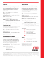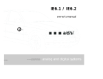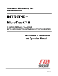
1
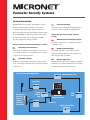
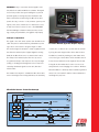
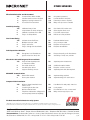
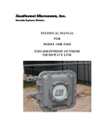
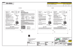
TM
Perimeter Security System
The Next Generation Perimeter Security System
ICRONET™ combines patented Southwest Microwave
Features:
technology with microprocessor power and laptop computer
convenience. It is a sophisticated perimeter security
system which provides precise location of alarms.
from wind, rain or heavy vehicles. Reliable detection is assured.
MICRONET also transmits alarm signals and operating power to all
MICRONET modules and auxiliary sensors along the perimeter eliminating
Sensitivity Leveling for varying
fence conditions
Free Format Zoning eliminates
hardware constraints in
system design
Point Impact Discrimination
increases detection without
increasing nuisance alarms
MicroPoint cable with
integrated power and data for
reduced installation costs
Windows® based PC installation
allows proprietary digital signal processing (DSP) algorithms to detect
any attempt to cut or climb the fence while ignoring distributed noise
MicroPoint Detection with
location to 10 feet
MICRONET is based on MicroPoint™ cable technology which detects
any fence disturbance and locates it to within 10 feet. Precise location
the need for extra wiring. MICRONET software interfaces directly with a personal computer (PC) so that your computer becomes the installation test
set, graphic map, and alarm monitoring display. Installed cost is very low!
Best of all, MICRONET was designed by Southwest Microwave, and
it is backed by our 30 years experience with exterior security systems
around the world.
TM
Perimeter Security Systems
System Description
MICRONET MicroPoint cable is tie wrapped to a chain
Free Format Zoning
link fence where it detects vibrations from any cut
Zones are set from the keyboard, independent of
or climb and precisely locates the point of intrusion.
processor location and may be changed at will.
MicroPoint cable transmits alarm data and system status
to each MICRONET module and provides power to these
modules and auxiliary sensors along the perimeter.
No other equipment or wiring is needed.
Built-in microprocessor and PC software
provide:
Windows based installation program
Installation and service is completed with easy to
Precise location of each fence disturbance provides:
Point Impact Discrimination
use graphic tools.
Graphic annunciator map
Sensitive to a localized fence disturbance caused by a
User drawn site map is converted into a basic
cut or climb. Insensitive to distributed fence noise due
graphic annunciator map. No other multiplexer or
to wind, rain and nearby vehicles.
map display system is needed.
Sensitivity Leveling
Remote diagnostics
Calibration automatically compensates for fence varia-
Modem interface reports site conditions and alarm
tions. Each meter of perimeter fence is equally sensitive
information over ordinary telephone lines. This fea-
to intrusions.
ture allows for remote trouble shooting.
Typical System Configuration
Signal Control Unit
Link Unit
Microwave
Auxiliary
Sensors
(Power
and Data
Provided)
Signal
Control
Unit
MICRONET
Graphic Display
Link
Unit
DC Power
Link Unit
Signal Control Unit
MICRONET’s major components are the Signal Control
Unit, MicroPoint cable and Windows software. The Signal
Control Unit provides the system intelligence to perform
powerful signal processing, DC power distribution and
data communications networking. The MicroPoint cable
permits the easy connection of the perimeter system providing: DC power, data communication for alarms and control,
as well as an intrusion detection sensor. The MICRONET
Perimeter Manager software included provides; site design, step by step installation, and graphic map display.
Principle of Operation
The signal control unit sends a pulse down the MicroPoint
Perimeter Monitor (Operator Graphic Display)
cable. The pulse is reflected back by a disturbance providing location of the intrusion along the length of cable.
The received signal is sampled to create a signature which
of each (3 ft.) of cable is set to provide uniform sensitiv-
describes the reflected pulse. Digital Signal Processing
ity along the entire length of MicroPoint cable. In fence
(DSP) allows MicroPoint sensor to measure the location
installations, Sensitivity Leveling accommodates varia-
and shape of the reflected pulse. The microprocessor
tions in the type of fence fabric and in the fabric tension.
recognizes the shape of the response from a point target
Zones are user defined from the keyboard. Free Format
(cutting or climbing) and distinguishes it from responses
Zoning allows the number and location of zones to be
caused by distributed signals such as rain, wind and
easily altered to meet changing site conditions. Windows
vehicle traffic.
based installation software provides installation guidance
The installer uses any PC to calibrate the MicroPoint cable
and records “as installed” details for later maintenance
sensor and assign zones. During calibration, the sensitivity
and diagnostic purposes.
MicroPoint Sensor - Detection Concept
A
MicroPoint Cables
B
l
Intrusion
Pulse
TX
RX
PULSE
LOGIC
ADC
Response
Digitized Response
MICROPROCESSOR
Range Cells
MicroPoint Sensor
Filtered Response
Intrusion Location
OTHER SENSORS
MicroPoint
Detection and Assessment
YES
Locates alarms within 10 feet
✔
Intruder stands out from wind/rain
✔
Digital processing increases Pd
✔
Focused CCTV assessment
NO
NO
$$$
$$$
Only detects presence
Intruder buried in wind/rain
External processors required
Many more processors needed
Sensitivity
Leveling
YES
✔
✔
✔
Calibrated every 3 feet
Compensates for fence variations
Calibration optimizes Pd vs FAR
Easy to locate problems
NO
$$$
NO
$$$
One threshold for entire zone
Often requires fence work
Pd vs FAR compromised
Difficult to locate problems
Software Controlled Zones
Multiple zones per cable
Easy to add zones
Easy to change zone boundaries
NO
NO
$$$
$$$
Hardware defined zones
Only 1 zone per cable
Requires more processors
Requires reinstallation
YES
Recognizes local disturbances
✔
Ignores noise from wind, rain
MicroPoint cable with Integrated Power and Data
NO
NO
Responds equally to all disturbances
Sensitivity to wind, rain, vehicles
YES
✔
✔
✔
NO
Separate power & data wires
$$$
$$$
$$$
Additional material & labor
Requires conduit to secure
Separate power and data required
NO
$$$
Separate wiring required
Separate wiring from each sensor
NO
User Manual is rarely read, often lost
$$$
NO
$$$
Costly repairs
Documentation is lost or never read
Many unnecessary trips to site
Free Format Zoning
YES
✔
✔
✔
Point Impact Discrimination
Power & Data Superimposed on Transducer Cable
One cable carries all
Secured by the sensor
Supports auxiliary sensors
MICRONET Communications
YES
✔
Built-in FSK network
Peer to peer network
Computer Aided Installation
YES
✔
✔
✔
Windows based Installation and Service Tools
Install it right the first time
Well documented sites
Telephone maintenance & diagnostics
remote upload/download capability
The Next Generation Perimeter Security System.
* MICRONET technology is patented by Southwest Microwave, Inc. (US #5446446) • MICRONET and MicroPoint are trademarks of
Southwest Microwave, Inc. and Windows is a registered trademark of Microsoft Corporation. Specifications subject to change without notice.
Southwest Microwave, Inc.
www.southwestmicrowave.com
9055 South McKemy Street - Tempe, Arizona 85284-2946 USA • Telephone 480-783-0201 • FAX 480-783-0401
European Offices: Southwest Microwave Ltd. • Suite 1, Deer Park Business Centre • Woollas Hill, Eckington, Pershore,
7/06
Worcestershire • WR10 3DN, UK • TEL: +44 (0) 1386 75 15 11 • FAX: +44 (0) 1386 75 07 05
TM
Perimeter Security Systems
System Specifications
System Components
Signal Control Unit
MicroPoint™ Detection locates intrusions
to within 3 meters (10 feet).
Each module processes data from two lengths of MicroPoint cable (A and B). Each length of transducer cable can
Point Impact Discrimination recognizes and
suppresses distributed disturbances due to wind,
rain and vibrations.
be up to 200 meters (650 ft) long. Both A and B lengths
of transducer cable are terminated in either Link Units
or Termination Units.
Sensitivity Leveling automatically compensates
Size:
for fence variations to equalize entire perimeter.
Weight: 7 kg (15.5 lb)
Free Format Zoning allows the zones to be set
Operating Temperature: -40oC to 70oC (-40oF to 159oF)
in software independent of cable length or
equipment location.
Power: 10.5 to 60 VDC at 3.5 watts (without auxiliary sensors)
12 VDC at 580 ma, 24 VDC at 260 ma and
48 VDC at 160 ma
MicroPoint cable provides detection, power
distribution and data communications for the
entire system.
Windows® based MICRONET Perimeter Manager
with Drawing Tool and Installation and
Service Tool included.
MICRONET Map software with precise intrusion
location displayed in color graphics.
Auxiliary sensors and devices are powered and
Inputs:
35.5 L x 30.5 W x 15.3H cm (14 x 12 x 6 in)
2
6
3
4
MicroPoint cables (A and B)
Dry contacts inputs
Analog inputs (0-5 V)
Alarms and 2 Tampers from the Link Units over the MicroPoint cable
Outputs: 3 Alarm relays SPDT (Form C) - 2 amp @ 28 VDC
+12 VDC at 150 ma for auxiliary sensors.
Communications port for computer or relay models.
(with optional 232 or 422A Adapter)
MicroPoint Cable MC-115
controlled by the system.
The MicroPoint cable is used for detection, power distribution and data communications.
Each Signal Control Unit protects up to 1310 Feet MC-115 Type
(1/4 mile), (400 meters) of perimeter.
Size:
4.902 mm (0.193 in) diameter
Multiple Signal Control Units can be connected
Jacket: High density polyethylene, UV resistant, black.
together for larger lengths of perimeter.
Operating Temperature: -40oC to 70oC (-40oF to 159oF)
Operating voltage range (10.5 - 60 VDC)
Minimum Bend Radius: 10 cm (4 in)
Temperature range -40 C to 70 C (-40 F to 159 F).
o
o
o
o
Packaged:
Roll Size
100m (328 ft)
200m (656 ft)
Weight
4kg (9 lbs)
8kg (18 lbs)
Link Unit
Relay Module
Link Units terminate the detection process and provide
Relay Modules communicate via RS485 to the Signal
a means of interconnecting multiple Signal Control Units.
Control Unit with a Network Interface Module. It provides
They are used at the ends of the A and B MicroPoint
both NO and NC relay contacts and analog channels
cables. They also provide terminals to interface to
for external alarm panels, auxiliary controls or remote
auxiliary sensors.
devices. Multiple Relay Modules can be connected
Size:
(up to 10) to the RS 485 line.
35.5L x 30.5W x 15.3H cm (14 x 12 x 6 in)
Weight: 7kg (15.5 lbs)
Size:
Operating Temperature: -40oC to 70oC (-40oF to 159oF)
Weight: 1.36 kg (3 lbs)
Inputs: 2 MicroPoint cables
4 Isolated contacts
Operating Temperature: -40oC to 70oC (-40oF to 159oF)
Power: 10.5 to 13 VDC at 2.0 watts (110 ma)
Outputs: +12 VDC at 150 ma for auxiliary sensors
and devices (optional with Power Converter Card)
Optional Isolated Link Unit:
Used on larger systems (please consult factory)
Termination Unit
The Termination Unit is used at the end-of-line in an open
loop configuration to terminate detection process.
Size:
Weight: 0.45 kg (1 lb)
Operating Temperature: -40 C to 70 C (-40 F to 159 F)
o
o
Inputs: 6 Dry contact inputs
4 Analog Inputs (0 - 5 VDC)
RS485 from Network Interface Module
Outputs: 6 Alarm Relays SPDT (Form C) - 2 Amp @ 28 VDC
12 VDC at 150 ma for Auxiliary Sensors
and devices (optional with Power Converter Card)
Accessories:
7.6L x 6.4W x 13.3H cm (3.0 x 2.5 x 5.25 in)
o
33.7 x 12.7 x 13.9H cm (13.25 x 5 x 5.5 in)
o
Inputs: 1 MicroPoint Cable
Heavy Duty DC Power Supplies
MicroPoint Cable Splice Kit
232A or 422A Adapter
for Communication Connection
Power Converter Card
Network Interface Module
The Network Interface Module provides interface points
for external connections to data and graphic displays.
This module provides RS232 and RS422/RS485 data
ports for external communications and real time clock.
Options:
Multiple Map Graphic Display &
Control Software
Armored MicroPoint cables available.
This module plugs into any Signal Control Units.
Operating Temperature: -40oC to 70oC (-40oF to 159oF)
Outputs: RS485 to Relay Module
RS232 or RS422 to PC/modem
Real time clock
RS422 to Converter
Southwest Microwave, Inc.
MICRONET and MicroPoint Cable are trademarks
of Southwest Microwave, Inc. and Windows is
a registered trademark of Microsoft Corporation.
Specifications subject to change without notice.
www.southwestmicrowave.com
9055 South McKemy Street - Tempe, Arizona 85284-2946 USA • Telephone 480-783-0201 • FAX 480-783-0401
European Offices: Southwest Microwave Ltd. • Suite 1, Deer Park Business Centre • Woollas Hill, Eckington, Pershore,
Worcestershire • WR10 3DN, UK • TEL: +44 (0) 1386 75 15 11 • FAX: +44 (0) 1386 75 07 05
7/06