1
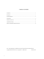
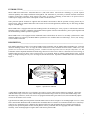
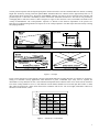
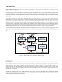
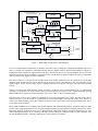
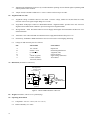
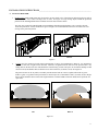
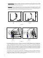
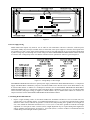
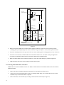
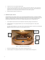
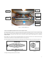
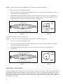
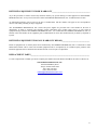
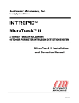
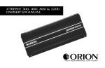
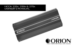
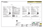
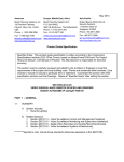
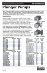
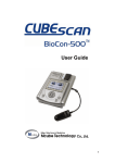
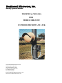
Southwest Microwave, Inc.
Security Systems Division
TECHNICAL MANUAL
FOR
MODEL 300B-33252
OUTDOOR MICROWAVE LINK
SOUTHWEST MICROWAVE, INC
Security Systems Division
9055 South McKemy Street
Tempe, Arizona 85284-2946
Tel: (480) 783-0201
Fax: (480) 783-0401
E-mail: [email protected]
Web: www.southwestmicrowave.com
TABLE OF CONTENTS
Introduction .......................................................................................................................................... 3
Description ........................................................................................................................................... 3
Optional Equipment .............................................................................................................................. 8
Specifications........................................................................................................................................ 9
Installation Instructions ...................................................................................................................... 11
Alignment and Testing ....................................................................................................................... 17
Warranty and Equipment Return Information .................................................................................... 19
Note: This manual applies to installation and set-up of Models 300B-33252 and 300B-33258.
Copyright Southwest Microwave, Inc. August 2007 – 300B-33252™
2
Printed in USA
INTRODUCTION_____________________________________________________________________
Model 300B-33252 Microwave Transmitter-Receiver (T/R) Link utilizes state-of-the-art technology to provide superior
detection capability with simple installation and alignment. The Transmitter is powered by a Gallium Arsenide Field Effect
Transistor (GaAs FET) oscillator, which requires only 20mA (at 12VDC), permitting several links to be powered from a
common power supply located at the control panel or other convenient location.
Three protection pattern elements are supplied with each Model 300-33252B so that the optimum coverage pattern may be
selected at site. Thus any Model 300B-33252 can be used for all T/R Link applications, whether they are short range, medium
range or extended range.
Model 300B-33252 is equipped with universal mounting brackets for mounting to a variety of posts or wall structures. Built-in
alignment voltage test points, compatible with standard VOM, together with four LED indicators, permit quick alignment and
site troubleshooting without special test equipment.
Model 300B-33252 is also equipped with an additional feature which allows the unit to be externally synchronized to other
Southwest Microwave sensors by the Model SMC10 synchronizer. See Technical Note 454. Short range, 10 feet (3m) “slaving”
is also available on this unit.
DESCRIPTION_____________________________________________________________________________________
Each Model 300B-33252 consists of one Model 300B-33252T Transmitter and one Model 300B-33252R Receiver, each with
universal mounting bracket. Note: the High Rel Model 300B-33258 includes RFI/EMI shielded radomes, MB65 heavy duty
position lock corrosion resistant mounting brackets, extended elevated temperature burn-in and full temperature test. The
Transmitter radiates amplitude modulated X-band energy that travels to the receiver where it is detected. The received energy is
amplified and processed so that it causes an alarm relay to be energized. When an intruder approaches the beam, received
energy is changed causing the relay to be de-energized, and an alarm occurs. Operation of Model 300B-33252 is illustrated in
Figure 1.
Figure 1 – Operation of T/R Link
A single Model 300B-33252 may cover a distance up to 600 feet (183m). Three pattern elements are supplied – short range
with maximum range of 100 feet (30m), medium range with maximum range of 350 feet (107m) and extended range with
maximum range of 600 feet (183m). The receiver is equipped with automatic gain-control (AGC) that automatically adjusts
receiver for the distance to be covered.
Typical maximum width protection patterns of Model 300B-33252 are shown in Figure 2 for mounting height of 2.5 feet (.76m)
above smooth earth. Maximum width is attained when Transmitter-Receiver distance is at maximum and Receiver “Sensitivity”
control is set to maximum. Figure 3 illustrates how pattern width varies with Transmitter-Receiver distance and sensitivity
setting for each protection pattern element. Actual patterns will vary somewhat with site topography and surface condition.
Generally, lower mounting height or rougher surface will increase pattern width.
3
Figure 2 – Typical Maximum Horizontal Patterns
10
(3m)
MIN.
100 200 300
400 500 600
(30m) (60m) (90m) (121m)(152m)(183m)
TOTAL LINK DISTANCE - FEET
20
(6m)
5
(1.5m)
MIN.
0
0
50 100 150 200 250 300 350
(15m) (30m) (45m) (60m) (75m) (90m)(107m)
TOTAL LINK DISTANCE - FEET
SHORT-RANGE 100 FEET (30m) - WIDE ANGLE
MAX.
15
(4.5m)
10
(3m)
5
(1.5m)
300B-33252
0
10
(3m)
SENSITIVITY
0
MAX.
15
(4.5m)
MIN.
0
0
20
40
60
80
(6m) (12m) (18m) (24m)
TOTAL LINK DISTANCE - FEET
100
(30m)
Figure 3 – Pattern Width vs. Link Distance and Sensitivity
4
300B-33252
20
(6m)
MID-RANGE 350 FEET (107m)
20
(6m)
SENSITIVITY
SENSITIVITY
30
(9m)
300B-33252
MAX.
NOMINAL BEAM WIDTH - FEET
EXTENDED-RANGE 600 FEET (183m)
40
(12m)
NOMINAL BEAM WIDTH - FEET
NOMINAL BEAM WIDTH - FEET
For example, if the total link distance is 175 feet (53m) with the mid-range antenna pattern element installed and the sensitivity
adjustment set to mid-point, Figure 3 indicates the detection pattern width to be approximately 6 feet (1.8m).
Vertical protection pattern will also depend upon pattern element selected as well as Transmitter-Receiver distance, mounting
height and “Sensitivity” Setting. Protection pattern above Transmitter-Receiver centerline will be approximately half to ¾ of
the horizontal pattern shown above. Protection pattern below centerline will tend to fill area between beam centerline and
ground except for a “dead zone” immediately in front of and below Transmitter and Receiver. This zone is best protected by
overlapping links at ends and corners as shown in Figures 4. Figure 4 show the basic corner, intermediate and basket-weave
overlap recommendations. The overlap distance required is a function of the detection requirement of the specific site.
Detection of a walking/running intruder will require less of an overlap compared to sites that require detection of belly-crawling
and jumping intruders.
Figure 4 – Overlaps
Figure 5 shows amount of overlap required to protect against hands and knees crawling intruders, as a function of “Sensitivity”
setting. For maximum security applications where detection of prone “commando style” belly crawl is required, the
intermediate over-lap should be 50 feet (15m) minimum with parallel beam centerline offset of 18 inches (46cm) maximum.
The corner overlaps should be 25 feet (7.5m) minimum. Terrain flatness should be no more than plus three inches or minus
three inches deviation from a plane drawn between the transmitter and receiver. The zone length (Transmitter to Receiver)
should not exceed 400 feet (121m).
18
(5.4m)
15
(4.5m)
12
(3.6m)
9
(2.7m)
6
(1.8m)
3
(0.9m)
0
DEAD ZONE
COUNTERCLOCKWISE
CLOCKWISE
Figure 5 – “Sensitivity” vs. Dead Zone
5
TRANSMITTER______________________________________________________________________
Model 300B-33252T Transmitter consists of two major subassemblies – RF Assembly and Transmitter Circuit Board. A block
diagram is shown in Figure 6.
The RF assembly consists of a GaAs FET oscillator that generates X-band microwave energy and the parabolic antenna system
with interchangeable protection pattern elements. The transmitter circuit board contains voltage regulator and modulator circuit
to drive the microwave oscillator. Modulation frequency is selected from one of four channels (A, B, C or D) on the transmitter
circuit board.
Two additional features have been added to the Model 300B-33252 transmitter board – a line receiver circuit which allows the
transmitter to be “slaved” to either phase of a master clock and an auxiliary master output for short run, 10 feet (3m) or less,
synchronization of transmitters. In the “slave” position a red LED indicated that the transmitter is “on” providing a check of the
phasing. The phase of the signal can be selected by a PCB jumper to provide either an in phase (0°) or out of phase (180°) clock
reset. This feature is particularly useful in multiple unit installations where mutual interference between mono-static and bistatic sensors can be a problem By proper selection of the phase, units can be alternately turned on or off at the modulation rate.
When the jumper is placed in the “off” position, the Model 300B-33252 reverts back to typical free running operation.
A “test” terminal is provided on the transmitter circuit board. Application of 10.5 to 15.0 VDC (from power supply) will cause
transmitter to turn off, generating a test alarm at receiver. A red “ON” LED on transmitter circuit board indicates that power is
on.
Figure 6 – Model 300B-33252T Transmitter Block Diagram
RECEIVER__________________________________________________________________________
Model 300B-33252R Receiver consists of three major subassemblies – RF Assembly, Demodulator Circuit Board and Power
Supply Board. A block diagram of Model 300B-33252R Receiver is shown in Figure 7. The RF assembly consists of a
parabolic antenna with interchangeable protection pattern elements (identical to antenna of transmitter) and a Schottky diode
detector. The detector converts modulated X-band energy from transmitter into an audio frequency signal for processing by
Demodulator Circuit Board.
The unit also contains a line receiver which allows the receiver to be “slaved” to either phase of an external clock. In this
position, a red LED indicates when the receiver is “on” so that phasing can be checked. When the “slave” jumper is “on” the
normal channel selection feature is overridden.
6
MODULATED ENERGY FROM
X-BAND TRANSMITTER
SCHOTTKY
DETECTOR
ANTENNA
SIGNAL
AMPLIFIER
CHANNEL SELECTION
A
SENSITIVITY
B
C
D
PLL DETECTOR
}
SLAVE
WRONG
CHANNEL
HI
AGC
AMPLIFIER
180 OFF 0
GND
LINE
RECEIVER
LO
FAST
SLOW
NORM
SLOW
ERROR
AMPLIFIER
RCVR
ON
ALIGN
ALARM CIRUIT
NORMAL
JAMMING
ALIGN/LATCH
ALARM
NC
+
12 VDC
-
RELAY
REGULATOR
NO
COM
HOLD-IN
}
ALARM
CONTACTS
RESET
Figure 7 – Model 300B-33252R Receiver Block Diagram
The received audio signal is amplified by an automatic gain control (AGC) preamplifier enabling the preamplifier output to be
held to a constant level regardless of Transmitter-Receiver distance (distance must be within maximum distance of Figure 2).
Preamplifier output is applied to a phase-locked loop (PLL) detector that operates as a narrow bandpass filter at one of the
modulation frequencies. Receive channel is selected by means of PCB jumper to match modulation frequency of Transmitter
while rejecting spurious signals and other Transmitters.
PLL detector output is a voltage level that is held constant under normal conditions by the slow-acting AGC loop. Rapidly
changing signal strength caused by a target moving into the microwave beam is not affected by AGC loop and causes an AC
signal to appear at PLL detector output. Signal is amplified, filtered and compared with upper and lower alarm threshold
voltages.
Whenever signal exceeds either threshold voltage, an alarm is generated. Gain of signal amplifier may be adjusted with
“Sensitivity” potentiometer on circuit board to modify protection patterns per Figures 2 and 3. Signal bandwidth, affecting
Model 300B-33252’s response to fast moving targets, may be set to “Fast” or “Slow” with PCB jumper.
The alarm relay circuit is factory adjusted to automatically reset after approximately two seconds, but hold-in time may be
adjusted between 0.5 and 60 seconds by potentiometer on Power Board Supply. Moving PCB jumper from “Normal” to
“Latch” may defeat automatic reset. In this condition an alarm will cause relay to latch in the alarm position until reset with 515 volt pulse on reset terminal.
Model 300B-33252R Receiver is equipped with various alignment and troubleshooting features. Alignment voltage test point
provides a DC voltage proportional to received signal strength, which may be measured with an ordinary VOM. A red “Alarm”
LED lights whenever an intrusion occurs. A red “Wrong Channel” LED lights whenever Transmitter and Receiver are set to
different modulation channels. A red “Jamming” LED lights whenever Receiver is illuminated with a second Transmitter set to
the same modulation channel. “Jamming” indication may cause an alarm to be initiated.
7
OPTIONAL EQUIPMENT__________________________________________________________________________
Model PS40 Power Supply operates from 110 VAC, 50-60 Hz, and 0.5A and furnishes 13.7 VDC at up to 1.6A @ -40° to +66°
C (-40° to 150° F). The Power Supply contains automatic switchover and battery charging circuitry for optional standby
batteries of up to 25AH. Power supply is fused on both input and output for maximum protection.
Model PS41 Power Supply operates from 220 VAC, 50-60 Hz, and 0.25A and furnishes 13.7 VDC at up to 1.6A @ -40° to
+66° C (-40° to 150° F). The Power Supply contains automatic switchover and battery charging circuitry for optional standby
batteries of up to 25AH. Power supply is fused on both input and output for maximum protection.
Model PS50 Power Supply operates from a 16.5 VAC, 50-60 Hz plug-in transformer Model PT62 (110 VAC) and furnishes
13.7 VDC at up to 0.3A. It is designed for indoor operation, and is conveniently mounted inside a control panel. If mounted
outdoors, it must be in a weatherproof enclosure. Model PS50 will charge a standby battery of up to 7.2AH.
Model PS51 Power Supply operates from a 16.5 VAC, 50-60 Hz plug-in transformer Model PT61 (220 VAC) and furnishes
13.7 VDC at up to 0.3A. It is designed for indoor operation, and is conveniently mounted inside a control panel. If mounted
outdoors, it must be in a weatherproof enclosure. Model PS51 will charge a standby battery of up to 7.2AH.
Model BA30 – 12.6V, 7AH jelly acid, standby battery.
Model RS10 radome provides a shield that encloses Model 300B-33252 circuitry to provide additional protection from
RFI/EMI interference.
Model RS13 radome provides a shield that encloses Model 300B-33252 circuitry to provide additional protection from
RFI/EMI interference plus has Hydrophobic Coating to repel water and ice.
Model RM83 Performance Test Set provides indication of (1) input power supply voltage, (2) alignment, (3) sensitivity and (4)
audio/visual alarm indication. Designed for use with Model 300B-33252. It is recommended for setup and maintenance testing.
Model MB65 Corrosion Resistant Mounting Bracket provides means of locking the angular direction setting of Model 300B33252 Transmitter or Receiver. Model MB65 mounts to 4 inch (10cm) O.D.
Model BX 20 NEMA 4X SS Weatherproof Enclosure. Includes inner panel with Model PS40/PS41 power supply, two 12position terminal strips, one 3-position AC input power shielded terminal strip and mounted tamper switch.
Model 02A15483-A01 Radome Latch Kit replaces screws on radome for quick access to sensor electronics.
Model LF115 Line Filter provides RFI/EMI, transient, surge protection for single microwave transmitter or receiver.
Model SMC10 synchplexer module allows crystal controlled selection for synchronization to Model 375C transceivers or other
synchronized capable links. The board is equipped with a line driver and is capable of slaving up to 8 units over a 1000 foot
(305m) distance. Reference: Technical Note # 454.
Model CRP heavy duty corrosion resistant package, per MIL Spec A-8625D, P-15328.
8
SPECIFICATIONS_____________________________________________________________________________
1.0
2.0
3.0
4.0
5.0
Detection Capability
1.1
Range: 10 feet (4.6m) to 600 feet (183m).
1.2
Beam Diameter: 2 feet (.6m) to 40 feet (12.2m) depending upon link length, antenna pattern element and
“Sensitivity” setting per Figure 3A, 3B, 3C.
1.3
Target: 77 pound (35kg) human walking, running, hands and knees crawling and jumping. Prone crawling or
rolling 77 pound (35kg) human or simulated with a 12 inch (30cm) diameter metal sphere, detected at maximum
range of 400 feet (122m).
1.4
Minimum Target Velocity: 0.1ft. /sec. (3cm/sec.)
1.5
Maximum Target Velocity: 10ft. /sec. (3m/sec.) slow setting, 50 ft. /sec. (15m. /sec.) fast setting.
Reliability
2.1
Equipment False Alarm Rate: 1/year/unit based upon signal-to-noise ratio at maximum sensitivity setting.
2.2
Probability of Detection: 0.9 minimum on 77-pound (35kg) human upright or on hands and knees.
2.3
Self Supervision (Alarm on Failure): Inherent in design (fully self-supervised).
2.4
Automatic Gain Control: Receiver sensitivity automatically adjusts to slow changes in environment. AGC range
54dB.
2.5
Cross Modulation: When installed in accordance with following installation instructions cross modulation
(interference) from adjacent links will be 25dB below primary signal.
Transmittal Signal
3.1
Radiated Power: 10 mill watts peak, 5 mill watts average, square wave modulated.
3.2
Carrier Frequency: X-band (USA 10.525 GHz + 25MH).
3.3
Modulation Frequencies: Four field-selectable modulation frequencies.
3.4
Above specifications for USA are in accordance with F.C.C. regulations. Equipment available to meet regulations
of other countries.
Power Requirement
4.1
Voltage: 10.5 to 14.0VDC
4.2
Current: 20mA Transmitter, 20mA Receiver under normal ambient operating conditions.
4.3
Transmitter fused for 0.25 amps and Receiver each fused for 0.25 amps.
Alarm Indication
5.1
Alarm Relay Contacts: Primary alarm indications provided by normally open contact, normally closed contact and
common terminal (Form C), contact rating 2 amps at 28VDC.
5.2
Walk Test LED: Secondary alarm indication provided by red LED on Receiver Power Supply Board.
9
6.0
5.3
Jamming LED: Illumination of Receiver by second Transmitter operating on same channel lights red jamming LED
and may initiate alarm condition.
5.4
Tamper Switch, Transmitter and Receiver: Form C contacts rated 2.0 Amp at 28 VDC.
Alignment and Test Aids
6.1
Alignment Voltage: Available at Receiver Test Point 1. Positive voltage, suitable for 100,000 ohms/volt VOM,
increases with receiver signal strength. Range 0.5-5.0 VDC.
6.2
Align Mode: PCB jumper on Receiver Demodulator Board. “Alignment Mode” provides faster AGC action for
alignment and constant alarm condition to prevent leaving link in Alignment Mode.
6.3
Wrong Channel – LED: Red LED on Receiver Power Supply Board lights when Transmitter and Receiver set to
different channels.
6.4
Transmitter “ON” LED: Red LED on Transmitter Power Supply Board indicates that power is on.
6.4
Alternatively, the RM82 or RM83 Performance Test Set can be used to aid in aligning and testing.
6.5
Voltages on MS connector pins are as follows:
PIN
A
B
C
D
E
F
7.0
VOLTAGES
FUNCTIONS
10.5 -14VDC
8.0VDC + 0.5V
0.5 Minimum
0
3-4VDC (Typical)
0.1VDC (Normal)
10-12VDC (Alarm)
Input Power
Internal Regulated Power
Alignment (TPI)
Chassis Ground
Signal Voltage (Intrusion)
Alarm Status
Dimensions (Transmitter or Receiver)
Mounting Holes
4.5 in (11.4cm)
2.3 in (5.9cm)
3.5 in.
(8.9cm)
10.6 in.
(27cm)
Dia.
20o MAX TILT
ANY DIRECTION
6.0 in.
(15.2cm)
Figure 8 – Model 300B Transmitter or Receiver
8.0
Weight, Transmitter, or Receiver: 4.5 pounds (2kg).
9.0
Operating Environment
10
9.1
Temperature: -40° F to +150° F (-40° C to +66° C)
9.2
Relative Humidity: 0 to 100%.
INSTALLATION INSTRUCTIONS______________________________________________________
A. Location of Model 300B
1.
Required Area. Mode 300B-33252 must be located in an area which is free of obstructions and moving objects such as
chain link fences, trees, bushes and large areas of water. See Figure 9. Large moving objects within the protection
pattern will be indistinguishable from an intruder and will cause nuisance alarms.
The clear area required for a Model 300B-33525 installation depends upon the distance to be covered by the link.
Protection patterns for various conditions are given in Figures 9. In each installation the clear area must be at least
as large as the protection pattern.
DO
DON’T
Figure 9
2.
Terrain. Since the operation of Link requires transmission of energy from Transmitter to Receiver, it is important to
maintain a clear line of sight between the units. Therefore, the ground must be flat across the protected area. Any
bumps, hills or ditches in the area will shadow the beam and may provide crawl space for an intruder. Bumps or hills
must be leveled, and ditches filled so that the area is flat to within six (6) inches (15cm). See Figure 10.
The protected area can be any stable, reasonably smooth material such as concrete, asphalt, tilled earth or gravel.
If there is grass or vegetation in the protected are it must be kept cut to a maximum of three (3) inches (8cm) in height
Snow removal should be done at this same height limitation. A Model 300B-33252 Link should not be operated over
open water.
DO
DON’T
Figure 10
11
3.
Physical Protection. Install the Transmitter and Receiver in locations that provide protection from accidental
damage as well as from tampering. Simple devices such as bumper posts or parking guards may be used to protect
equipment from damage from vehicles. See Figure 11.
4.
Best Security. Choose the location that will provide best security, yet be free from false alarms. Always locate
Model 300B-33252 inside a controlled access area to prevent unwanted alarms due to random foot traffic, vehicles,
or large animals. Typically, units should be mounted two and one-half to three feet (0.75-1.0m) above ground level,
and far enough inside fence to provide a clear area of protection. See Figures 12 & 13.
DO
DON’T
Figure 11
2 to 3 Feet
(.61 to 1.0m)
6 to 10 Feet (1.9 to 3.1m)
DO
DON’T
Figure 12
For maximum security it is necessary to overlap the ends of links so that the dead spot below and immediately in
front of the adjoining link is protected. This type of location gives maximum possible security. A 30-foot (9m)
overlap is recommended at intermediate points, and a 15-foot (4.6m) overlap is recommended at corners for
minimum and medium security applications. If site demands shorter overlap, increased sensitivity will reduce dead
zone, per Figure 5, but will also widen beam, per Figure 3.The offset of overlapping links in line should be measured
from center of each unit (See Figure 4). Additional protection may be added at critical points by installing
SOUTHWEST MICROWAVE, INC. Model 380 or 385 Monostatic Sensors, Model 405 Passive Infrared Sensor,
Model MS15 or MS16 Dual Technology Sensors or stacked links.
Note form Figure 13 that at each point of overlap, either two Transmitters or two Receivers should be installed. This
arrangement prevents an adjacent Transmitter and Receiver from establishing an unwanted link across the short
overlap distance. If there is an odd number of links in an installation, a transmitter and receiver will need to be
overlapped. This should be done in a corner as shown in Figure 13
12
Figure 13
B. Power Supply Wiring
Model 300B-33252 requires only 20mA at 10.5-14 VDC for each Transmitter or Receiver. Therefore, sufficient power
with battery standby may already be available at the site from other sensor power supplies or from the control panel itself.
Any regulated “12 VDC” power supply will be adequate so long as noise and transients do not exceed 50mV and attention
is paid to voltage drop in connecting wires so that voltage AT EACH TRANSMITTER OR RECEIVER remains between
10.5 and 14 VDC. Voltage drop versus wire distance in normal or slave operation for 500 feet is given in Figure 14.
Figure 14 – Voltage Drop vs. Wire Gauges
SOUTHWEST MICROWAVE offers two optional power supply combinations. Model PS50/Model PS51, 0.3 Amp Power
Supply with Model BA30 7AH Battery will power one Model 300B-33252 T/R Link in slave mode. Model PS50/51 may
be located either indoors or outdoors in a weatherproof enclosure such as SOUTHWEST MICROWAVE Model BX15.
Model PS40/Model PS41, 1.6 Amp Power Supply with Model BA30 7AH Battery will power up to five Model 300B33252 T/R Links (with proper wiring per Figure 15). Model PS40/41 may be mounted either indoors or outdoors in a
rainproof enclosure such as SOUTHWEST MICROWAVE Model BX20 or BX35.
C. Mounting Model 300B T/R Link
1.
Prepare a rigid mounting surface for the Model 300B-33252 Transmitter and Receiver. Do not mount units on a
cyclone fence or any vibrating surface. A recommended mounting post is a 3½ inch (9cm) galvanized pipe (outside
diameter 4 inches, 10cm), sunk into the ground in a concrete base, and protruding above ground level to a height of 4
feet (1.2m). Mount the Transmitter and Receiver 2½ to 3 feet (0.75 to 1.0m) above ground level and allow for height
adjustment of at least plus or minus 12 inches (30cm). Height adjustment may be required during final alignment to
achieve optimum protection pattern. See Figure 15. An 18-inch (46cm) ½ inch flex conduit is recommended between
conduit fitting of T/R and rigid conduit or junction box.
13
Cap
4" O.D.
Galvanized Pipe
Gnd. Lug &
Wire
1/2" x 18"
Flexible
Conduit
48"
36"
Nominal
Ground Lug
#6 AWG
GROUND BUS
Concrete
24" Deep x 18"
to 24" Square
Typical
Grounding Rod
per Local
Electrical Code
Tamper, Alarm and Power Lines
Figure 15
2.
Remove the Model 300B-33252 T/R Link from the shipping containers. Separate the swivel assembly from the
mounting plate by turning the large nuts counter-clockwise. Large nuts require 1 ¼ inch (32mm) open-end wrench.
3.
Secure the mounting bracket to the post with U-bolt or to other mounting surface with appropriate screws or fasteners.
4.
Secure the swivel assembly to Model 300B-33252 Transmitter and Receiver. The rubber washer goes against the
center hub of the baseplate followed by the metal washer and attach to mounting bracket.
5.
Rotate the Model 300B-33252 Transmitter and Receiver so that the conduit fittings are pointed straight down.
6.
Tighten the large nuts on the swivel assembly to hold the units in place.
D. Connecting Model 300B-33252T Transmitter
Caution: DO NOT APPLY POWER UNTIL ALL WIRE CONNECTIONS HAVE BEEN MADE. SEE FOLLOWING
INSTRUCTIONS.
14
1.
Remove the radome of Model 300B-33252 Transmitter by removing the six-radome screws.
2.
Insert power wires and optional tamper circuit wires through conduit fitting. Leave enough slack in wires so that
Transmitter may be tilted after radome is replaced.
3.
Make connections to the terminal strip according to labeled terminal functions (See Figure 16).
Figure 16 – Wiring Diagram
4.
Attach power wires to terminal identified as + (Positive) and - (Negative) Input 12 VDC. Observe Polarity.
5.
For protection against unauthorized openings or tampering, a tamper switch with a separate set of contacts is
provided. Form C contacts (normally open, normally closed and common) are available at the Tamper Switch
terminals.
6.
Connect remote test wire, if used, to Test terminal on strip.
7.
Connect wires to HI, LO and GND, if used, at Slave terminals. Set the “Phase” jumper to the “OFF” position or if
using the external clock (SMC10) set to the proper phase. When the unit is in the “Slave” mode the channel select
jumper must be in the external position. Refer to Technical Note 454 for SMC10 operation.
8.
Reinstall the radome using the six radome screws.
E. Connecting Model 300B-33252R Receiver
1.
Remove radome of Model 300B-33252R Receiver by removing the six-radome screws.
2.
Insert power wires and alarm circuit wires through conduit fitting. Leave enough slack in wires so that Receiver may
be tilted after radome is replaced.
3.
Make connections to the terminal strip according to labeled terminal functions. (See Figure 16.)
4.
Attach power wires to terminal identified as + (Positive) and - (Negative) Input 12VDC. Observe Polarity.
5.
Attach alarm circuit wires as follows:
CLOSED CIRCUIT ALARM: contacts (open on alarm) available at “Alarm Relay” COM and NC terminals.
OPEN CIRCUIT ALARM: contacts (close on alarm) available at “Alarm Relay” COM and NO terminals.
TAMPER ALARM: contacts available at Tamper Switch terminals. (NO, COM, NC).
15
6.
Connect reset wire, if used, on Reset terminal on strip.
7.
Connect wires to HI, LO and GND, if used, at Slave terminals. Set the “Phase” jumper to the “OFF” position or if
using the external clock (SMC10) set to the proper phase. When the unit is in the “Slave” mode the channel select
jumper must be in the external position. Refer to Technical Note 454 for SMC10 operation.
8.
Reinstall the radome using the six radome screws.
F. Modulation Frequency Selection
The Model 300B-33252T Transmitter features four (4) field selectable modulation frequencies. Use different modulation
frequencies on links operating within close proximity. Different modulation frequencies reduce the possibility of cross-link
modulation or mutual interference. In addition, the transmitters can be “slaved” to an external clock (SMC10) when
interfacing with Southwest Microwave transceivers to eliminate mutual interference. See Technical Note 454.
1.
Select modulation channel different from the modulation of other links operating in the immediate area.
2.
Attach PCB jumper wire to appropriate channel (A, B, C or D). Set the phase jumper to the “OFF” position.
(See Figure 17.)
The Model 300B-33252R Receiver also features four (4) field selectable frequencies. The Receiver and Transmitter
MUST be operated on the same frequency or an alarm condition will result.
Modulation
Frequency
Power
“ON”
LED
Sync
XMTR
“ON”
LED
Phase
Select
Figure 17 – Model 300B-33252T Transmitter
16
3.
Determine the modulation frequency of the Transmitter illuminating the Receiver.
4.
Attach PCB jumper wire to appropriate terminal for the same modulation channel. (See Figure 18.)
Align
Test Point
Sensitivity
Alarm, Wrong
Channel and
Jamming LED
Modulation
Frequency
Align/Latch
- Normal
Phase Select
Sync RCVR
“ON” LED
Figure 18 – Model 300BR Receiver
ANTENNA PATTERN ELEMENT INSTALLATION INSTRUCTIONS________________________________________
Each Model 300B-33252 Microwave Link provides three detection patterns and ranges to 600 feet (183m). The pattern width
may be varied in the field by simply installing the proper antenna pattern element and adjusting receiver sensitivity. Protection
pattern width may be varied from 2 feet (0.6m) to 40 feet (12.2m) wide. (Refer to Figure.) Pattern height varies in conjunction
with pattern width.
Model 300B-33252 is shipped with the EXTENDED RANGE element installed on the front of the antenna feed and secured
with a PLASTIC NYLON screw on both Transmitter and Receiver (See Figure 20).
Note: Initial alignment should be performed with extended range element installed on 300B-33252 Transmitter and Receiver.
Figure 19
Figure 20
To change to mid-range element, proceed as follows:
17
NOTE:
Perform the next four steps on both 300B-33252 Transmitter and 300B-33252 Receiver.
1.
Remove six (6) screws securing plastic radome.
2.
Remove PLASTIC NYLON screw (DO NOT THROW AWAY) from end of antenna feed and remove extended
range element (DO NOT THROW AWAY).
3.
Install MID-RANGE element (double folded disc) and secure with plastic nylon screw from step #2. Mid-range
element can be mounted in the horizontal or vertical position (must be same on Transmitter and Receiver) on the
front of the antenna feed as required for optimum detection. (See Figure 22).
1/2" (1.27cm)
FOLDED
DISC
MID RANGE
5 to 20 FT (1.5 to 6.1m)
ANTENNA
FEED
350 FT. (107m) ANTENNA PATTERN
Figure 21
- HORIZONTAL -
Figure22
To change to short-range element, proceed as follows:
NOTE:
Perform the next four steps on both 300B-33252 Transmitter and 300B-33252 Receiver.
1.
Remove six (6) screws securing plastic radome.
2.
Remove PLASTIC NYLON screw (DO NOT THROW AWAY) from end of antenna feed and remove extended
range element (DO NOT THROW AWAY).
3.
Install SHORT-RANGE element (adhesive copper foil) around outer circumference of the antenna feed.
(See Figure 24)
- HORIZONTAL -ADHESIVE
SHORT RANGE - WIDE ANGEL
FOIL
ELEMENT
5 to 20 FT (1.5 to 6.1m)
100 FT. (30m) ANTENNA PATTERN
Figure 23
ANTENNA
FEED
Figure 24
ALIGNMENT AND TESTING__________________________________________________________
An MS type connector has been added to the rear side of the Receiver baseplate. This connector, when used in conjunction with
SOUTHWEST MICROWAVE Model RM82 or RM82 Link Performance Test Set, will facilitate field alignment and testing of
Model 300B-33252 Microwave Links without removal of radome. The following outline will assist the installer in alignment
and testing of the Model 300B-33252 Microwave Intrusion Link using a VOM (volt-ohm-meter) with an input impedance of
100,000 ohms/volt or greater.
18
1.
With radomes removed, apply power to the Transmitter and Receiver.
2.
Be sure the identical modulation frequency is being used on the Transmitter and Receiver of the Link to be aligned.
Note: The extended range element will help ensure more precise alignment during initial set up.
3.
Check for Transmitter operation by monitoring the Transmitter “ON” LED on the Transmitter Circuit Board. (See
Figure 17)
4.
Visually aim the Transmitter and Receiver for “bore-sight” (pointing at each other) alignment.
5.
Move the Align/Latch – Normal jumper to Latch position. (See Figure 18.)
6.
On Receiver, connect VOM to TP1 (Positive), and E1 GND (Negative), with meter range set to 3-5VDC. (See Figure 18.)
7.
Swivel Receiver up and down, side to side, to obtain maximum meter reading. The front edge of the parabolic dish must be
perpendicular to the ground surface. Tighten locking nut on mounting bracket to secure sensor in this position.
8.
Raise and lower height of Receiver as required for maximum meter reading. This will provide maximum detection
sensitivity.” The minimum alignment voltage for the Model 300B-33252 is 0.5 VDC. Although this is the minimum
voltage, proper alignment and mounting height will typically provide a greater indication on the meter.”
9.
Swivel Transmitter up and down, side to side, to obtain maximum meter reading. The front edge of the parabolic dish must
be perpendicular to the ground surface. Tighten locking nut on mounting bracket to secure sensor in this position. The
minimum alignment and voltage for the Model 300B-33252 is 0.5VDC. Although this is the minimum voltage, proper
alignment and mounting height will typically give a greater indication on the meter.
10. Disconnect VOM and move Align/Latch-Normal jumper to Normal position.
11. Walk test the Link to determine width of pattern, while monitoring alarm indication by means of red “Alarm” LED.
12. Adjust pattern width by changing antenna element or by turning “SENS” potentiometer clockwise to increase and
counterclockwise to decrease, until desired width is obtained. (See Figure 3.)
13. Replace radomes using all six screws.
HIGH SECURITY TEST FUNCTION____________________________________________________
Model 300B-33252 includes a remote test and reset feature for high security applications.
1.
To test the Transmitter, the Power Supply voltage (12VDC) must be applied to terminal “TEST” on the Model 300B33252T. (See Figures 16 and 17).
2.
Testing the Transmitter may be accomplished by momentarily switching “ON” the 12VDC from the Power Supply to the
“TEST” terminal.
3.
When the “TEST” is actuated, the Receiver will alarm. A higher degree of security can be obtained by utilizing the “Latch”
function of the Model 300B-33252R Receiver.
4.
Connect the “Align/Latch – Normal” PCB jumper to “Align/Latch” position. This will cause the Receiver to latch into the
alarm state when either the “TEST” function is used at the Transmitter or an intrusion of the link has occurred.
5.
To reset the link to the normal non-alarm condition, 5-15 VDC must be applied to terminal “Reset” on the Model 300BR.
(See Figures 16 and 18.)
By utilizing both the “Test” and “Reset” functions, the link can be tested and secured from a remote point.
19
PREVENTIVE MAINTENANCE________________________________________________________
Model 300B-33252 requires no calibration other than alignment and sensitivity adjustment during installation. To maintain a
trouble free system the following is recommended.
1.
Wax the radomes every 3 to 6 months. (At maximum security installations, where detection of prone crawling targets is
required, wax once a month.)
2.
Keep the isolation area clean and free of tall grass, weeds, debris, and obstructions.
3.
Upon initial installation, establish a zone data chart. Record input supply voltage, zone distance, transmitter/receiver
mounting height, alignment voltage, modulation channel, sensitivity setting, and battery voltages.
4.
If standby batteries are used, they should be functionally tested every three months.
5.
A site inspection should be performed every six months. The inspection should include: verifying data from Step 3,
checking for physical damage (cracks, leaks, corrosion, etc.) checking for isolation zone changes (washouts, materials
placement, vegetation growth, loose fence fabric, etc.)
For troubleshooting information, please contact the factory about Model 300B-33252 Service Manual.
LIMITED WARRANTY_______________________________________________________________
SOUTHWEST MICROWAVE, INC. warrants each of its products to be free from defects in materials and workmanship. The
limit of liability under this warranty is to repair or replace any products or part thereof which shall within one year after
delivery to the original user be returned, shipping costs prepaid and insured, to SOUTHWEST MICROWAVE, INC. at its plant
in Tempe, Arizona, or authorized Warranty Service Company, and which shall have been found to be defective upon
examination by SOUTHWEST MICROWAVE, INC. or authorized Warranty Service Company.
This warranty shall be limited to the repair or replacement of SOUTHWEST MICROWAVE, INC. products and shall not
extend to any incidental or consequential damages there from. Disassembly of any product by anyone other than an authorized
representative of SOUTHWEST MICROWAVE, INC. voids the obligations of SOUTHWEST MICROWAVE, INC. to repair
or replace any products so disassembled.
Excluded from this warranty are fuses and batteries except to the extent that the original manufacturer warrants such parts and
such warranty is marked on the product. Claim under warranty for fuses or batteries should be made by the purchaser directly to
the manufacturer.
Warranty returns must first be authorized by SOUTHWEST MICROWAVE, INC. or authorized Warranty Service Company.
SOUTHWEST MICROWAVE, INC. reserves the right to make changes in design on any of its products without incurring any
obligation to make the same changes on units previously purchased.
THIS WARRANTY IS THE EXTENT OF THE OBLIGATIONS OR LIABILITIES ASSUMED BY SOUTHWEST
MICROWAVE, INC. WITH RESPECT TO ITS PRODUCTS AND IS IN LIEU OF ALL OTHER WARRANTIES, EXPRESS
OR IMPLIED, INCLUDING, BUT NOT LIMITED TO, ANY WARRANTY OF MERCHANTABILITY OR FITNESS.
SOUTHWEST MICROWAVE, INC. SHALL NOT BE LIABLE FOR CONSEQUENTIAL DAMAGES AND ITS
LIABILITY IS EXPRESSLY LIMITED TO THE OBLIGATIONS EXPRESSED HEREIN. SOUTHWEST MICROWAVE,
INC. NEITHER ASSUMES NOR AUTHORIZES ANY OTHER PERSON TO ASSUME FOR IT ANY OTHER
WARRANTY CONCERNING ITS PRODUCTS.
20
RETURNING EQUIPMENT UNDER WARRANTY________________________________________
As per the provisions set forth in our Security Products warranty, any person desiring to return equipment to SOUTHWEST
MICROWAVE, INC. for any reason, must first contact SOUTHWEST MICROWAVE, INC. for authorization of return.
An authorization number will be issued at the time of authorization, and this number will appear on all correspondence,
invoices and credits pertaining to subject equipment.
ALL SOUTHWEST MICROWAVE, INC. sensors and power supplies are provided with a serial number at the time of
manufacture. In order to accurately and efficiently supply replacement parts, perform repair service, or issue credit on
equipment being returned to SOUTHWEST MICROWAVE, INC., it is essential that SOUTHWEST MICROWAVE, INC. be
advised of the serial number of the equipment prior to authorization for return. This notification may be made by telephone or
by mail.
RETURNING EQUIPMENT FOR NON-WARRANTY REPAIR_____________________________
Return of equipment out of warranty must first be authorized by SOUTHWEST MICROWAVE, INC. at which time a return
authorization number will be issued. The returned equipment must be accompanied by an evaluation repair purchase order.
Returned equipment will be examined and customer advised of cost of repair or replacement.
REPLACEMENT PARTS______________________________________________________________
To order a replacement or module, specify the complete part number and serial number and address the order or contact us at:
SOUTHWEST MICROWAVE, INC.
9055 South McKemy Street
Tempe, Arizona 85284-2946
TEL: (480) 783-0201
FAX: (480) 783-0401
[email protected]
www.southwestmicrowave.com
21