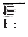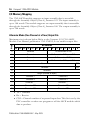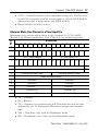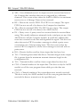
1
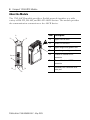
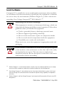
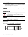
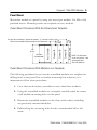
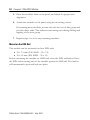
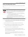
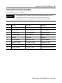
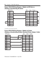
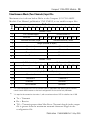
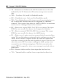
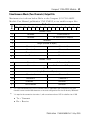
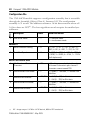
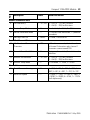
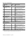
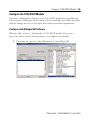
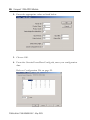
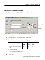
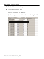
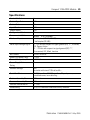
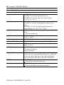
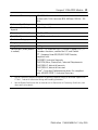
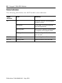
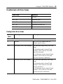
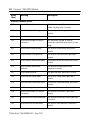
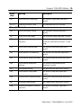
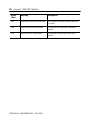
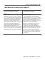
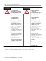
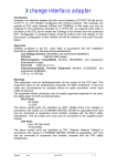
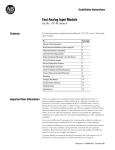
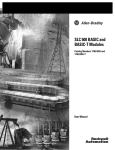
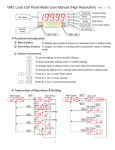
Installation Instructions
Compact 1769-ASCII Module
Cat. No. 1769-ASCII
Inside…
About the Module ............................................................................................4
Install the Module.............................................................................................5
Assemble the System........................................................................................6
Mount Expansion I/O ....................................................................................8
Ground the Module........................................................................................12
Connect the D-sub Connector Pins ............................................................13
I/O Memory Mapping...................................................................................16
Configure the 1769-ASCII Module .............................................................25
Specifications...................................................................................................29
Status Indicators..............................................................................................32
Troubleshoot with Error Codes ...................................................................33
Publication 1769-IN068B-EN-P - May 2005
2 Compact 1769-ASCII Module
Important User Information
Because of the variety of uses for the products described in this publication,
those responsible for the application and use of these products must satisfy
themselves that all necessary steps have been taken to assure that each
application and use meets all performance and safety requirements, including
any applicable laws, regulations, codes and standards. In no event will
Rockwell Automation be responsible or liable for indirect or consequential
damage resulting from the use or application of these products.
Any illustrations, charts, sample programs, and layout examples shown in this
publication are intended solely for purposes of example. Since there are many
variables and requirements associated with any particular installation,
Rockwell Automation does not assume responsibility or liability (to include
intellectual property liability) for actual use based upon the examples shown in
this publication.
Allen-Bradley publication SGI-1.1, Safety Guidelines for the Application,
Installation and Maintenance of Solid-State Control (available from your local
Rockwell Automation office), describes some important differences between
solid-state equipment and electromechanical devices that should be taken into
consideration when applying products such as those described in this
publication.
Reproduction of the contents of this copyrighted publication, in whole or
part, without written permission of Rockwell Automation, is prohibited.
Throughout this publication, notes may be used to make you aware of safety
considerations. The following annotations and their accompanying statements
help you to identify a potential hazard, avoid a potential hazard, and recognize
the consequences of a potential hazard:
WARNING
ATTENTION
Identifies information about practices or circumstances that can
cause an explosion in a hazardous environment, which may lead
to personal injury or death, property damage, or economic loss.
Identifies information about practices or circumstances that can
lead to personal injury or death, property damage, or economic
loss.
Publication 1769-IN068B-EN-P - May 2005
Compact 1769-ASCII Module 3
IMPORTANT
ATTENTION
Identifies information that is critical for successful application
and understanding of the product.
Environment and Enclosure
This equipment is intended for use in a Pollution Degree 2
industrial environment, in overvoltage Category II applications
(as defined in IEC publication 60664-1), at altitudes up to 2000
meters without derating.
This equipment is considered Group 1, Class A industrial
equipment according to IEC/CISPR Publication 11. Without
appropriate precautions, there may be potential difficulties
ensuring electromagnetic compatibility in other environments
due to conducted as well as radiated disturbance.
This equipment is supplied as “open type” equipment. It must
be mounted within an enclosure that is suitably designed for
those specific environmental conditions that will be present and
appropriately designed to prevent personal injury resulting from
accessibility to live parts. The interior of the enclosure must be
accessible only by the use of a tool. Subsequent sections of this
publication may contain additional information regarding
specific enclosure type ratings that are required to comply with
certain product safety certifications.
NOTE: See NEMA Standards publication 250 and IEC
publication 60529, as applicable, for explanations of the degrees
of protection provided by different types of enclosure. Also, see
the appropriate sections in this publication, as well as the
Allen-Bradley publication 1770-4.1 (“Industrial Automation
Wiring and Grounding Guidelines”), for additional installation
requirements pertaining to this equipment.
Publication 1769-IN068B-EN-P - May 2005
4 Compact 1769-ASCII Module
About the Module
The 1769-ASCII module provides a flexible network interface to a wide
variety of RS-232, RS-485, and RS-422 ASCII devices. The module provides
the communication connections to the ASCII device.
Item Description
1a
2a
2a
3a
1a
Upper DIN rail latch
1b
Lower DIN rail latch
2a
Upper tongue-and-groove slots
4 2b
Lower tongue-and-groove slots
3a
Channel 0 isolated ASCII
connector
3b
Channel 1 isolated ASCII
connector
4
Stationary bus connector with
male pins
3b
2b
2b
1b
Publication 1769-IN068B-EN-P - May 2005
Compact 1769-ASCII Module 5
Install the Module
Compact I/O is suitable for use in an industrial environment when installed
in accordance with these instructions. Specifically, this equipment is intended
for use in clean, dry environments (Pollution Degree 2(1)) and to circuits not
exceeding Over Voltage Category II(2) (IEC 60664-1).(3)
ATTENTION
Preventing Electrostatic Discharge
This equipment is sensitive to electrostatic discharge, which can
cause internal damage and affect normal operation. Follow these
guidelines when you handle this equipment:
• Touch a grounded object to discharge potential static.
• Wear an approved grounding wriststrap.
• Do not touch connectors or pins on component boards.
• Do not touch circuit components inside the equipment.
• If available, use a static-safe workstation.
When not in use, store the equipment in appropriate static-safe
packaging.
WARNING
If you connect or disconnect the serial cable with power applied
to this module or the serial device on the other end of the cable,
an electrical arc can occur. This can cause an explosion in
hazardous locations. Be sure that power is removed or the area is
nonhazardous before proceeding.
(1)
Pollution Degree 2 is an environment where, normally, only non-conductive pollution occurs except
that occasionally a temporary conductivity caused by condensation shall be expected.
(2)
Over Voltage Category II is the load level section of the electrical distribution system. At this level
transient voltages are controlled and do not exceed the impulse voltage capability of the product’s
insulation.
(3)
Pollution Degree 2 and Over Voltage Category II are International Electrotechnical Commission (IEC)
designations.
Publication 1769-IN068B-EN-P - May 2005
6 Compact 1769-ASCII Module
ATTENTION
This product is grounded through the DIN rail to chassis
ground. Use zinc-plated, yellow-chromate steel DIN rail to
assure proper grounding. The use of other DIN rail materials
(e.g., aluminum, plastic, etc.), which can corrode, oxidize, or are
poor conductors, can result in improper or intermittent
grounding.
Assemble the System
Attach the module to the controller or an adjacent I/O module before or
after mounting. For mounting instructions, see the Panel Mount or Mount on
the DIN Rail sections. To work with a system that is already mounted, see
Replace a Single Module Within a System section.
3
4
2
1
6
1
5
Publication 1769-IN068B-EN-P - May 2005
Compact 1769-ASCII Module 7
1. Disconnect power.
ATTENTION
Remove power before removing or inserting this module. When
you remove or insert a module with power applied, an electrical
arc may occur. An electrical arc can cause personal injury or
property damage by:
• sending an erroneous signal to your system’s field devices,
causing unintended machine motion
• causing an explosion in a hazardous environment
Electrical arcing causes excessive wear to contacts on both the
module and its mating connector. Worn contacts may create
electrical resistance.
2. Check that the bus lever of the module to be installed is in the
unlocked (fully right) position.
3. Use the upper and lower tongue-and-groove slots (1) to secure the
modules together or to a controller.
4. Move the module back along the tongue-and-groove slots until the
bus connectors (2) line up with each other.
5. Use your fingers or a small screwdriver to push the bus lever back
slightly to clear the positioning tab (3).
6. To enable communication between the controller and module, move
the bus lever fully to the left (4) until it clicks.
Ensure it is locked firmly in place.
ATTENTION
When attaching I/O modules, it is very important that the bus
connectors are securely locked together to ensure proper
electrical connection.
Publication 1769-IN068B-EN-P - May 2005
8 Compact 1769-ASCII Module
7. Attach an end-cap terminator (5) to the last module in the system by
using the tongue-and-groove slots as before.
8. Lock the end-cap bus terminator (6).
You must use a 1769-ECR or -ECL right- or left-end cap to
terminate the end of the serial communication bus.
IMPORTANT
Mount Expansion I/O
ATTENTION
During panel or DIN rail mounting of all devices, be sure that all
debris (metal chips, wire strands, etc.) is kept from falling into
the module. Debris that falls into the module could cause
damage on power up.
When mounting the CompactLogix system, either use screws
to panel mount the system OR use DIN rail. Do NOT use
both. Use of both mounting methods may cause hardware
damage and cause the system to fail.
IMPORTANT
Minimum Space
Maintain spacing from enclosure walls, wireways, adjacent equipment, etc.
Allow 50 mm (2 in) of space on all sides for adequate ventilation.
Bottom
Publication 1769-IN068B-EN-P - May 2005
End Cap
Compact I/O
Compact I/O
Compact I/O
Compact I/O
Controller
Side
Compact I/O
Top
Side
Compact 1769-ASCII Module 9
Panel Mount
Mount the module to a panel by using two screws per module. Use M4 or #8
panhead screws. Mounting screws are required on every module.
Panel Mount Procedure With the Dimensional Template
Compact I/O
Right End Cap
28.5
(1.12)
35
(1.38)
Compact I/O
122.6±0.2
(4.826±0.008)
Compact I/O
132
(5.197)
Host Controller
For more than 2 modules: (number of modules - 1) X 35 mm (1.38 in.)
Refer to host controller documentation for this dimension.
NOTE: All dimensions
are in mm (inches). Hole
spacing tolerance:
±0.4 mm (0.016 in.)
Panel Mount Procedure With Modules as a Template
The following procedure lets you use the assembled modules as a template for
drilling holes in the panel. Due to module mounting hole tolerance, it is
important to follow these procedures.
1. On a clean work surface, assemble no more than three modules.
2. Using the assembled modules as a template, carefully mark the center
of all module-mounting holes on the panel.
3. Return the assembled modules to the clean work surface, including
any previously mounted modules.
4. Drill and tap the mounting holes for the recommended M4 or #8
screw.
Publication 1769-IN068B-EN-P - May 2005
10 Compact 1769-ASCII Module
5. Place the modules back on the panel, and check for proper hole
alignment.
6. Attach the modules to the panel using the mounting screws.
If mounting more modules, mount only the last one of this group and
put the others aside. This reduces remounting time during drilling and
tapping of the next group.
7. Repeat steps 1 to 6 for any remaining modules.
Mount on the DIN Rail
The module can be mounted on these DIN rails:
• 35 x 7.5 mm (EN 50022 - 35 x 7.5)
• 35 x 15 mm (EN 50022 - 35 x 15)
Before mounting the module on a DIN rail, close the DIN rail latches. Press
the DIN rail mounting area of the module against the DIN rail. The latches
will momentarily open and lock into place.
Publication 1769-IN068B-EN-P - May 2005
Compact 1769-ASCII Module 11
Replace a Single Module Within a System
The module can be replaced while the system is mounted to a panel or DIN
rail.
1. Remove power.
ATTENTION
Remove power before removing or inserting this module. When
you remove or insert a module with power applied, an electrical
arc may occur. An electrical arc can cause personal injury or
property damage by:
• sending an erroneous signal to your system’s field devices,
causing unintended machine motion
• causing an explosion in a hazardous environment
Electrical arcing causes excessive wear to contacts on both the
module and its mating connector. Worn contacts may create
electrical resistance.
2. On the module to be removed, remove the upper and lower mounting
screws from the module (or open the DIN latches using a flat-blade
or Phillips-style screwdriver).
3. Move the bus lever to the right to disconnect (unlock) the bus.
4. Move the bus lever on the right-side adjacent module to the right
(unlock) to disconnect it from the module to be removed.
5. Gently slide the disconnected module forward.
If you feel excessive resistance, check that the module has been
disconnected from the bus, and that both mounting screws have been
removed (or DIN latches opened).
You may need to rock the module slightly from front to back to
remove it, or, in a panel-mounted system, to loosen the screws of
adjacent modules.
Publication 1769-IN068B-EN-P - May 2005
12 Compact 1769-ASCII Module
6. Before installing the replacement module, be sure that the bus lever
on the module to be installed and on the right-side adjacent module
are in the unlocked (fully right) position.
7. Slide the replacement module into the open slot.
8. Connect the modules together by locking (fully left) the bus levers on
the replacement module and the right-side adjacent module.
9. Replace the mounting screws (or snap the module onto the DIN rail).
Ground the Module
This product is intended to be mounted to a well-grounded mounting surface
such as a metal panel. Additional grounding connections from the module’s
mounting tabs or DIN rail (if used) are not required unless the mounting
surface cannot be grounded. Refer to Industrial Automation Wiring and
Grounding Guidelines, publication 1770-4.1, for additional information.
Publication 1769-IN068B-EN-P - May 2005
Compact 1769-ASCII Module 13
Connect the D-sub Connector Pins
All pins are active at all times.
IMPORTANT
Pins unused for a particular physical network must not be
connected via the serial cable to any other device. In
particular, do not use cables 1747-CP3 and 1756-CP3.
Pin
RS-232
RS-422
RS-485
1
Do Not Connect
Transmit Data -
Transmit/Receive Data -
2
Receive Data
Do Not Connect
Do Not Connect
3
Transmit Data
Do Not Connect
Do Not Connect
4
Do Not Connect
Receive Data -
Do Not Connect
5
Common
Common
Common
6
Do Not Connect
Receive Data +
Do Not Connect
7
Request To Send
Request To Send
Request To Send
8
Clear To Send
Clear To Send
Clear To Send
9
Do Not Connect
Transmit Data +
Transmit/Receive Data +
Publication 1769-IN068B-EN-P - May 2005
14 Compact 1769-ASCII Module
Figure 1 RS-232 Wiring Diagram - Module to DTE Device
(Hardware Handshaking Disabled)
ASCII DTE
DTE
1
NC
DCD
2
RXD
TXD
3
TXD
RSD
4
NC
DSR
5
COM
COM
6
NC
DTR
7
8
RTS
CTS
CTS
RTS
9
NC
GND(1)
9-pin
25-pin
1
3
2
6
5
4
8
7
8
2
3
6
7
20
5
4
1
(1) Connect to the shield of the cable.
Figure 2 RS-232 Wiring Diagram - Module to Printer
(Hardware Handshaking Enabled, Standard Printer Adapter Cable)
ASCII DTE
1 NC
2
3
4
5
6
7
8
9
RXD
TXD
NC
COM
NC
RTS
CTS
N.C.
Publication 1769-IN068B-EN-P - May 2005
DTE
CD
TXD
RXD
DSR
COM
DTR
CTS
RTS
RI
GND
9-pin
1
25-pin
8
3
2
6
5
4
8
7
9
2
3
6
7
20
5
4
22
1
Compact 1769-ASCII Module 15
Figure 3 RS-422 Wiring Diagram
ASCII
1
TXD-
2
NC
NC
3
4 RXD5 COM
6 RXD+
RXD-
TXDCOM
TXD+
7
8
RTS
CTS
9 TXD+
RXD+
Figure 4 RS-485 Wiring Diagram
ASCII
1 TRXD2 NC
3
4
5
6
NC
NC
COM
NC
TRXD-
COM
7
8
RTS
CTS
9 TRXD+
TRXD+
Publication 1769-IN068B-EN-P - May 2005
16 Compact 1769-ASCII Module
I/O Memory Mapping
The 1769-ASCII module supports an input assembly that is accessible
through the Assembly Object (Class 4), Instance 101. The input assembly is
up to 108 words. The module supports an output assembly that is accessible
through the Assembly Object (Class 4), Instance 100. The output assembly is
up to 108 words.
Alternate Mode (One Channel at a Time) Output File
Word
Maximum size is shown below. Refer to the Compact I/O 1769-ASCII
Module User Manual, publication 1769-UM012, to use smaller output files.
Bit Position
15
14
13
12
11
10
9
8
7
6
5
4
3
2
1
0
Reserved
Tx Transaction ID Ch0
1
Reserved
Rx Transaction ID Request Ch0
2
Reserved
Tx Transaction ID Ch1
3
Reserved
Rx Transaction ID Request Ch1
0
4
Reserved
CNI
5
Reserved
CNO
6
Reserved
7
Length (Number of Bytes)
8
Character 1
Character 0
9
Character 3
Character 2
…
Character …
Character …
106
Character 197
Character 196
107
Character 199
Character 198
• Tx = Transmit
• Rx = Receive
• CNI = Channel number of requested input data. This bit is set by the
PLC controller or other user program to tell the ASCII module which
data to produce.
Publication 1769-IN068B-EN-P - May 2005
Compact 1769-ASCII Module 17
• CNO = Channel number of the output data being sent. This bit is set
by the PLC controller or other user program to tell the ASCII module
which port’s data is being sent to the ASCII module.
• Reserved bits should be set to 0.
Alternate Mode (One Channel at a Time) Input File
Word
Maximum size is shown below. Refer to the Compact I/O 1769-ASCII
Module User Manual, publication 1769-UM012, to use smaller input files.
Bit Position
15
14
0
1
12
11
10
9
15
14
13
12
11
15
14
13
12
11
6
5
4
3
2
1
Rx Transaction ID Ch1
10 TG1 TS1 ND HE1 NR RF1 TF1 PA1 RO1 TO1
1
1
Reserved
CNI
Reserved
Firmware Revision, Major
7
0
Rx Transaction ID Ch0
Tx ID 1 Acknowledged
5
8
7
10 TG0 TS0 ND HE0 NR RF0 TF0 PA0 RO0 TO0
0
0
4
6
8
Tx ID 0 Acknowledged
2
3
13
CNO
Firmware Revision, Minor
Length (Number of Bytes)
Character 1
Character 0
9
Character 3
Character 2
…
Character …
Character …
106
Character 197
Character 196
107
Character 199
Character 198
• Tx = Transmit
• Rx = Receive
• TS = Transmit sent. Indicates the ASCII module has sent the data
indicated by the Tx Transaction ID and can accept more transmit
data.
• ND = New data. Only used for Handshake mode.
• HE = Handshake error. Only used for Handshake mode.
Publication 1769-IN068B-EN-P - May 2005
18 Compact 1769-ASCII Module
• NR = Non-delimited record. An input record is received and sent to
the Compact bus interface that was not triggered by a delimiter
character. This occurs when either the buffer is filled to its maximum
receive size or a Message Timeout has occurred.
• RF = Data in the receive FIFO. The FIFO is not empty. The input
FIFO has not sent all of its data to the Compact bus interface.
• TF = Data in transmit FIFO. The FIFO is not empty. The output
FIFO has not sent all of its data to the ASCII device.
• PA = Parity error. A parity error has occurred with the received data
string. This usually indicates a mismatch in the serial port set-up of the
ASCII device and the Compact module. It could also indicate that
noise has occurred on the line and degraded the signal. This bit is set
when the receive FIFO contains a message in which a parity error
occurred in one of the incoming bytes. This bit is reset when the
receive FIFO is emptied or when a new message is received with no
parity error.
• RO = Receive buffer overflow. Some input data has been lost.
• TG = Transmit greater than Max Error. Transmit length in the output
file is greater than the maximum transmit character length in the
configuration file.
• TO = Transmit buffer overflow. Some output data has been lost.
• CNI = Channel number of the input data. This bit is set by the ASCII
module to tell the user program from which port the data was
received.
• CNO = Channel number of the output data most recently received.
This bit is set by the ASCII module to tell the user program that it has
received the data to transmit out the specified port.
Publication 1769-IN068B-EN-P - May 2005
Compact 1769-ASCII Module 19
Simultaneous Mode (Two Channels) Input File
Word
Maximum size is shown below. Refer to the Compact I/O 1769-ASCII
Module User Manual, publication 1769-UM012, to use smaller output files.
Bit Position
15
14
13
12
11
10
9
8
7
6
5
4
3
2
1
0
Channel 0 Data
0
1
2
Tx ID Acknowledged
Reserved
TG TS ND HE NR RF
Firmware Revision, Major
3
4
Rx Transaction ID
TF
PA RO TO
Firmware Revision, Minor
Length (Number of Bytes)
Character 1
Character 0
5
Character 3
Character 2
…
Character …
Character …
x(1)
Last Character
Character …
x+1
Tx ID Acknowledged
x+2
Reserved
Channel 1 Data
x+3
Rx Transaction ID
TG TS ND HE NR RF
Firmware Revision, Major
x+4
TF
Firmware Revision, Minor
Length (Number of Bytes)
x+5
Character 1
Character 0
x+6
Character 3
Character 2
…
Character …
Character …
(2)
Last Character
Character …
y
PA RO TO
(1)
X is calculated based on the size of Channel 0 data as specified in the input file. Both channels
cannot contain 200 characters as the total configuration file size can be only 108 words.
(2)
Y is equal to the connection size minus 1, with a maximum value of 107 for a buffer size of 108.
• Tx = Transmit
• Rx = Receive
• TG = Transmit greater than Max Error. Transmit length in the output
file is greater than the maximum transmit character length in the
configuration file.
Publication 1769-IN068B-EN-P - May 2005
20 Compact 1769-ASCII Module
• TS = Transmit sent. Indicates the ASCII module has sent the data
indicated by the Tx Transaction ID and can accept more transmit
data.
• ND = New data. Only used for Handshake mode.
• HE = Handshake error. Only used for Handshake mode.
• NR = Non-delimited record. An input record is received and sent to
the Compact bus interface that was not triggered by a delimiter
character. This occurs when either the buffer is filled to its maximum
receive size or a Message Timeout has occurred.
• RF = Data in the receive FIFO. The FIFO is not empty. The input
FIFO has not sent all of its data to the Compact bus interface.
• TF = Data in transmit FIFO. The FIFO is not empty. The output
FIFO has not sent all of its data to the ASCII device.
• PA = Parity error. A parity error has occurred with the received data
string. This usually indicates a mismatch in the serial port set-up of the
ASCII device and the Compact module. It could also indicate that
noise has occurred on the line and degraded the signal. This bit is set
when the receive FIFO contains a message in which a parity error
occurred in one of the incoming bytes. This bit is reset when the
receive FIFO is emptied or when a new message is received with no
parity error.
• RO = Receive buffer overflow. Some input data has been lost.
• TO = Transmit buffer overflow. Some output data has been lost.
Publication 1769-IN068B-EN-P - May 2005
Compact 1769-ASCII Module 21
Simultaneous Mode (Two Channels) Output File
Word
Maximum size is shown below. Refer to the Compact I/O 1769-ASCII
Module User Manual, publication 1769-UM012, to use smaller output files.
Bit Position
15
14
13
12
11
10
9
8
7
6
5
4
3
2
1
0
Channel 0 Data
0
Reserved
1
Reserved
2
Rx Transaction ID Request
Reserved
3
4
Tx Transaction ID
Length (Number of Bytes)
Character 1
Character 0
5
Character 3
Character 2
…
Character …
Character …
x(1)
Last Character
Character …
x+1
Reserved
Tx Transaction ID
x+2
Reserved
Rx Transaction ID Request
Channel 1 Data
x+3
Reserved
x+4
Length (Number of Bytes)
x+5
Character 1
Character 0
x+6
Character 3
Character 2
…
Character …
Character …
(2)
Last Character
Character …
y
(1)
X is calculated based on the size of Channel 0 data as specified in the configuration file. Both
channels cannot contain 200 characters as the total configuration file size can be only 108 words.
(2)
Y is equal to the connection size minus 1, with a maximum value of 107 for a buffer size of 108.
• Tx = Transmit
• Rx = Receive
Publication 1769-IN068B-EN-P - May 2005
22 Compact 1769-ASCII Module
Configuration File
Word
The 1769-ASCII module supports a configuration assembly that is accessible
through the Assembly Object (Class 4), Instance 102. The configuration
assembly is 31 words. The addresses assume a 16-bit data structure where all
16-bit values are INT(1). The least significant word occupies the smaller byte
addresses.
0
Description
Values
Valid Data Values
Data Buffer Mode
0…1
0 = alternate mode
1 = simultaneous mode
Channel 0
1
Serial Character Framing
0…8
0 = 7N2, 1 = 7E1, 2 = 7O1, 3 = 8N1, 4 =
8N2, 5 = 8E1, 6 = 8O1, 7 = 7E2, 8 = 7O2
2
Serial Port Speed
0…7
0 = 9600, 1 = 1200, 2 = 2400, 3 = 4800, 4
= 19200, 5 = 38400, 6 = 57.6k, 7 = 115.2k
(half-duplex only)
Serial Port Receive Data
3
Max Number of Receive
Characters
0…200
In Simultaneous mode, the total number
of channel 0 characters plus channel 1
characters cannot exceed 200.
4
Receive Record Start Mode
0…2
0 = ignore, 1 = exclude, 2 = include start
delimiter
5
Receive Start Delimiter(1)
0…127/255 0…0x7f (0…127) for 7-bit data
0…0xff (0…255) for 8-bit data
6
Receive Record End Mode
0…2
7
Receive End Delimiter(1)
0…127/255 0…0x7f (0…127) for 7-bit data
0…0xff (0…255) for 8-bit data
(1)
0 = ignore, 1 = exclude, 2 = include end
delimiter
INT = Integer range of -32768 to +32767 decimal, 0000 to FFFF hexadecimal.
Publication 1769-IN068B-EN-P - May 2005
Word
Compact 1769-ASCII Module 23
Description
Values
Valid Data Values
Module Production Data
8
Pad Character(1)
0…127/255 0…0x7f (0…127) for 7-bit data
0…0xff (0…255) for 8-bit data
9
Receive Swap Mode
0…2
0 = disabled, 1 = 16-bit, 2 = 32-bit
10 Master Handshake Mode
0…1
0 = master/slave handshake, 1 = produce
immediate
11 Message Time Out
0…65535
0 = none, 1 to 65535 ms
12 Max Number of Transmit
Characters
0…200
In Simultaneous mode, the total number
of channel 0 characters plus channel 1
characters cannot exceed 200.
13 Transmit Record End Mode
0…2
0 = ignore, 1 = exclude, 2 = include end
delimiter
14 Transmit End Delimiter(1)
0…127/255 0…0x7f (0…127) for 7-bit data
0…0xff (0…255) for 8-bit data
15 Transmit Swap Mode
0…2
0 = disabled, 1 = 16-bit, 2 = 32-bit
16 Serial Character Framing
0…8
0 = 7N2, 1 = 7E1, 2 = 7O1, 3 = 8N1, 4 =
8N2, 5 = 8E1, 6 = 8O1, 7 = 7E2, 8 = 7O2
17 Serial Port Speed
0…7
0 = 9600, 1 = 1200, 2 = 2400, 3 = 4800, 4
= 19200, 5 = 38400, 6 = 57.6k, 7 = 115.2k
(half-duplex only)
Serial Port Transmit Data
Channel 1
Publication 1769-IN068B-EN-P - May 2005
Word
24 Compact 1769-ASCII Module
Description
Values
Valid Data Values
18 Max Number of Receive
Characters
0…200
In Simultaneous mode, the total number
of channel 0 characters plus channel 1
characters cannot exceed 200.
19 Receive Record Start Mode
0…2
0 = ignore, 1 = exclude, 2 = include start
delimiter
20 Receive Start Delimiter(1)
0…127/255 0…0x7f (0…127) for 7-bit data
0…0xff (0…255) for 8-bit data
21 Receive Record End Mode
0…2
22 Receive End Delimiter(1)
0…127/255 0…0x7f (0…127) for 7-bit data
0…0xff (0…255) for 8-bit data
Serial Port Receive Data
0 = ignore, 1 = exclude, 2 = include end
delimiter
Module Production Data
23 Pad Character(1)
0…127/255 0…0x7f (0…127) for 7-bit data
0…0xff (0…255) for 8-bit data
24 Receive Swap Mode
0…2
0 = disabled, 1 = 16-bit, 2 = 32-bit
25 Master Handshake Mode
0…1
0 = master/slave handshake, 1 = produce
immediate
26 Message Time Out
0…65535
0 = none, 1 to 65535 ms
27 Max Number of Transmit
Characters
0…200
In Simultaneous mode, the total number
of channel 0 characters plus channel 1
characters cannot exceed 200.
28 Transmit Record End Mode
0…2
0 = ignore, 1 = exclude, 2 = include end
delimiter
29 Transmit End Delimiter(1)
0…127/255 0…0x7f (0…127) for 7-bit data
0…0xff (0…255) for 8-bit data
30 Transmit Swap Mode
0…2
Serial Port Transmit Data
(1)
0 = disabled, 1 = 16-bit, 2 = 32-bit
To enter values from +128 to +255, use this conversion formula: Desired Decimal Value - 256 = Entered
Decimal Value. For example, for an ASCII character value of 128, 128 - 256 = -128.
Publication 1769-IN068B-EN-P - May 2005
Compact 1769-ASCII Module 25
Configure the 1769-ASCII Module
Enter the configuration data for your 1769-ASCII application into RSLogix
500 software or RSLogix 5000 software. If your message sizes differ from the
default, change the size of the input and output connection parameters.
Configure with RSLogix 500 Software
RSLogix 500, version 7, will include a 1769-ASCII profile. If you use a
previous version, follow this procedure to configure your module.
1. From the list, choose Other: Requires I/O Card Type ID.
Publication 1769-IN068B-EN-P - May 2005
26 Compact 1769-ASCII Module
2. Enter the appropriate values as listed below.
3. Choose OK.
4. From the Generic Extra Data Config tab, enter your configuration
data.
Refer to Configuration File on page 22.
Publication 1769-IN068B-EN-P - May 2005
Compact 1769-ASCII Module 27
Configure with RSLogix 5000 Software
1. Right-click on the 1769-ASCII module and choose Properties.
Use the default
Assembly
Instance
numbers.
2. Enter the name of your module in the Name field.
3. Enter the connection parameters according to your controller.
Controller
1769-L31, -L32C, -L32E, -L35CR,
-L35E
(1)
Maximum size listed.
(2)
The created tag will be 198 INTs long.
Input
Output
Configuration
Size(1)
Size(1)
Size(2)
108
108
31
4. Choose OK.
Publication 1769-IN068B-EN-P - May 2005
28 Compact 1769-ASCII Module
5. Double-click on the controller tags.
6. Enter your configuration data.
Refer to Configuration File on page 22.
For this example, we entered the Serial Character Framing from Word
1.
Publication 1769-IN068B-EN-P - May 2005
Compact 1769-ASCII Module 29
Specifications
Vendor I.D. Code
1
Product Type Code
109
Product Code
66
Input Words
108
Output Words
108
Configuration Words
31
Recommended Cable
BeldenTM 8761 (shielded)
Number of Inputs
2 full duplex (RS-232, RS-422)
2 half duplex (RS-485)
Serial Input Voltage Signal
3…25V dc with respect to signal ground (SG) “0”, Asserted,
ON, Space, Active
-3…-25V dc with respect to signal ground (SG) “1”,
Disasserted, OFF, Mark, Inactive
Bus Current
425 mA @ 5V dc
Power Dissipation, Max.
2.13 W
Thermal Dissipation, Max.
7.3 BTU/hr
Power Supply Distance
Rating
4
Isolation Voltage
30V
Tested to withstand 710V dc for 60 s
Serial Port Status
TX FIFO overflow, RX FIFO overflow, RX parity error,
handshake error, new data flag
Produce Assembly Size
108 words
Consume Assembly Size
108 words
Transmit Transaction ID
0…255
Handshaking
RTS/CTS hardware handshake always enabled
Publication 1769-IN068B-EN-P - May 2005
30 Compact 1769-ASCII Module
General Specifications
Environmental Conditions
Operational Temperature
IEC 60068-2-1 (Test Ad, Operating Cold),
IEC 60068-2-2 (Test Bd, Operating Dry Heat),
IEC 60068-2-14 (Test Nb, Operating Thermal Shock):
0…60 °C (32…140 °F)
Storage Temperature
IEC 60068-2-1 (Test Ab, Unpackaged Non-operating Cold),
IEC 60068-2-2 (Test Bb, Unpackaged Non-operating Dry
Heat),
IEC 60068-2-14 (Test Na, Unpackaged Non-operating
Thermal Shock): -40…85 °C (-40…185 °F)
Relative Humidity
IEC 60068-2-30 (Test Db, Unpackaged Non-operating Damp
Heat):
5…95% non-condensing
Vibration
IEC 60068-2-6 (Test Fc, Operating)
5g @ 10…500 Hz
Operating Shock
IEC 60068-2-27 (Test Ea, Un-packaged Shock): 30g
Non-operating Shock
IEC 60068-2-27 (Test Ea, Un-packaged Shock): 50g
Emissions
CISPR 11:
Group 1, Class A
ESD Immunity
IEC 61000-4-2:
4 kV contact discharges
8 kV air discharges
Radiated RF Immunity
IEC 61000-4-3:
10 V/m with 1 kHz sine-wave 80% AM from 30…2000 MHz
10 V/m with 200 Hz 50% pulse 100% AM from 900 MHz
10 V/m with 200 Hz 50% pulse 100% AM at 1890 MHz
EFT/B Immunity
IEC 61000-4-4:
+2 kV at 5kHz on communications ports
Surge Transient Immunity
IEC 61000-4-5:
+2 kV line-earth (CM) on communications ports
Publication 1769-IN068B-EN-P - May 2005
Compact 1769-ASCII Module 31
Conducted RF Immunity
IEC 61000-4-6:
10 Vrms with 1 kHz sine-wave 80% AM from 150 kHz…80
MHz
Enclosure Type Rating
None (open-style)
Dimensions (HxWxL),
Imperial
3.39 x 1.33 x 4.60 in
Dimensions (HxWxL), Metric 87 x 34 x 118 mm
Serial Port Connectors
Two DB-9 male (with pins)
Conductors Category
21
Weight, Imperial
0.4 lb
Weight, Metric
0.18 kg
Certifications (when product
is marked)
c-UL-us2 - UL Listed for Class I, Division 2 Group A, B, C, D
Hazardous Locations, certified for U.S. and Canada
CE2 - European Union 89/335/EEC EMC Directive,
compliant with:
EN 50082-2; Industrial Immunity
EN 61326; Meas./Control/Lab., Industrial Requirements
EN 61000-6-2; Industrial Immunity
EN 61000-6-4; Industrial Emissions
C-Tick2 - Australian Radiocommunications Act, compliant
with: AS/NZS CISPR 11; Industrial Emissions
1
Use this conductor category information for planning conductor routing as described in publication
1770-4.1, “Industrial Automation Wiring and Grounding Guidelines.”
2
See the Product Certification link at www.ab.com for Declaration of Conformity, Certificates, and
other certification details.
Publication 1769-IN068B-EN-P - May 2005
32 Compact 1769-ASCII Module
Status Indicators
The following table defines the ASCII module status indicators.
Status
Indicator
State
Meaning
OK
Off
No power, module is not configured,
or no bus master
Solid green
In run mode. The led will blink red
once during powerup.
Blinking green
Bus master is detected, configuration
is accepted, and in program mode
Blinking red
Module configuration from bus master
was not valid
Tx0, Tx1
Blinking green
Transmitting data on that serial port
Rx0, Rx1
Blinking green
Receiving data on that serial port
Publication 1769-IN068B-EN-P - May 2005
Compact 1769-ASCII Module 33
Troubleshoot with Error Codes
Value (Hex)
Meaning
0
No error
200…3FF
Hardware error
400…5FF
Configuration error
800…DFF
Reserved for future use
E00…FFF
Bus master detected error
Configuration Error Codes
Value
(Hex)
Meaning
Description
Global Module Errors
0
No error
The 1769-ASCII module adds no
module-specific errors.
401
Max output array size exceeded
The maximum output array size is too
large.
In alternating mode, channel 0 and
channel 1 must have less than 496
transmit characters.
In simultaneous mode, channel 0 and
channel 1 must have less than 496
transmit characters collectively.
402
Max input array size exceeded
The maximum input array size is too
large.
In alternating mode, channel 0 and
channel 1 must have less than 496
receive characters.
In simultaneous mode, channel 0 and
channel 1 must have less than 496
receive characters collectively.
Publication 1769-IN068B-EN-P - May 2005
34 Compact 1769-ASCII Module
Value
(Hex)
Meaning
Description
Channel 0 Module Errors
430
Data buffer mode
0 = alternate mode; 1 = simultaneous
mode. Anything else is invalid.
440
Invalid serial port framing
The serial port framing specified is
invalid.
441
Invalid serial port speed
The serial port speed specified is invalid.
442
Invalid max number of receive
characters
The maximum number of receive
characters specified for channel 0 is too
large.
443
Invalid receive record mode
The receive record mode specified is
invalid.
444
Invalid receive start delimiter
The receive start delimiter specified is
invalid.
445
Invalid receive record end mode
The receive record end mode specified is
invalid.
446
Invalid receive record end
delimiter
The receive record end delimiter
specified is invalid.
447
Invalid pad character
The pad character specified is invalid.
448
Invalid receive swap mode
The receive swap mode specified is
invalid.
449
Invalid master handshake mode
The master handshake mode specified is
invalid.
44A
Invalid message timeout
The timeout delay specified is invalid.
44B
Invalid max number of transmit
characters
The transmit characters specified is
invalid.
44C
Invalid transmit record end mode
The transmit record end mode specified
is invalid.
44D
Invalid transmit end delimiter
The transmit end delimiter specified is
invalid.
Publication 1769-IN068B-EN-P - May 2005
Compact 1769-ASCII Module 35
Value
(Hex)
Meaning
Description
44E
Invalid transmit swap mode
The transmit swap mode specified is
invalid.
44F-77F
Undefined channel 0 error
An undefined error has occurred.
Channel 1 Module Errors
480
Invalid serial port framing
The serial port framing specified is
invalid.
481
Invalid serial port speed
The serial port speed specified is invalid.
482
Invalid max number of receive
characters
The maximum number of receive
characters specified for channel 1 is too
large.
483
Invalid receive record mode
The receive record mode specified is
invalid.
484
Invalid receive start delimiter
The receive start delimiter specified is
invalid.
485
Invalid receive record end mode
The receive record end mode specified is
invalid.
486
Invalid receive record end
delimiter
The receive record end delimiter
specified is invalid.
487
Invalid pad character
The pad character specified is invalid.
488
Invalid receive swap mode
The receive swap mode specified is
invalid.
489
Invalid master handshake mode
The master handshake mode specified is
invalid.
48A
Invalid message timeout
The timeout delay specified is invalid.
48B
Invalid max number of transmit
characters
The transmit characters specified is
invalid.
Publication 1769-IN068B-EN-P - May 2005
36 Compact 1769-ASCII Module
Value
(Hex)
Meaning
Description
48C
Invalid transmit record end mode
The transmit record end mode specified
is invalid.
48D
Invalid transmit end delimiter
The transmit end delimiter specified is
invalid.
48E
Invalid transmit swap mode
The transmit swap mode specified is
invalid.
Publication 1769-IN068B-EN-P - May 2005
Compact 1769-ASCII Module 37
North American Hazardous Location Approval
The following information applies when
operating this equipment in hazardous
locations:
Informations sur l'utilisation de cet équipement
en environnements dangereux:
Products marked “CL I, DIV 2, GP A, B, C, D” are
suitable for use in Class I Division 2 Groups A,
B, C, D, Hazardous Locations and nonhazardous
locations only. Each product is supplied with
markings on the rating nameplate indicating
the hazardous location temperature code.
When combining products within a system, the
most adverse temperature code (lowest “T”
number) may be used to help determine the
overall temperature code of the system.
Combinations of equipment in your system are
subject to investigation by the local Authority
Having Jurisdiction at the time of installation.
Les produits marqués “CL I, DIV 2, GP A, B, C,
D” ne conviennent qu'à une utilisation en
environnements de Classe I Division 2 Groupes
A, B, C, D dangereux et non dangereux. Chaque
produit est livré avec des marquages sur sa
plaque d'identification qui indiquent le code de
température pour les environnements
dangereux. Lorsque plusieurs produits sont
combinés dans un système, le code de
température le plus défavorable (code de
température le plus faible) peut être utilisé pour
déterminer le code de température global du
système. Les combinaisons d'équipements
dans le système sont sujettes à inspection par
les autorités locales qualifiées au moment de
l'installation.
Publication 1769-IN068B-EN-P - May 2005
38 Compact 1769-ASCII Module
WARNING
EXPLOSION HAZARD
AVERTISSEMENT
RISQUE D'EXPLOSION
Do not disconnect
equipment unless power
has been removed or the
area is known to be
nonhazardous.
Couper le courant ou
s'assurer que
l'environnement est classé
non dangereux avant de
débrancher l'équipement.
Do not disconnect
connections to this
equipment unless power
has been removed or the
area is known to be
nonhazardous. Secure any
external connections that
mate to this equipment by
using screws, sliding
latches, threaded
connectors, or other means
provided with this product.
Couper le courant ou
s'assurer que
l'environnement est classé
non dangereux avant de
débrancher les connecteurs.
Fixer tous les connecteurs
externes reliés à cet
équipement à l'aide de vis,
loquets coulissants,
connecteurs filetés ou
autres moyens fournis avec
ce produit.
Substitution of components
may impair suitability for
Class I, Division 2.
La substitution de
composants peut rendre cet
équipement inadapté à une
utilisation en
environnement de Classe I,
Division 2.
If this product contains
batteries, they must only be
changed in an area known
to be nonhazardous.
S'assurer que
l'environnement est classé
non dangereux avant de
changer les piles.
Compact and RSLogix are trademarks of Rockwell Automation, Inc.
Trademarks not belonging to Rockwell Automation are property of their respective companies.
Publication 1769-IN068B-EN-P - May 2005
Compact 1769-ASCII Module 39
Notes:
Publication 1769-IN068B-EN-P - May 2005
Rockwell Automation Support
Rockwell Automation provides technical information on the web to assist you in using
its products. At http://support.rockwellautomation.com, you can find technical
manuals, a knowledge base of FAQs, technical and application notes, sample code and
links to software service packs, and a MySupport feature that you can customize to
make the best use of these tools.
For an additional level of technical phone support for installation, configuration and
troubleshooting, we offer TechConnect Support programs. For more information,
contact your local distributor or Rockwell Automation representative, or visit
http://support.rockwellautomation.com.
Installation Assistance
If you experience a problem with a hardware module within the first 24 hours of
installation, please review the information that's contained in this manual. You can also
contact a special Customer Support number for initial help in getting your module up
and running:
United States
1.440.646.3223 Monday – Friday, 8am – 5pm EST
Outside United States
Please contact your local Rockwell Automation representative for any
technical support issues.
New Product Satisfaction Return
Rockwell tests all of its products to ensure that they are fully operational when shipped
from the manufacturing facility. However, if your product is not functioning and needs
to be returned:
United States
Contact your distributor. You must provide a Customer Support case number
(see phone number above to obtain one) to your distributor in order to
complete the return process.
Outside United States
Please contact your local Rockwell Automation representative for return
procedure.
Publication 1769-IN068B-EN-P - May 2005
Supersedes Publication 1769-IN068A-EN-P - May 2005
PN 957955-78
Copyright © 2005 Rockwell Automation, Inc. All rights reserved. Printed in the U.S.A.