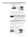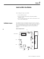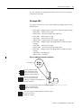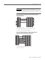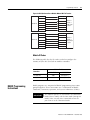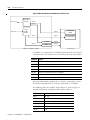
1
SLC 500 BASIC and
BASIC-T Modules
Catalog Numbers 1746-BAS and
1746-BAS-T
User Manual
Important User Information
Solid state equipment has operational characteristics differing from those of
electromechanical equipment. Safety Guidelines for the Application,
Installation and Maintenance of Solid State Controls, publication SGI-1.1,
available from your local Rockwell Automation sales office or online at
http://www.literature.rockwellautomation.com), describes some important
differences between solid state equipment and hard-wired electromechanical
devices. Because of this difference, and also because of the wide variety of
uses for solid state equipment, all persons responsible for applying this
equipment must satisfy themselves that each intended application of this
equipment is acceptable.
In no event will Rockwell Automation, Inc. be responsible or liable for
indirect or consequential damages resulting from the use or application of
this equipment.
The examples and diagrams in this manual are included solely for illustrative
purposes. Because of the many variables and requirements associated with
any particular installation, Rockwell Automation, Inc. cannot assume
responsibility or liability for actual use based on the examples and diagrams.
No patent liability is assumed by Rockwell Automation, Inc. with respect to
use of information, circuits, equipment, or software described in this manual.
Reproduction of the contents of this manual, in whole or in part, without
written permission of Rockwell Automation, Inc. is prohibited.
Throughout this manual, when necessary we use notes to make you aware of
safety considerations.
WARNING
IMPORTANT
ATTENTION
Identifies information about practices or circumstances
that can cause an explosion in a hazardous environment,
which may lead to personal injury or death, property
damage, or economic loss.
Identifies information that is critical for successful
application and understanding of the product.
Identifies information about practices or circumstances
that can lead to personal injury or death, property
damage, or economic loss. Attentions help you:
• identify a hazard.
• avoid a hazard.
• recognize the consequence.
SHOCK HAZARD
Labels may be located on or inside the equipment (for
example, drive or motor) to alert people that dangerous
voltage may be present.
BURN HAZARD
Labels may be located on or inside the equipment (for
example, drive or motor) to alert people that surfaces may
be dangerous temperatures.
Summary of Changes
The information below summarizes the changes to this manual since
the last printing.
To help you find new and updated information in this release of the
manual, we have included change bars as shown to the right of this
paragraph.
For
See page
Updated list of related publications
P-2
Updated memory module location on circuit board
2-2
Availability of 1747-M3 and 1747-M4 memory modules
3-4
Updated battery location on circuit board
3-1, C-2
Revised JW1 jumper illustration
3-2
Revised JW2 jumper illustration
3-3
Revised JW3 jumper illustration
3-4
Revised JW4 jumper illustration
3-5
SLC, SLC 500, Allen-Bradley, and Rockwell Automation are trademarks of Rockwell Automation, Inc.
Trademarks not belonging to Rockwell Automation are property of their respective companies.
Publication 1746-UM004B-EN-P - December 2005
2
Summary of Changes
Notes:
Publication 1746-UM004B-EN-P - December 2005
Table of Contents
Preface
Who Should Use This Manual . . .
Purpose of This Manual. . . . . . . .
Related Documentation . . . . .
How to Use This Manual . . . . . . .
Terms and Abbreviations. . . . . . .
Conventions Used in This Manual
.
.
.
.
.
.
.
.
.
.
.
.
.
.
.
.
.
.
.
.
.
.
.
.
.
.
.
.
.
.
.
.
.
.
.
.
.
.
.
.
.
.
.
.
.
.
.
.
.
.
.
.
.
.
.
.
.
.
.
.
.
.
.
.
.
.
.
.
.
.
.
.
.
.
.
.
.
.
.
.
.
.
.
.
.
.
.
.
.
.
.
.
.
.
.
.
.
.
.
.
.
.
.
.
.
.
.
.
.
.
.
.
.
.
P-1
P-1
P-2
P-2
P-3
P-3
Overview . . . . . . . . . . . . . . . . . . . . . . . . . .
BASIC and BASIC-T Modules. . . . . . . . . . . .
Hardware Features. . . . . . . . . . . . . . . . .
Software Features. . . . . . . . . . . . . . . . . .
Module Communication Ports. . . . . . . . .
Module LED Indicators. . . . . . . . . . . . . .
BASIC Development Software (1747-PBASE)
Typical Configurations. . . . . . . . . . . . . . . . .
Module Integration . . . . . . . . . . . . . . . .
Module Programming Interface. . . . . . . .
Module Network Configurations . . . . . .
.
.
.
.
.
.
.
.
.
.
.
.
.
.
.
.
.
.
.
.
.
.
.
.
.
.
.
.
.
.
.
.
.
.
.
.
.
.
.
.
.
.
.
.
.
.
.
.
.
.
.
.
.
.
.
.
.
.
.
.
.
.
.
.
.
.
.
.
.
.
.
.
.
.
.
.
.
.
.
.
.
.
.
.
.
.
.
.
.
.
.
.
.
.
.
.
.
.
.
.
.
.
.
.
.
.
.
.
.
.
.
.
.
.
.
.
.
.
.
.
.
1-1
1-2
1-2
1-3
1-3
1-4
1-5
1-6
1-6
1-7
1-10
Memory Requirements for BASIC Programming . .
Optional Memory Module . . . . . . . . . . . . . . . . . .
Components Required for DH485 Communication
Alternate Connection . . . . . . . . . . . . . . . . . . .
1747-AIC Isolated Link Coupler . . . . . . . . . . .
1747-PIC Interface/Converter . . . . . . . . . . . . .
DH485 Cable Requirements . . . . . . . . . . . . . . . . .
Components Required for DF1 Communication . .
.
.
.
.
.
.
.
.
.
.
.
.
.
.
.
.
.
.
.
.
.
.
.
.
.
.
.
.
.
.
.
.
.
.
.
.
.
.
.
.
.
.
.
.
.
.
.
.
.
.
.
.
.
.
.
.
2-1
2-2
2-3
2-4
2-5
2-5
2-6
2-6
.
.
.
.
.
.
.
.
.
.
.
.
.
.
.
.
.
.
.
.
.
.
.
.
.
.
.
.
.
.
.
.
.
.
.
.
.
.
.
.
.
.
.
.
.
.
.
.
.
.
.
.
.
.
.
.
.
.
.
.
.
.
.
.
.
.
.
.
.
.
.
.
.
.
.
.
.
.
.
.
.
.
.
.
.
.
.
.
.
.
.
3-1
3-2
3-3
3-4
3-5
3-6
3-9
3-9
3-10
3-11
3-11
3-12
3-14
Chapter 1
Module and Development
Software Overview
Chapter 2
Component Selection
Chapter 3
Install and Wire Your Module
i
Set Module Jumpers . . . . . . . . . . . . . . . . .
Set Jumper JW1 . . . . . . . . . . . . . . . . . .
Set Jumper JW2 . . . . . . . . . . . . . . . . . .
Set Jumper JW3 . . . . . . . . . . . . . . . . . .
Set Jumper JW4 . . . . . . . . . . . . . . . . . .
Install Your module . . . . . . . . . . . . . . . . .
Wire Your Communication Ports . . . . . . . .
Wire to Ports PRT1 and PRT2 . . . . . . . . . .
Hardware Handshaking . . . . . . . . . . . .
DTE and DCE Overview. . . . . . . . . . . .
DTE - Data Terminal Equipment. . . . . .
DCE - Data Communication Equipment
Wire to Port DH485 . . . . . . . . . . . . . . .
.
.
.
.
.
.
.
.
.
.
.
.
.
.
.
.
.
.
.
.
.
.
.
.
.
.
.
.
.
.
.
.
.
.
.
.
.
.
.
.
.
.
.
.
.
.
.
.
.
.
.
.
.
.
.
.
.
.
.
.
.
.
.
.
.
Publication 1746-UM004B-EN-P - December 2005
ii
Table of Contents
Chapter 4
Programming Overview
Understand Module Memory Organization . . . . . . . . . . . . .
Allocate SLC memory for the Module . . . . . . . . . . . . . . . . .
Module ID Codes. . . . . . . . . . . . . . . . . . . . . . . . . . . . .
BASIC Programming Instructions . . . . . . . . . . . . . . . . . . . .
BASIC Commands . . . . . . . . . . . . . . . . . . . . . . . . . . . .
BASIC Statements. . . . . . . . . . . . . . . . . . . . . . . . . . . . .
BASIC Operators . . . . . . . . . . . . . . . . . . . . . . . . . . . . .
Create and Edit a BASIC Program . . . . . . . . . . . . . . . . . . .
Enter a BASIC Program Using an ASCII Terminal. . . . . .
Run a BASIC Program . . . . . . . . . . . . . . . . . . . . . . . . .
Stop a BASIC Program . . . . . . . . . . . . . . . . . . . . . . . . .
Edit a BASIC Program Line Through an ASCII Terminal .
Delete a BASIC Program Line . . . . . . . . . . . . . . . . . . . .
Renumber a BASIC Program. . . . . . . . . . . . . . . . . . . . .
Transfer Data . . . . . . . . . . . . . . . . . . . . . . . . . . . . . . . . . .
Transfer Data Between the SLC Processor and
Port PRT2 . . . . . . . . . . . . . . . . . . . . . . . . . . . . . . . . . .
Transfer Data Between the SLC Processor and
Port PRT1 . . . . . . . . . . . . . . . . . . . . . . . . . . . . . . . . . .
Transfer Data Between the SLC Processor and
Port DH485 . . . . . . . . . . . . . . . . . . . . . . . . . . . . . . . . .
Transfer Data Between the SLC Processor and the
Module . . . . . . . . . . . . . . . . . . . . . . . . . . . . . . . . . . . .
Status Information for the SLC Processor . . . . . . . . . . . .
SLC Fault Codes . . . . . . . . . . . . . . . . . . . . . . . . . . . . . . . .
4-1
4-2
4-3
4-3
4-4
4-5
4-6
4-8
4-8
4-10
4-11
4-11
4-13
4-13
4-14
4-14
4-16
4-17
4-19
4-19
4-21
Appendix A
Specifications
Module Hardware Specifications . . . . . . . . . . . . . . . . . . . . 1-1
1747-PBASE BASIC Development Software Specifications . . 1-3
Related Products . . . . . . . . . . . . . . . . . . . . . . . . . . . . . . . . 1-3
Appendix B
Worksheets
Publication 1746-UM004B-EN-P - December 2005
Module Configuration . . . . . . . . . . . . . . . . . . . . . .
What to Do Next . . . . . . . . . . . . . . . . . . . . . . .
Port PRT1 Configuration (Jumper JW1) . . . . . . . . .
What to Do Next . . . . . . . . . . . . . . . . . . . . . . .
Port PRT2 Configuration (Jumper JW2) . . . . . . . . .
What to Do Next . . . . . . . . . . . . . . . . . . . . . . .
Optional Memory Module Selection (Jumper JW3) .
What to Do Next . . . . . . . . . . . . . . . . . . . . . . .
Program Port and Protocol Selection (Jumper JW4)
What to Do Next . . . . . . . . . . . . . . . . . . . . . . .
.
.
.
.
.
.
.
.
.
.
.
.
.
.
.
.
.
.
.
.
.
.
.
.
.
.
.
.
.
.
.
.
.
.
.
.
.
.
.
.
.
.
.
.
.
.
.
.
.
.
.
.
.
.
.
.
.
.
.
.
B-1
B-2
B-2
B-2
B-3
B-3
B-4
B-4
B-5
B-5
Table of Contents
iii
Appendix C
Lithium Battery Replacement,
Handling, and Disposal
Battery Replacement .
Battery Handling . . . .
Storage . . . . . . . .
Transportation . . .
Battery Disposal . . . .
.
.
.
.
.
.
.
.
.
.
.
.
.
.
.
.
.
.
.
.
.
.
.
.
.
.
.
.
.
.
.
.
.
.
.
.
.
.
.
.
.
.
.
.
.
.
.
.
.
.
.
.
.
.
.
.
.
.
.
.
.
.
.
.
.
.
.
.
.
.
.
.
.
.
.
.
.
.
.
.
.
.
.
.
.
.
.
.
.
.
.
.
.
.
.
.
.
.
.
.
.
.
.
.
.
.
.
.
.
.
.
.
.
.
.
.
.
.
.
.
.
.
.
.
.
.
.
.
.
.
.
.
.
.
.
.
.
.
.
.
C-1
C-3
C-3
C-3
C-5
Index
Publication 1746-UM004B-EN-P - December 2005
iv
Table of Contents
Publication 1746-UM004B-EN-P - December 2005
Preface
Read this preface to familiarize yourself with the rest of the manual.
This preface covers the following topics.
•
•
•
•
•
Who Should Use This
Manual
Who should use this manual
The purpose of this manual
How to use this manual
Terms and abbreviations
Conventions used in this manual
Use this manual if you are responsible for designing, installing,
programming, or troubleshooting control systems that use SLC 500
programmable controllers.
You should have a basic understanding of electrical circuitry and
familiarity with relay logic. If you do not, obtain the proper training
before using this product.
Purpose of This Manual
This manual is a reference guide for the design and installation of the
SLC 500 BASIC and BASIC-T modules. It describes the procedures for
installing and using the modules.
Chapter
1
Title
Contents
Preface
Describes the purpose, background, and scope of this
manual. Also lists related publications.
1
Module and
Development
Software Overview
Explains the hardware and software features.
2
Component Selection
Explains and illustrates how to select memory modules,
network configurations, and modems for your
application.
3
Install and Wire your
Module
Provides installation procedures and wiring guidelines.
4
Programming
Overview
Provides information needed to program your module.
Appendix A
Specifications
Presents the modules’ specifications.
Appendix B
Worksheets
Describes how to set the module for proper functioning.
Appendix C
Lithium Battery
Replacement,
Handling, and
Disposal
Provides important information for the replacement,
handling, and disposal of lithium batteries.
Publication 1746-UM004B-EN-P - December 2005
2
Preface
Related Documentation
The following documents contain additional information regarding
Rockwell Automation products.
For
Read
Publication Number
A BASIC language reference manual that describes BASIC
commands, CALLS, and functions
BASIC Language Reference Manual
1746-RM001
A programming manual with detailed instructions on installing and
using BASIC development software to program the BASIC and
BASIC-T module.
BASIC Development Software
Programming Manual
1746-PM001
An overview of the SLC 500 family of products
SLC 500 System Overview
1747-SO001
A description of how to install and use a Modular SLC 500
processor
Modular Hardware Style Installation
and Operation Manual
1747-UM011
A reference manual that contains status file data and instruction
set information for SLC 500 controllers
SLC 500 Instruction Set Reference
Manual
1747-RM001
A description of how to install and use a module that acts as a
bridge between DH485 networks and devices requiring DF1
protocol.
DH485/RS-232C Interface Module
User’s Manual
1747-UM005
In-depth information on grounding and wiring Allen-Bradley
programmable controllers
Allen-Bradley Programmable
Controller Grounding and Wiring
Guidelines
1770-4.1
A glossary of industrial automation terms and abbreviations
Allen-Bradley Industrial Automation
Glossary
AG-7.1
An article on wire sizes and types for grounding electrical
equipment
National Electric Code
Published by the National
Fire Protection Association
of Boston, MA
If you would like a manual, you can:
• download a free electronic version from the internet at
www.literature.rockwellautomation.com.
• purchase a printed manual by contacting your local distributor
or Rockwell Automation representative.
How to Use This Manual
Publication 1746-UM004B-EN-P - December 2005
To use this manual effectively, use the worksheets provided in
Appendix B. The worksheets can help you document your application
and settings and also facilitate the flow of information to other
individuals in your organization for implementation.
Preface
Terms and Abbreviations
3
The following terms and abbreviations are specific to this product. For
a complete listing of Allen-Bradley terminology, refer to the
Allen-Bradley Industrial Automation Glossary, publication ICCG-7.1.
• Module - SLC 500 BASIC and BASIC-T modules (catalog
numbers 1746-BAS and 1746-BAS-T)
• BASIC development software - BASIC Development Software
(catalog number 1747-PBASE)
• DH485 - network communication protocol
• EPROM - Erasable Programmable Read Only Memory
• MTOP - system control value that holds the last valid memory
address
• RS-232/423 - serial communication interface
• RS-422 - differential communication interface
• RS-485 - network communication interface
• SLC 500 - SLC 500 fixed and modular controller
Conventions Used in This
Manual
The following conventions are used throughout this manual.
• Bulleted lists such as this one provide information, not
procedural steps.
• Numbered lists provide sequential steps or hierarchical
information.
• Bold type is used for emphasis.
• Text in this font indicates words or phrases you should type.
Publication 1746-UM004B-EN-P - December 2005
4
Preface
Publication 1746-UM004B-EN-P - December 2005
Chapter
1
Module and Development Software Overview
This chapter introduces you to the SLC 500 BASIC and BASIC-T
modules and the BASIC development software. After reading this
chapter you should be familiar with the:
•
•
•
•
•
Overview
module components and features.
BASIC development software features.
typical configurations of the module.
module hardware specifications.
module-related products.
The module and the development software provide the following
benefits.
•
•
•
•
•
•
•
•
•
•
Easy data collection from user devices
Integrated program debugging environment
Operator interface capabilities
Flexible program and data storage options
High-level math
Clock/calendar
High-level programming environment
Extensive online help system
Easy access to editor functions through user interface
Advanced text editor windows
TIP
1
The 1746-BAS-T module is a higher-speed version of
the 1746-BAS module with identical hardware
features. The modules can be interchanged, except
that the 1746-BAS-T module uses different (optional)
memory modules. Due to the high speed of the
1746-BAS-T module, existing programs written for
the 1746-BAS module may require adjustment for
identical operation using the faster 1746-BAS-T
module.
Publication 1746-UM004B-EN-P - December 2005
1-2
Module and Development Software Overview
BASIC and BASIC-T
Modules
The modules are single-slot modules that reside in a SLC 500 fixed or
modular controller chassis. Use the module as:
• a foreign device interface.
• an operator interface.
Figure 1.1 Module with Door Open
BASIC
BASIC-T
5
4
3
2
1
9
8
7
6
5
4
3
2
1
PR T1
5
4
3
2
1
9
8
7
6
PR T1
9
8
7
6
5
4
3
2
1
9
8
7
6
PR T2
PR T2
DH485
DH485
Hardware Features
The module provides the following hardware features.
• 24 KB of battery backed RAM for storage of user programs and
data
• Capacitive backup of RAM during battery change
• Socket for a standard 1747-M1, M2, M3, or M4 memory module
(1746-BAS module) for nonvolatile storage of user programs
• Socket for a 1771-DBMEM1 or -DBMEM2 memory module
(1746-BAS-T module) for nonvolatile storage of user programs
• Battery-backed, 24-hour clock/calendar
• Free-running clock with 5 ms resolution
• Two isolated 9-pin D-shell serial ports (PRT1 and PRT2) that
provide RS-232/423, RS-422, and RS-485 communication with
I/O devices
• One PRT2 port provides DF1 full-duplex or half-duplex slave
protocol for SCADA applications
• One RJ-45 port (DH485) that provides communication over the
DH485 network
• Multiple LED indicators for operator interface
• SLC 500 backplane interface
Publication 1746-UM004B-EN-P - December 2005
Module and Development Software Overview
1-3
Software Features
The module provides the following software features.
• BASIC programming with the Intel BASIC-52 language and
enhancements
• SLC 500 backplane data read and write support including image
table transfers and M0 and M1 file transfers
• Execution of programs from memory modules
• String manipulation support
• DH485 network support
• DF1 protocol support
• Full set of trigonometric function instructions
• Floating point calculations and conversion
• Extensive call libraries
Module Communication Ports
There are three communication ports on the front of the module. The
location, name, and pin numbers of these ports are listed on the
inside of the module door. They are:
• PRT1 - Used to interface the module with user devices. This port
is a serial port that accommodates RS-232/423, RS-422, and
RS-485 communication modes. Port PRT1 is capable of operating
full-duplex at 300, 600, 1200, 2400, 4800, 9600, and 19200 Kbps.
The default settings are 1200 Kbps, RS-232/423 communications.
• PRT2 - Used to interface the module with user devices or a
modem using DF1 protocol. This port is a serial port that
accommodates RS-232/423, RS-422, and RS-485 communication
modes. Port PRT2 is capable of operating full-duplex at 300, 600,
1200, 2400, 4800, 9600, and 19200 Kbps.
• DH485 - Used to interface the module with the DH485 network.
This port is not isolated and cannot directly drive the DH485
network. You must use a 1747-AIC link coupler to link port
DH485 with the DH485 network.
IMPORTANT
When DF1 protocol is selected on port PRT2, DH485
communications are disabled.
Publication 1746-UM004B-EN-P - December 2005
1-4
Module and Development Software Overview
Module LED Indicators
There are eight LED indicators on the front of the module. These LED
indicators are used for module diagnostics and operator interface.
Figure 1.2 Module LEDs
BASIC
ACT
485
FAULT
BA LOW
PR T1
LED1
PR T2
LED2
LED
Color
Status
Indication
ACT
Green
ON
The module is receiving power from the backplane and is
executing BASIC code.
Blinking
The module is in Command mode.
OFF
The module is not receiving power from the backplane. A
fault condition exists.
ON
Port DH485 on the module is active for communication.
OFF
Port DH485 on the module is not active for communication.
Blinking
Port PRT1 on the module is transmitting or receiving signals.
OFF
Port PRT1 on the module is not transmitting or receiving
signals.
Blinking
Port PRT2 on the module is transmitting or receiving signals.
OFF
Port PRT2 on the module is not transmitting or receiving
signals.
ON
A system problem was detected during background
diagnostics. Contact your local Allen-Bradley representative.
OFF
No system problems are detected during background
diagnostics.
ON
The voltage of the battery that backs up RAM is low. A new
battery is needed.
OFF
The voltage of the battery that backs up RAM is at an
acceptable level.
ON
User definable. LED activated through the user program.
OFF
User definable. LED deactivated through the user program.
ON
User definable. LED activated through the user program.
OFF
User definable. LED deactivated through the user program.
485
PRT1
PRT2
FAULT
BA LOW
LED1
LED2
Publication 1746-UM004B-EN-P - December 2005
Green
Green
Green
Red
Red
Amber
Amber
Module and Development Software Overview
BASIC Development
Software (1747-PBASE)
1-5
The BASIC development software provides the user with a structured
and efficient means to create BASIC programs for the module. This
software is loaded into a an MS-DOS compatible personal computer. It
uses the personal computer to facilitate editing, compiling
(translating), uploading, and downloading of BASIC programs.
The BASIC development software has a menu-driven, window-type
environment that offers:
•
•
•
•
•
•
•
•
•
•
•
•
•
•
•
•
•
•
pull-down menus to access all editor functions.
function key access to frequently used functions.
multiple window editing.
cut and paste support between windows.
search and replace support.
search between files support.
built-in calculator that can paste results into your program.
ASCII look-up table.
line draw editor to create operator interface images without
having to enter ASCII characters.
keystroke macros.
undo and redo functions.
extensive help messages for each menu, menu option, and for
keywords embedded in the menu text.
capability to create user-defined macro libraries.
sophisticated debug tools including watch windows, single-step
operation, and go to cursor breakpoint operation.
syntax checked translations to native BASIC to reduce debug
time.
BASIC translator that steps through the BASIC program and
identifies errors.
ASCII terminal mode.
hex file transfer support.
The development software enables you to program the module from a
personal computer connected to either the module’s DH485 or PRT1
ports. The software allows direct access to the module through
terminal emulation over an RS-232/423 or DH485 network.
Refer to the BASIC Development Software Programming Manual,
publication 1746-PM001, for additional information on the software.
Publication 1746-UM004B-EN-P - December 2005
1-6
Module and Development Software Overview
Typical Configurations
The typical configuration of the SLC system that incorporates your
BASIC or BASIC-T module depends on whether the module is:
• integrated with a SLC 500 fixed or modular controller.
• programmed directly with an ASCII terminal or programmed
using a personal computer with the BASIC development
software, 1747-PBASE.
• communicating with a DH485 network or with an external
source through a modem using DF1 protocol.
Module Integration
The module is a single-slot module that is inserted into a slot in the
expansion chassis of your SLC 500 fixed controller or an open slot in
the 1746 I/O chassis of your SLC 500 modular controller. The module
may be inserted in any slot of the 1746 I/O chassis except the first slot
of the first chassis, which is reserved for the SLC modular processor.
Typical SLC fixed and modular configurations are shown in the
following figures.
Publication 1746-UM004B-EN-P - December 2005
Module and Development Software Overview
1-7
Figure 1.3 Typical Configurations
SLC 500 Fixed Controller
Power Supply
Slot
Filler
BASIC
or
BASIC-T
Module
SLC 500 Input BASIC Output
Modular Module
or
Module
Processor
BASIC-T
Module
Module Programming Interface
Your module can be programmed using an ASCII terminal with ASCII
terminal emulation software. You can also use a personal computer
with the BASIC development software (catalog number 1747-PBASE).
Use an ASCII terminal to enter a BASIC program one line at a time to
the module. Use a personal computer with the BASIC development
software to create a BASIC program that is then downloaded to your
module. Typical programming interface configurations include:
• ASCII terminal interface - Figure 1.4.
• BASIC development software interface (RS-232) - Figure 1.5.
• BASIC development software interface (DH485) - Figure 1.6.
Publication 1746-UM004B-EN-P - December 2005
1-8
Module and Development Software Overview
ASCII Terminal Interface
Use an ASCII terminal to enter a BASIC program one line at a time to
your module through port PRT1. The ASCII terminal connected to the
module must be an industrial terminal, workstation, or personal
computer (without the BASIC development software) that
communicates in alphanumeric mode. An ASCII terminal can also be
used to display charts or graphs generated by the BASIC program.
Figure 1.4 shows a typical ASCII terminal interface.
Figure 1.4 Module ASCII Terminal Interface
Null Modem
Cable
ASCII Terminal or Personal
Computer Running ASCII
Terminal Emulation Software
SLC 500 Controller with BASIC or BASIC-T Module
In this configuration, the RS232 port on the back of your industrial
terminal or personal computer is connected to port PRT1 on your
module. Port PRT1 must be configured as the program port.
See Chapter 3 for additional information on port configuration.
BASIC Development Software Interface (RS232)
Use a personal computer with the BASIC development software
(PBASE) to create a BASIC program that is then downloaded to your
module. PBASE provides an efficient means to edit, compile
(translate), upload, and download BASIC programs. Refer to the
BASIC Development Software Programming Manual, publication
1746-PM001, for additional information on this software.
Publication 1746-UM004B-EN-P - December 2005
Module and Development Software Overview
1-9
Figure 1.5 BASIC Development Software Interface (RS-232)
Null Modem
Cable
Personal Computer with BASIC
Development Software
SLC 500 Controller with BASIC or BASIC-T Module
In this configuration, the serial port on the personal computer is
connected to port PRT1 on the module. The personal computer
communicates with the module through terminal emulation over an
RS-232 interface. Port PRT1 must be configured as the program port.
See Chapter 3 for additional information on port configuration.
IMPORTANT
When using the BASIC development software to
interface with the RS-232 port of the module, PBASE
must be configured for RS-232 communication
through the configuration and terminal selection
menus. Refer to the BASIC Development Software
Programming Manual, publication 1746-PM001, for
additional information.
BASIC Development Software Interface (DH485)
In this configuration, the serial port on the personal computer
interfaced with port DH485 on the module through a 1747-PIC
interface/converter. Port DH485 must be configured as the program
port with DH485 protocol.
See Chapter 3 for additional information on port configuration.
Figure 1.6 BASIC Development software Interface (DH485)
Interface/Converter
RS-232 to RS-485
Catalog Number 1747-PIC
SLC 500 Controller
with BASIC or
BASIC-T Module
ASCII Terminal or Personal
Computer Running ASCII
Terminal Emulation Software
Publication 1746-UM004B-EN-P - December 2005
1-10
Module and Development Software Overview
The 1747-PIC interface/converter converts the RS-232 signals from the
personal computer RS-232 serial port to RS-485 format.
IMPORTANT
When using the BASIC development software to
interface with port DH485 of the module, PBASE
must be configured for DH485 communication
through the configuration and terminal selection
menus. Refer to the BASIC Development Software
Programming Manual, publication 1746-PM001, for
additional information.
Module Network Configurations
Your module may communicate with a DH485 network or it can
communicate with a remote device through a modem using the DF1
protocol. When DF1 protocol is used on PRT2, port DH485 is
disabled.
Typical communication configurations are shown in the following
figures.
• DH485 network configurations - Figure 1.7 and Figure 1.8
• DF1 protocol configuration - Figure 1.8
ATTENTION
Do not place the module on an active DH485
network until the node address and communication
rate of the module are configured. Refer to the
BASIC Language Reference Manual, publication
1746-RM001, for additional information on setting the
module node address and communication rate.
Figure 1.7 shows the module interfaced with a DH485 network
through a 1747-AIC isolated link coupler.
The link coupler also provides an interface to the DH485 network for
a personal computer with the BASIC Development Software.
Publication 1746-UM004B-EN-P - December 2005
Module and Development Software Overview
1-11
Figure 1.7 DH485 Network Configuration
SLC 500
Controller
1747-C11 Cable
DH485
Communication
Cable
(Belden #9842)
SLC 500 Controller
with BASIC or
BASIC-T Module
1747-C11 Cable
Personal Computer with BASIC
Development Software
1747-C10 Cable
Interface/Converter
RS-232 to RS-485
Catalog Number 1747-PIC
The 1747-PIC interface/converter converts the RS-232 signals from the
personal computer RS-232 serial port to RS-485 format. The 1747-AIC
link coupler links the converted signals with the DH485 network and
port DH485 on the module. Port DH485 must be configured as the
program port in order to communicate with PBASE software via the
DH485 network.
See Chapter 3 for additional information on port configuration.
IMPORTANT
Each module requires a link coupler port to interface
it with the DH485 network.
When using the BASIC development software to
interface with the module, the BASIC development
software must be configured for DH485
communication through the configuration and
terminal selection menus. Refer to the BASIC
Development Software Programming Manual,
publication 1746-PM001, for additional information.
Publication 1746-UM004B-EN-P - December 2005
1-12
Module and Development Software Overview
Figure 1.8 shows the module using DF1 to control communications
with a modem.
In this configuration, the module is interfaced with a DH485 network
through a peer-to-peer communication interface with full-duplex, DF1
protocol.
Figure 1.8 Full-duplex, DF1 Protocol Configuration
SLC 500
Controller with
BASIC or
BASIC-T Module
Modem
Modem
DH485 Communication
Cable
(Belden 9842)
SLC 500
Controller
with 1747-KE
Module(1)
Link Coupler
1747-AIC
1747-C13 Cable
1747-C11 Cable
Link Coupler
1747-AIC
Personal Computer with BASIC
Development Software
Interface/Converter
RS-232 to RS-485
Catalog Number
1747-PIC
SLC 500
Controller
1747-C11 Cable
(1) The 1747-KE module can be replaced by the 1770-KF3 DH485 communication interface module. The KF3 is a standalone version of the KE module.
The modems in this configuration may be dial-up. If the modems are
dial-up, the BASIC program may initiate dial-up and then switch port
PRT2 to DF1 protocol when connection is made to the 1747-KE
DH485 communication interface module. Port PRT2 on your module
must be configured as having DF1 protocol.
See Chapter 3 for additional information on port configuration.
The 1747-C13 cable acts only as a communication link and does not
carry 24V dc power. The 1747-C10 or 1747-C11 cable carries 24V dc
Publication 1746-UM004B-EN-P - December 2005
Module and Development Software Overview
1-13
power from the processor to the link coupler. (The 1747-C10 cable
and 1747-C11 cable are interchangeable.)
IMPORTANT
By configuring JW4 for DF1 communication on
PRT2, DH485 communications are disabled.
Publication 1746-UM004B-EN-P - December 2005
1-14
Module and Development Software Overview
Publication 1746-UM004B-EN-P - December 2005
Chapter
2
Component Selection
After reading this chapter, you should understand the:
• module memory requirements for BASIC programming and be
able to select the memory modules necessary for your
application.
• concepts of connecting your module to the DH485 network and
be able to select the components necessary for your application.
• concepts of connecting a modem to the module and be able to
select the necessary components for your application.
Memory Requirements for
BASIC Programming
The module uses the following types of memory modules during
BASIC programming.
• A 32 KB battery backed RAM of which 24 KB is reserved to store
BASIC programs and protected variables
• An optional 8 or 32 KB memory module to store BASIC
programs
IMPORTANT
1
Maximum user program storage space is 56 KB.
Battery backed RAM provides 24 KB and the
optional memory module provides up to 32 KB.
Publication 1746-UM004B-EN-P - December 2005
2-2
Component Selection
Optional Memory Module
The optional memory module provides nonvolatile storage of user
BASIC programs and port configuration. The socket that holds the
optional memory module is located on the module’s mother board as
shown in Figure 2.1.
Figure 2.1 Optional Memory Module Socket Location
CAT
FRN
SER
SLC 500
BASIC MODULE
SERIAL NO.
Memory Module Socket
54 3 2 1
CONFIG
9 87 6
54 3 2 1
DF1
9 87 6
DH485
ATTENTION
Do not expose the module to surfaces or other areas
that may typically hold an electrostatic charge.
Electrostatic charges can alter or destroy memory.
You may use any of the following memory module options with your
module.
•
•
•
•
Publication 1746-UM004B-EN-P - December 2005
1747-M1, 8 KB EEPROM (1746-BAS module only)
1747-M2, 32 KB EEPROM (1746-BAS module only)
1771-DBMEM1, 8 KB EEPROM (1746-BAS-T module only)
1771-DBMEM2, 32 KB EEPROM (1746-BAS-T module only)
Component Selection
2-3
Your module can program the 1747-M1, 1747-M2, 1771-DBMEM1, and
1771-DBMEM2 EEPROM optional memory modules. Jumper JW3 is
used to redirect the module circuitry for the different memory module
options.
Refer to Chapter 3 of this manual for additional information on jumper
JW3.
IMPORTANT
The module can program and erase EEPROM
memory modules. However, it cannot program or
erase UVPROM memory modules.
The data format of the module EEPROM optional memory module is
hexadecimal. The BASIC development software provides a hex file
transfer option that can be used to upload and download hex files to
the module EEPROM. The primary use of hex file transfers is to
transfer the data from an EEPROM in one module to an EEPROM in
another module. Refer to the BASIC Development Software
Programming Manual, publication 1747-PM001, for additional
information on hex file transfers.
Components Required for
DH485 Communication
Your module and the BASIC development software can interface with
a DH485 network using a combination of the following components.
• 1747-AIC isolated link coupler
• 1747-PIC interface/converter
• 1747-KE DH485/RS-232C communication interface module
Figure 2.2 shows some of these components in typical DH485
network interfaces.
Publication 1746-UM004B-EN-P - December 2005
2-4
Component Selection
Figure 2.2 DH485 Network Interface
Link Coupler
1747-AIC
SLC 500
Controller
1747-C11 Cable
DH485
Communication Cable
(Belden 9842)
Link Coupler
1747-AIC
SLC 500
Controller with
BASIC or BASIC-T
Module
1747-C11 Cable
Link Coupler
1747-AIC
Personal Computer with BASIC
Development Software
Interface/Converter
(1747-PBASE)
RS-232 to RS-485 Catalog
Number 1747-PIC
1747-C10 Cable
Alternate Connection
The 1747-C13 cable is designed to connect the following SLC 500
products to each other.
•
•
•
•
1747-AIC isolated link coupler
A 1746-BAS or 1746-BAS-T BASIC module
Fixed controllers
Modular controllers
The following figure shows one application for the 1747-C13 cable.
Publication 1746-UM004B-EN-P - December 2005
Component Selection
2-5
Figure 2.3 1747-C13 Cable Connection
DH485 Communication
Cable (Belden 9842)
Link Coupler
1747-AIC
SLC 500
Controller with
BASIC or BASIC-T
Module
1747-C10 Cable
1747-C13 Cable
The 1747-C10 cable supplies
power to the 1747-AIC.
The 1747-C13 cable acts only as a communication link and does not
carry 24V dc power. The 24V dc can come from either the processor
or an outside power source. The 1747-C10 or 1747-C11 cable carries
24V dc power from the processor to the link coupler. (The 1747-C10
and 1747-C11 are interchangeable.) A cable connected to the outside
power source carries 24V dc from the outside power source to the
link coupler.
The module and SLC 500 CPU act as two separate nodes on the
DH485 network.
Refer to the following sections for additional information on some of
the components shown in the previous figures.
1747-AIC Isolated Link Coupler
The 1747-AIC isolated link coupler lets you link modules to the
DH485 network.
Figure 2.2 and Figure 2.3 show a DH485 network with the module
and a personal computer linked to the network through a 1747-AIC
link coupler.
1747-PIC Interface/Converter
Use the 1747-PIC interface/converter to convert the RS-232 signals
from the personal computer’s serial port to RS-485 signal format.
Figure 2.2 shows the interface/converter integrating a personal
Publication 1746-UM004B-EN-P - December 2005
2-6
Component Selection
computer with the BASIC development software to the module across
a DH485 network.
IMPORTANT
DH485 Cable Requirements
When using the BASIC development software to
interface with the module through the 1747-PIC, the
BASIC development software must be configured for
DH485 communication through the configuration
and terminal selection menus. Refer to the BASIC
Development Software Programming Manual,
publication 1746-PM001, for additional information.
Use the 1747-C10 cable, 1747-C11 cable, or 1747-C13 cable to
interface port DH485 of the module with a 1747-AIC link coupler. Use
the DH485 communication cable, Belden #9842, to interface between
the link couplers on the DH485 network.
Refer to the SLC 500 Modular Style Programmable Controller User
Manual, publications 1747-UM011, for additional information on
DH485 cables.
Components Required for
DF1 Communication
Your module may use DF1 to communicate with external devices.
The DF1 driver is accessed through port PRT2. The module
communicates with the external devices using a:
• leased phone line.
• radio link.
• dial-up modem.
Refer to the following sections for additional information on these
components.
Publication 1746-UM004B-EN-P - December 2005
Component Selection
2-7
Figure 2.4 DF1 Communication Interface
SLC 500 Controller
with BASIC or
BASIC-T Module
Modem
Modem
DH485 Communication
Cable (Belden 9842)
Link Coupler
1747-AIC
1747-C11 Cable
Link Coupler
1747-AIC
Personal Computer with BASIC
Development Software
Interface/Converter
(1747-PBASE)
RS-232 to RS-485 Catalog
Number 1747-PIC
(1)
SLC 500 Controller
with 1747-KE
Module (1)
1747-C13 Cable
SLC 500
Controller
1747-C11 Cable
The 1747-KE module can be replaced by the 1770-KF3 DH485 communication interface module, a standalone version of the KE module.
Publication 1746-UM004B-EN-P - December 2005
2-8
Component Selection
Leased Phone Line
A leased phone line is a private, dedicated phone line. Leased phone
lines provide a phone link between modems that is available for
communication at all times. Typically, leased phone lines are used
when you have a high or constant transfer of communication between
the module and external devices.
Radio Link
A radio link provides a communication link when phone lines are
inaccessible or expensive to use. A radio link provides a
communications link between radio modems.
Dial-Up Modem
Dial-up or phone modems are modems capable of communicating
across standard phone lines. One dial-up modem initiates the
communication, while another modem receives the communication.
Publication 1746-UM004B-EN-P - December 2005
Chapter
3
Install and Wire Your Module
After reading this chapter, you should:
• set the module’s jumpers.
• install your module into your SLC 500 fixed or modular
controller system.
• wire the mating connectors of the cables used to interface user
devices to the module ports.
Set Module Jumpers
The module has four sets of jumpers that you need to set. Jumpers
JW1 and JW2 configure ports PRT1 and PRT2. Jumper JW3 configures
the type of optional memory module. Jumper JW4 configures the
program port. The following figure shows the location of these
jumpers.
Figure 3.1 Jumper Locations
JW1
CAT
FRN
SER
SLC 500
BASIC MODULE
SERIAL NO.
Memory Module
54 3 2 1
CONFIG
9 87 6
54 3 2 1
DF1
9 87 6
JW3
JW4
DH485
Battery
1
JW2
Publication 1746-UM004B-EN-P - December 2005
3-2
Install and Wire Your Module
ATTENTION
Do not expose the module to surfaces or other areas
that may typically hold an electrostatic charge.
Electrostatic charges can alter or destroy memory.
Set Jumper JW1
Use jumper JW1 to select one of the following configurations for port
PRT1.
• RS-232/423
• RS-422
• RS-485
Figure 3.2 JW1 Pin Assignments and Settings
Pin Assignments
2 4 6 8 10
1 3 5 7 9
RS-422
RS-485
RS-232/-423 (shipped configuration)
ATTENTION
Publication 1746-UM004B-EN-P - December 2005
All other jumper settings for JW1 are illegal and may
cause damage to the module.
Install and Wire Your Module
3-3
Use the worksheet in Appendix B to document the selected jumper
setting of jumper JW1. Documenting your selection provides others
with information necessary to integrate the module with their SLC 500
fixed or modular controllers.
Set Jumper JW2
Use jumper JW2 to select one of the following configurations for port
PRT2.
• RS-232/423
• RS-422
• RS-485
Figure 3.3 JW2 Pin Assignments and Settings
Pin Assignments
RS-232/-423 (shipped configuration)
9 7 5 3 1
10 8 6 4 2
RS-485
RS-422
ATTENTION
All other jumper settings for JW2 are illegal and may
cause damage to the module.
Use the worksheet in Appendix B to document the selected jumper
setting of jumper JW2. Documenting your selection provides others
with information necessary to integrate the module with their SLC 500
fixed or modular controllers.
Publication 1746-UM004B-EN-P - December 2005
3-4
Install and Wire Your Module
Set Jumper JW3
Use jumper JW3 to configure the memory module socket for one of
the following optional memory modules.
•
•
•
•
•
•
1747-M1, 8 KB EEPROM (1746-BAS module only)
1747-M2, 32 KB EEPROM (1746-BAS module only)
1747-M3, 8 KB UVPROM (1746-BAS module only)
1747-M4, 32 KB UVPROM (1746-BAS module only)
1771-DBMEM1, 8 KB EEPROM (1746-BAS-T module only)
1771-DBMEM2, 32 KB EEPROM (1746-BAS-T module only)
Figure 3.4 JW3 Pin Assignments and Settings
Pin Assignments
2 4
6
1 3 5
1747-M1 EEPROM (1746-BAS module only)
1747-M2 EEPROM (1746-BAS module only)
1747-M3 UVPROM (1746-BAS module only)
1771-DBMEM1 EEPROM (1746-BAS-T module only)
1771-DBMEM2 EEPROM (1746-BAS-T module only)
(shipped configuration)
1747-M4 UVPROM (1746-BAS module only)
The 1747-M3 and 1747-M4 memory modules are no longer available
for sale from Rockwell Automation. Existing 1747-M3 and 1747-M4
memory modules are compatible with the 1746-BAS module and
1746-BAS-T module.
ATTENTION
All other jumper settings for JW3 are illegal and may
cause damage to the module.
Documenting your selection provides others with information
necessary to integrate the module with their SLC 500 fixed or modular
controllers.
Publication 1746-UM004B-EN-P - December 2005
Install and Wire Your Module
3-5
Use the worksheet in Appendix B to document the selected jumper
setting of jumper JW3.
Set Jumper JW4
Use jumper JW4 to select one of the following configurations for the
module ports.
• PRT1 Port – Program port with default communication settings
PRT2 Port – ASCII interface port
DH485 Port – Runtime DH485 operation only
• PRT1 Port – ASCII interface port
PRT2 Port – ASCII interface port
DH485 Port – Program port with DH485 protocol
• PRT1 Port – Program port with programmed communication
settings
PRT2 Port – ASCII interface port
DH485 Port – Runtime DH485 operation only
• PRT1 Port – Program port with programmed communication
settings
PRT2 Port – DF1 protocol
DH485 Port – Disabled
Figure 3.5 JW4 Pin Assignments and Settings
2 4 6
Pin Assignments
1 3 5
PRT1 Port = Program port with
default communication settings
PRT2 Port = ASCII interface port
DH485 Port = Runtime DH485 only
PRT1 Port = ASCII interface port
PRT2 Port = ASCII interface port
DH485 Port = Program port with DH485 protocol
(shipped configuration)
PRT1 Port = Program port with programmed communication settings
PRT2 Port = ASCII interface port
DH485 Port = Runtime DH485 only
PRT1 Port = Program port with programmed communication settings
PRT2 Port = DF1 protocol
DH485 Port = Disabled
Publication 1746-UM004B-EN-P - December 2005
3-6
Install and Wire Your Module
IMPORTANT
ATTENTION
IMPORTANT
The first setting shown in Figure 3.5 is the default
configuration. When the jumper is set in this
position, the module always powers up in Command
mode at 1200 KB, no parity, 8 data bits, and 1 stop
bit.
All other jumper settings for JW4 are illegal and may
cause damage to the module.
When DF1 protocol is selected for port PRT2, port
DH485 is not available for DH485 programming or
runtime operation.
DF1 communication must be enabled through the
BASIC program.
Use the worksheet in Appendix B to document the selected jumper
setting of jumper JW4.
Documenting your selection provides others with information
necessary to integrate the module with their SLC 500 fixed or modular
controllers.
Install Your module
Once you have unpacked and set the jumpers on your module, you
are ready to install it in your:
• SLC 500 fixed controller expansion chassis.
• SLC 500 modular controller 1746 I/O chassis.
Your BASIC module or BASIC-T module may be installed in any open
slot of an SLC 500 1746 I/O chassis except the first slot of the first
chassis. The first slot is reserved for the processor or adapter module.
Publication 1746-UM004B-EN-P - December 2005
Install and Wire Your Module
3-7
The BASIC module or BASIC-T module can also be installed in an SLC
fixed controller expansion chassis.
ATTENTION
Never install, remove, or wire any module while
power is applied. Also, do not expose the modules
to surfaces or other areas that may typically hold an
electrostatic discharge.
Electrostatic discharge can damage integrated circuits
or semiconductors if you touch backplane connector
pins.
If the equipment is not installed and used as
described in the SLC 500 Modular Hardware Style
User Manual, publication 1747-UM011, the protection
provided by the equipment may be impaired.
1. Turn off power to the chassis where you will insert the module.
2. Align the circuit board of the module with the card guide of a
slot (except slot 0) in the 1746 chassis.
Figure 3.6 Module Location in the Chassis
Module Release
Card Guide
3. Slide the module in until the top and bottom retainer clips are
secured.
Publication 1746-UM004B-EN-P - December 2005
3-8
Install and Wire Your Module
Figure 3.7 Installation in a SLC 500 I/O Chassis
SLC 500 Processor
ATTENTION
Publication 1746-UM004B-EN-P - December 2005
Never install, remove, or wire any module with
power applied to the chassis.
Install and Wire Your Module
Wire Your Communication
Ports
3-9
The locations of the module’s communication ports, PRT1, PRT2, and
DH485, are shown in Figure 3.8.
Figure 3.8 Communication Ports
BASIC
BASIC-T
5
4
3
2
1
9
8
7
6
5
4
3
2
1
PR T1
5
4
3
2
1
Wire to Ports PRT1 and
PRT2
9
8
7
6
PR T1
9
8
7
6
5
4
3
2
1
9
8
7
6
PR T2
PR T2
DH485
DH485
Ports PRT1 and PRT2 can communicate to user devices through
RS-232/423, RS-422, and RS-485 communication modes. Set jumpers
JW1 and JW2 to reflect the communication mode you desire.
The table on page 3-10 lists the pin assignments for ports PRT1 and
PRT2.
Refer to the MODE command in the BASIC Language Reference
Manual, publication 1746-RM001, for the default programming port
configuration information.
IMPORTANT
When default communications are selected via JW4,
the module defaults to the Command mode when
power is cycled. Refer to page 3-5 of this manual for
the default communication settings.
Use these pin assignments to wire the mating connector of the cable
used to interface a user device to port PRT1. The sockets of this
connector must be wired to correspond to the selected
communication mode.
Publication 1746-UM004B-EN-P - December 2005
3-10
Install and Wire Your Module
Pin
RS-232/423
RS-422
RS-485
IBM AT Standard
RS-232 Signals
1
Note 1
422 TXD -
TRXD -
DCD or CD
2
RXD
422 RXD -
(3)
RXD
3
TXD
(2)
(2)
TXD
4
DTR
(2)
(2)
DTR
5
COMMON
COMMON
COMMON
COMMON
6
DSR
422 RXD +
(3)
DSR
7
RTS
(2)
(2)
RTS
8
CTS
(2)
(2)
CTS
9
(1)
422 TXD +
TRXD +
RI
(1)
In RS-423 mode, these pins are still connected to their RS-422 loads. Do not use these pins in RS-423 mode.
(2)
In RS-422 and RS-485 modes these pins are connected to their RS-423 drivers and receivers. Do not use these
pins in either RS-422 or RS-485 mode.
(3)
In RS-485 mode, these pins are still connected to their RS-422 receivers. Do not use these pins in RS-485 mode.
Wiring diagrams for the RS-232/423 communication mode are shown
starting on page 3-12.
Hardware Handshaking
The module uses the following rules when hardware handshaking is
enabled. The module:
• does not transmit until CTS becomes active.
• examines DSR following the receipt of a character. If the DSR is
active, the character is placed in the input queue. If DSR is
inactive, the character is assumed to be noise and is discarded.
Publication 1746-UM004B-EN-P - December 2005
Install and Wire Your Module
3-11
DTE and DCE Overview
IMPORTANT
You need to know whether the device connecting to
the module has a DTE or DCE interface.
Figure 3.9 through Figure 3.13 are provided to help
you make the appropriate connection.
DTE - Data Terminal Equipment
The module’s serial ports are configured as 9-pin Data Terminal
Equipment (DTE), as are most terminals or computer ports.
DTE 9 Pinout
Pin #
Signal Description
Signal from
DTE
Perspective
DTE 25 Pinout
Pin #
1
NC-No Connection
(for BASIC module only)
Input
8
2
RXD-Received Data
Input
3
3
TXD-Transmitted Data
Output
2
4
DTR-Data Terminal Ready
Output
20
5
Com-Signal Common
Shared
7
6
DSR-Data Set Ready
Input
6
7
RTS-Request to Send
Output
4
8
CTS-Clear to Send
Input
5
9
NC-No Connection
(for BASIC module only)
Input
22
Signal Description
CD-Carrier Detect
RI-Ring Indicator
Publication 1746-UM004B-EN-P - December 2005
3-12
Install and Wire Your Module
DCE - Data Communication Equipment
Devices such as modems are Data Communication Equipment (DCE).
The pinouts on these terminals are defined for ease of interfacing with
DTE equipment.
DCE 9 Pinout
Pin #
Signal from DCE
Perspective
Signal Description
Pin #
1
CD-Carrier Detect
Output
8
2
RXD-Received Data
Output
3
3
TXD-Transmitted Data
Input
2
4
DTR-Data Terminal Ready
Input
20
5
Com-Signal Common
Shared
7
6
DSR-Data Set Ready
Output
6
7
RTS-Request to Send
Input
4
8
CTS-Clear to Send
Output
5
9
RI-Ring Indicator
Output
22
IMPORTANT
All signal directions listed in the previous two tables
are valid. For example, TXD, Transmitted Data, is a
DTE output but is also a DCE input. The signal
description is the same for both the DTE and DCE
but the direction of the signal (perspective) has
changed based on whether you have a DTE or DCE
device.
Figure 3.9 RS-232/423 Wiring Diagram - Module to a Modem (Hardware
Handshaking Enabled)
Publication 1746-UM004B-EN-P - December 2005
DCE 25
Pinout
Basic DTE
DCE
9-pin
25-pin
1
N.C.
CD
2
RXD
RXD
3
TXD
TXD
1
2
3
4
5
6
7
8
9
8
3
2
20
7
6
4
5
22
4
DTR
DTR
5
COM
COM
6
DSR
DSR
7
8
RTS
CTS
RTS
CTS
9
N.C.
RI
Install and Wire Your Module
IMPORTANT
3-13
For DCE devices other than modems, connect the
DSR of the module with the DSR of the device. The
CD signal of the device (other than a modem) is not
used.
Figure 3.10 RS-232/423 Wiring Diagram - Module to DTE Device (Hardware
Handshaking Disabled)
Basic DTE
(2)
(2)
DTE
DCD (3)
1
N.C.
2
RXD
TXD
3
TXD
RSD
4
DTR
DSR
5
COM
COM
6
DSR
DTR
7
8
RTS
CTS
CTS
RTS
9
N.C.
GND(1)
9-pin 25-pin
1
3
2
6
5
4
8
7
8
2
3
6
7
20
5
4
1
(2)
(2)
(1)
Connect to the shield of the cable.
(2)
Jumpers are only needed if you cannot disable the hardware handshaking on the port.
(3)
This is a N.C. for the 1747-KE, 1746-BAS or 1746-BAS-T module.
Figure 3.11 RS-232/423 Wiring Diagram - Module to Printer (Hardware
Handshaking Enabled, Standard Printer Adapter Cable)(1)
Basic DTE
1 N.C.
2
3
4
5
6
RXD
TXD
DTR
COM
DSR
7
8
9
RTS
CTS
N.C.
DTE
CD
TXD
RXD
DSR
COM
DTR
CTS
RTS
RI
GND(2)
9-pin 25-pin
1
8
3
2
6
2
3
6
5
4
8
7
20
5
7
9
4
22
1
(1) The 1747-CP3 cable works in this application.
(2) Connect to the shield of the cable.
Publication 1746-UM004B-EN-P - December 2005
3-14
Install and Wire Your Module
Figure 3.12 RS-422 Wiring Diagram
Basic
1
TXD
2
RXD
RXD
TXD
3
4
5
COM
6
RXD+
COM
TXD+
TXD+
RXD+
7
8
9
Figure 3.13 RS-485 Wiring Diagram
Basic
1 TRXD-
TRXD-
2
3
4
5
COM
COM
6
7
8
9 TRXD+
TRXD+
Wire to Port DH485
Port DH485 can communicate to user devices through the DH485
communication mode. Use a 1747-C10 cable or 1747-C13 cable to
connect the module to a link coupler interfaced with the DH485
network.
Publication 1746-UM004B-EN-P - December 2005
Chapter
4
Programming Overview
This chapter provides an overview of the information needed to
program your module. After reading this chapter, you should be
familiar with:
•
•
•
•
module memory organization.
SLC memory allocation for your module.
BASIC programming instructions.
entering, running, and editing a BASIC program from an ASCII
terminal.
• interfacing the module with other devices.
Understand Module
Memory Organization
All data transferred to the module from the SLC 500 CPU must be
routed through the module input buffer. The following table lists the
addresses of the module input buffer.
Address
Definition
0...39
Data transferred from the DH485 common interface file.
40...99
Reserved
100...163
Data transferred from the CPU M0 file.
164...199
Reserved
200...207
Data transferred from the CPU output image table.
All data transferred from the module to the SLC 500 CPU must be
routed through the module output buffer. The following table lists the
addresses of the module output buffer.
1
Address
Definition
0...39
Data transferred to the DH485 common interface file.
40...99
Reserved
100...163
Data transferred to the CPU M1 file.
164...199
Reserved
200...207
Data transferred to the CPU input image table.
Publication 1746-UM004B-EN-P - December 2005
4-2
Programming Overview
Allocate SLC memory for
the Module
Your SLC 500 fixed or modular controller communicates to the
module through the SLC backplane interface. The backplane interface
transfers data from the CPU input and output image tables to the
module input and output buffers as shown in Figure 4.1.
For more information regarding the transfer of data between the SLC
controller and the module, refer to page 4-16 of this manual and to
the BASIC Language Reference Manual, publication 1747-RM001.
Figure 4.1 SLC 500 to Module Data Transfer
CPU Output
Image Table
CPU Input
Image Table
(1)
Word 0
Word 200
Word 1
Word 2
Word 201
Word 202
Word 3
Word 203
Word 4
Word 204
Word 5
Word 205
Word 6
Word 206
Word 7
Word 207
Word 0
Word 1
Word 2
Word 200(1)
Word 201
Word 202
Word 3
Word 203
Word 4
Word 204
Word 5
Word 205
Word 6
Word 206
Word 7
Word 207
BASIC or
BASIC-T
Module Input
Buffer
BASIC or
BASIC-T
Module Output
Buffer
Word 200 is predefined. You cannot write to word 200 of the BASIC output buffer.
In addition to transferring image table data, the SLC 5/02 controller
and above modular processor may transfer an additional 64 words of
input or output data to the module. Figure 4.2 shows the transfer of
M0 and M1 files between the SLC 5/02 processor, and higher, and the
module.
For more information on M0 and M1 files, refer to the SLC 500
Instruction Set Reference Manual, publication 1747-RM001.
Publication 1746-UM004B-EN-P - December 2005
Programming Overview
4-3
Figure 4.2 SLC 5/02 Controller to Module M0 and M1 File Transfer
Word 0
Word 100
Word 1
.
Word 101
.
.
.
.
.
Word 62
Word 162
Word 63
Word 163
Word 0
Word 100
Word 1
.
Word 101
.
.
.
.
.
Word 62
Word 162
Word 63
Word 163
CPU M0 File
CPU M1 File
BASIC or
BASIC-T
Module Input
Buffer
BASIC or
BASIC-T
Module Output
Buffer
Module ID Codes
The following table lists the ID codes needed to configure the
memory of your SLC 500 fixed or modular controller.
Controller
BASIC Programming
Instructions
Module ID Code
1746-BAS
1746-BAS-T
SLC 500, 5/01
3506
3523 (Class 1)
SLC 5/02 and higher
13106
13123 (Class 4)
BASIC programs are composed of BASIC programming instructions
grouped together. These instructions are a combination of BASIC
commands, statements, operators, and system subroutines (CALLs).
IMPORTANT
The module operates in two modes: the Command
mode (Direct mode) and the Run mode (Interpreter
mode). You can only enter commands when the
processor is in the Command mode.
Publication 1746-UM004B-EN-P - December 2005
4-4
Programming Overview
BASIC Commands
BASIC commands are programming instructions that are executed
during the Command mode except for CONTROL-C. CONTROL-C
takes you from Run mode to Command mode. Typically these
commands are used to perform some type of program maintenance.
The following table lists the BASIC programming commands.
Command
Function
Examples
CONT
CONTinue program execution after a STOP
statement or CONTROL-C command.
CONT
CONTROL-C
Stop current program execution in Run mode and
return module to Command mode.
[CTRL-C]
CONTROL S
Interrupt a LIST command.
[CTRL-S]
CONTROL Q
Restart a LIST command after a CONTROL S
command.
[CTRL-Q]
DISABLING
CONTROL-C
Disable the CONTROL-C break function. CALL 18
disables the CONTROL-C break function. CALL 19
re-enables the CONTROL-C break function.
CALL 18 (disable)
CALL 19 (re-enable)
ERASE
Erase the program stored in ROM.
ERASE
LIST
LIST current program or indicated lines of program
to the console device.
LIST, LIST 10-50
LIST#
LIST current program or indicated lines of program
to the device connected to port PRT1.
LIST#, LIST#50
LIST@
LIST current program or indicated lines of program
to the device connected to port PRT2.
LIST@, LIST@50
MODE
Set up port parameters.
MODE(DH485,19200)
NEW
Erase the program stored in RAM.
NEW
NULL
Count the number of null characters the module
outputs after a carriage return.
NULL, NULL4
PROG
Program the EEPROM module with the current
program.
PROG
PROG1
Program the EEPROM module with port information
for all three ports and store MTOP information.
PROG1
PROG2
Execute the first program stored in EEPROM when
the module is turned on.
PROG2
RAM
Select the current program from RAM.
RAM
ROM
Select the current program from EEPROM.
ROM, ROM3
RUN
Execute the currently selected program.
RUN
XFER
Transfer a program from EEPROM to RAM, then
select RAM mode.
XFER
Publication 1746-UM004B-EN-P - December 2005
Programming Overview
4-5
Refer to the BASIC Language Reference Manual, publication
1747-RM001, for additional information on these commands.
BASIC Statements
BASIC statements are programming instructions that are executed
during Run mode. Typically these statements are used to control
program execution. The following table lists the BASIC programming
statements.
Statement
Function
Examples
CLEAR
CLEAR variables, interrupts, and strings.
CLEAR
CLEAR (S&I)
CLEAR stacks and interrupts.
CLEARS, CLEARI
CLOCK (1&0)
Enable and disable free running clock.
CLOCK1, CLOCK0
DATA
Read information with the DATA statement.
DATA 100
DIM
Allocate memory for arrayed variables.
DIM A(20)
DO-WHILE
Set up loop for WHILE.
DO - WHILE
DO-UNTIL
Set up loop for UNTIL.
DO - UNTIL
END
Terminate program execution.
END
FOR-TO-STEP
Set up FOR-NEXT loop.
FOR A = 1 TO 5
GOSUB
Execute subroutine.
GOSUB 1000
GOTO
GOTO program line number.
GOTO 500
IF-THEN-ELSE
Test for a condition.
IF A>B THEN A=0
INPUT
INPUT a string or variable.
INPUT A
LD@
Load top of stack from user specified location.
LD@ 1000H, LD@ A
LET
Assign a variable or string a value. (LET is optional.)
LET A=1
NEXT
Test FOR-NEXT loop condition.
NEXT A
ONERR
Perform conditional arithmetic ERROR handling.
ONERROR 10
ON-GOTO
Perform conditional GOTO.
ON A GOTO 5, 20
ON-GOSUB
Perform conditional GOSUB.
ON A GOSUB 6, 2
ONTIME
Generate an interrupt when TIME is equal to or
greater than the expression following ONTIME
statement.
ONTIME10, 1000
PH0.
PRINT HEX mode with zero suppression.
PH0. A
PH1.
PRINT HEX mode without zero suppression.
PH1. A
POP
POP argument stack to variables.
POP A, B, C
PRINT
PRINT variables, strings or literals.
PRINT A
PUSH
PUSH expressions on argument stack.
PUSH 10, A
READ
READ data in a DATA statement.
READ A
REM
Insert a remark statement in a program.
REM DONE
RESTORE
RESTORE READ pointer.
RESTORE
Publication 1746-UM004B-EN-P - December 2005
4-6
Programming Overview
Statement
Function
Examples
RETI
RETURN from interrupt.
RETI
RETURN
RETURN from subroutine.
RETURN
ST@
Store top of stack at user specified location.
ST@ 1000H, ST@ A
STOP
Break program execution.
STOP
STRING
Allocate memory for STRINGs.
STRING 50, 10
Refer to the BASIC Language Reference Manual, publication
1747-RM001, for additional information on these statements.
BASIC Operators
BASIC operators are programming instructions that are executed
during Run mode. Typically these operators perform a predefined
operation on either variables or constants. Operators require either
one or two operands. The following table lists the BASIC
programming operators.
Operator
Function
Examples
ABS ( )
Return the absolute value of expression.
ABS (-3)
()+()
Add expressions together.
1+1
ASC ( )
Return integer value of ASCII character.
ASC (3)
ATN ( )
Return arraignment of argument.
ATN (1)
CHR ( )
Convert numeric expression to ASCII value.
CHR (65)
COS ( )
Return the cosine of argument.
COS (0)
()/()
Divide first expression by second expression.
10/2
EOF
Test for empty input buffer.
IF (NOT(EOF))
EXP ( )
Raise number to power of argument.
EXP (10)
( ) ** ( )
Raise first expression by the power of the second
expression.
2**4
FREE
List available bytes in RAM.
FREE=
GET
Read console.
P. GET
INT ( )
Return integer portion of expression.
INT (3.2)
IP
Read/assign IP register.
IP=0
LEN
List amount of bytes in current program.
LEN
LOG ( )
Return the natural log of the argument.
LOG (10)
( ) .AND. ( )
Combine the first expression with the second expression
using .AND..
10.AND.5
Publication 1746-UM004B-EN-P - December 2005
Programming Overview
Operator
Function
Examples
( ) .OR. ( )
Combine the first expression with the second expression
using .OR..
2.OR.1
( ) .XOR. ( )
Combine the first expression with the second expression
using .XOR..
3.XOR.2
MTOP
Return last valid memory address.
PRINT MTOP
()*()
Multiply expressions together.
4*4
p
Store constant.
3.1415926
RND
Return a random number.
RND
SGN ( )
Return the sign of argument.
SGN (-5)
SIN ( )
Return the sine of argument.
SIN (3.14)
SQR ( )
Return the square root of the argument.
SQR (100)
()-()
Subtract one expression from another.
8-4
TAN ( )
Return the tangent of argument.
TAN (.707)
TCON
Read/assign TCON register.
TCON=10H
TIME
Read/assign the free running clock.
P. TIME
XBY ( )
Read/assign external data memory.
P. XBY (10)
()=()
Allow the first expression to equal the second expression. 10=10
()<()
Allow the first expression to be less than the second
expression.
9<10
( ) <= ( )
Allow the first expression to be less than or equal to the
second expression.
X<=10
()>()
Allow the first expression to be greater than the second
expression.
10>9
( ) >= ( )
Allow the first expression to be greater than or equal to
the second expression.
X>=10
( ) <> ( )
Allows the first expression to be unequal to the second
expression.
10<>9
4-7
Refer to the BASIC Language Reference Manual, publication
1747-RM001, for additional information on these statements.
Publication 1746-UM004B-EN-P - December 2005
4-8
Programming Overview
Create and Edit a BASIC
Program
Module execution is controlled through a BASIC program residing in
RAM or ROM. You have the option of creating and editing this
program.
• on a personal computer using the BASIC development software
and then downloading it to the module. BASIC development
software uses an MS-DOS compatible personal computer to
facilitate editing, compiling (translating), uploading, and
downloading BASIC programs. Refer to the BASIC Development
Software Programming Manual, publication 1747-PM001, for
additional information on the BASIC development software.
• entering the program one line at a time directly to the module
using an ASCII terminal. ASCII terminal programming must be
done one line at a time.
Enter a BASIC Program Using an ASCII Terminal
BASIC line numbers indicate the order in which the program lines are
stored in memory. They are also used as references when branching
and editing. Typically you start numbering BASIC programs with line
number 10 and increment by 10. This lets you add additional lines
later as you work on your program.
Since the computer runs the statements in numerical order, additional
lines need not appear in consecutive order on the screen. For
example, if you enter line 35 after line 40, the computer still runs line
35 after line 30 and before line 40. This technique saves you from
re-entering an entire program if you forget to include a line.
IMPORTANT
Reuse of an existing line number causes all of the
information referenced by the original line number
to be lost. Be careful when entering numbers in the
Command mode; you may accidentally erase some
program lines.
After the line number, there may be a combination of BASIC
commands, statements, operators, or CALLs. Depending on the logic
of your program, there may be more than one statement on a line. If
so, each statement must be separated by a colon (:).
To enter a BASIC program using an ASCII terminal:
1. Select the program port using JW4.
Publication 1746-UM004B-EN-P - December 2005
Programming Overview
4-9
2. Connect the ASCII terminal to the selected program port on the
module.
3. Verify that the console device is configured to communicate with
the module (protocol and communication settings).
4. Apply power to your system.
If there is no program in RAM, this appears on the ASCII terminal.
SLC 500 BASIC Module - Catalog Number 1746-BAS
Firmware release: 1.00
Allen-Bradley Company, Copyright 1991
All rights reserved
If there is a program in RAM and the module has been programmed to
execute from RAM, this program starts running. If you type [Ctrl-C]
this screen appears:
.
.
.
STOP - IN LINE XXX
IMPORTANT
The system prompt [>] indicates that the module is
in Command mode, and the module ACT indicator
light should be blinking.
Publication 1746-UM004B-EN-P - December 2005
4-10
Programming Overview
5. Enter a line of the BASIC program at the system prompt [>].
READY
>10 REM FIRST PROGRAM
>20 PRINT “HELLO WORLD”
A BASIC program line always begins with a line number and
must contain at least one character, but no more than 68
characters.
6. Press
[RETURN]
to end the program line.
Run a BASIC Program
After entering your BASIC program, you are ready to run it. To run a
BASIC program, type RUN at the system prompt [>].
READY
>RUN
HELLO WORLD
Publication 1746-UM004B-EN-P - December 2005
Programming Overview
4-11
Stop a BASIC Program
To stop a program that is running, press
IMPORTANT
[Ctrl–C].
If [Ctrl–C] is disabled, you cannot stop program
execution through a BASIC command. You must
have jumper JW4 set in the default position and cycle
power to stop program execution.
Edit a BASIC Program Line Through an ASCII Terminal
When the module is in Command mode, you can edit the BASIC
program that resides in RAM. Editing a BASIC program is done on a
line-by-line basis. To edit an existing line in the BASIC program, type
EDIT and the line number of the line to edit as shown on the following
screen:
READY
>EDIT 10
The BASIC program line specified by the Edit command is displayed
on the ASCII terminal. You can perform any of the following edit
operations.
•
•
•
•
•
Cursor right and left
Replace a character
Insert a character
Delete a character
Retype a line
The table on the next page lists the BASIC edit operations, their
functions, and keystrokes required to perform the edit operation.
Publication 1746-UM004B-EN-P - December 2005
4-12
Programming Overview
Operation
Use To
Key Strokes
Move
Provide right/left cursor control.
[Space bar] - moves the cursor
one space to the right.
[Backspace] - moves the cursor
one space to the left.
Replace
Replace the character at the current
cursor position.
Press the key that corresponds to the
character that will replace the
character at the current cursor
position.
Insert
Insert text at the current cursor
position.
Important: When you use the Insert
command, all text to the right of the
cursor disappears until you type the
second [Ctrl–A]. Total line length is
79 characters.
[Ctrl-A]
Delete
Delete the character at the cursor
position.
[Ctrl-D]
Exit
Exit the editor with or without saving
the changes.
[Ctrl-Q] - exits the editor and
Copy the current line of text and insert
it at the line following the current line.
The cursor is moved to the first
character on the new line.
[RETURN]
Retype
Publication 1746-UM004B-EN-P - December 2005
Important: You must type a second
[Ctrl-A] to terminate the Insert
operation.
replaces the old line with the edited
line.
[Ctrl-C] - exits the editor without
saving any changes made to the line.
Programming Overview
4-13
Delete a BASIC Program Line
When the module is in Command mode, you can delete an existing
line of the BASIC program. To delete an existing line of the BASIC
program, type the line number of the line to delete; then press
[RETURN] as shown on the following screen:
READY
>10
Renumber a BASIC Program
When the module is in Command mode, you can renumber the BASIC
program that resides in RAM. To renumber a BASIC program, you
must enter a REN command at the system prompt [>]. The table at the
top of the next page lists the commands, functions, and keystrokes
needed to renumber your BASIC program.
IMPORTANT
The REN command updates the destination of
GOSUB, GOTO, ON ERR, ONTIME, and ON GOTO
statements.
If the target line number does not exist, or if there is
insufficient memory to complete the task, no lines
are changed and the message RENUMBER ERROR appears
on the console screen.
Because the REN command uses the same RAM for
renumbering as it does for variable and program
storage, available RAM may be insufficient in large
programs. You should renumber your program
periodically during development instead of waiting
until it is completed.
Publication 1746-UM004B-EN-P - December 2005
4-14
Programming Overview
Command
Renumbers the Program Starting at
Key Strokes
Renumber
The beginning of the program. The new
line numbers begin at 10 and increment by
10.
[REN]
The beginning of the program. The new
line numbers begin at 10 and increment by
NUM.
[REN[NUM]]
The beginning of the program. The new
line numbers begin with NUM1 and
increment by NUM2.
[REN[NUM1],[NUM2]]
NUM2. The new line numbers begin with
NUM1 and increment by NUM3.
[REN[NUM1],[NUM2],[NUM3]
Transfer Data
You can transfer data, through the use of various commands, between
the SLC processor and:
•
•
•
•
port PRT2.
port PRT1.
port DH485.
the 1746-BAS or 1746-BAS-T module.
Transfer Data Between the SLC Processor and Port PRT2
Use port PRT2 to interface the module with external devices sending
ASCII code (bar code decoders and printers) or DF1 packets (PLC
controllers). The commands in the following table are used to transfer
data either to or from port PRT2.
Publication 1746-UM004B-EN-P - December 2005
Command
Purpose
PRINT#
Prints a string or variable to PRT2.
INPUT#
Inputs a string or variable from PRT2.
INPL#
Inputs a string or variable from PRT2.
INPS#
Inputs a string or variable from PRT2.
GET#
Reads a console input device connected to PRT2.
CALL 22
Transfers data from PRT1 or PRT2 to the SLC I/O or M files.
CALL 23
Transfers data from the SLC I/O or M files to PRT1 or PRT2.
Programming Overview
Command
Purpose
CALL 118
Allows unsolicited writes from a remote SLC or PLC node.
CALL 122
Reads a PLC data file and transfers it to the SLC I/O or M files.
CALL 123
Transfers data from the SLC I/O or M files to a remote PLC.
4-15
Figure 4.3 Data Flow Between the SLC Processor and Port PRT2 of the Module
PRINT#
CALL 123
PRT2 OUTPUT QUEUE
CALL 23
Port PRT2
CALL 22
CALL 122
256 bytes
CALL 118
INPUT#
INPL#
INPS#
GET#
SLC Processor
256 bytes
PRT2 INPUT QUEUE
1746-BAS or 1746-BAS-T Module
In addition, the commands in the following table provide status of and
control over the data transfer between the SLC processor and port
PRT2 of the module.
Command
Purpose
MODE
Sets the port parameters of PRT1, PRT2, and DH485.
CALL 16
Enables interrupt capability when a DF1 packet is received.
CALL 17
Disables the DF1 packet interrupt capability.
CALL 30
Sets the port parameters for PRT2.
CALL 31
Displays the current PRT2 port configuration on the program port terminal
screen.
CALL 35
Retrieves the current character in the 256 character input buffer of port PRT2.
CALL 36
Retrieves the number of characters in the input or output buffer of port PRT2.
CALL 37
Clears the peripheral port input and/or output buffers.
CALL 97
Enables the DTR signal for port PRT2.
CALL 98
Disables the DTR signal for port PRT2.
CALL 108
Enables DF1 driver communications. You must use this CALL in conjunction
with CALLs 16, 17, 118, 122, and 123.
CALL 110
Prints the complete output buffer with addresses, front pointer, and number of
characters in the buffer to the console device.
CALL 111
Prints the complete input buffer with addresses, front pointer, and number of
characters in the buffer to the console device.
CALL 113
Disables DF1 driver communications.
Publication 1746-UM004B-EN-P - December 2005
4-16
Programming Overview
Command
Purpose
CALL 114
Initiates DF1 packet transmission.
CALL 115
Checks DF1 packet transmission status.
CALL 117
Gets DF1 packet length.
CALL 119
Resets port parameters back to their default settings.
For more information regarding the use of these commands, refer to
the BASIC Language Reference Manual, publication 1747-RM001.
Transfer Data Between the SLC Processor and Port PRT1
Use port PRT1 to interface the module with external devices sending
ASCII code. The commands in the following table are used to transfer
data either to or from port PRT1.
Command
Purpose
PRINT@
Prints a string or variable to PRT1.
INPUT@
Inputs a string or variable from PRT1.
INPL@
Inputs a string or variable from PRT1.
INPS@
Inputs a string or variable from PRT1.
GET@
Reads a console input device connected to PRT1.
CALL 22
Transfers data from PRT1 or PRT2 to the SLC I/O or M files.
CALL 23
Transfers data from the SLC I/O or M files to PRT1 or PRT2.
Figure 4.4 Data Flow Between the SLC Processor and Port PRT1 of the Module
PRINT@
CALL 23
PRT1 OUTPUT QUEUE
PORT PRT1
CALL 22
SLC Processor
256 bytes
256 bytes
INPUT@
INPL@
INPS@
GET@
PRT1 INPUT QUEUE
1746-BAS or 1746-BAS-T Module
In addition, the commands in the following table provide status of and
control over the data transfer between the SLC processor and port
PRT1 of the module.
Publication 1746-UM004B-EN-P - December 2005
Programming Overview
4-17
Command
Purpose
MODE
Sets the port parameters of PRT1, PRT2, and DH485.
CALL 94
Displays the current port PRT1 configuration on the program port terminal
screen.
CALL 95
Retrieves the number of characters in the input or output buffer of port PRT1.
CALL 96
Clears port PRT1 input and output buffers.
CALL 103
Prints the complete output buffer with addresses, front pointer, and number
of characters in the buffer to the program port screen.
CALL 104
Prints the complete input buffer with addresses, front pointer, and number of
characters in the buffer to the program port screen.
CALL 105
Resets the port parameters of port PRT1 to their default setting.
For more information regarding the use of these commands, refer to
the BASIC Language Reference Manual, publication 1747-RM001.
Transfer Data Between the SLC Processor and Port DH485
Use port DH485 to interface the module with the DH485 network
(other SLC processors). The commands in the following table are used
to transfer data either to or from port DH485.
Command
Purpose
CALL 14
Converts 16-bit signed integer located in the BASIC input buffer to BASIC
floating-point.
CALL 15
Converts 16-bit unsigned integer located in the BASIC input buffer to BASIC
floating-point.
CALL 24
Converts BASIC floating point to a 16-bit signed integer and places the result
in the BASIC output buffer.
CALL 25
Converts BASIC floating point to a 16-bit binary number and places the result
in BASIC output buffer.
CALL 27
Transfers the data from a remote DH485 data file to the SLC processor.
CALL 28
Transfers the data from the SLC processor to a remote DH485 data file.
CALL 84
Transfers the data from the DH485 common interface file to words 0 through
39 of the module input buffer.
CALL 85
Transfers words 0...39 of the module output buffer to the DH485 common
interface file.
CALL 90
Transfers the data from a remote DH485 data file to words 0...39 of the
module input buffer.
Publication 1746-UM004B-EN-P - December 2005
4-18
Programming Overview
Command
Purpose
CALL 91
Transfers words 0...39 of the module output buffer to a remote DH485 data
file.
CALL 92
Transfers the data from a remote DH485 interface file to words 0...39 of the
module input buffer.
CALL 93
Transfers words 0...39 of the module output buffer to a remote DH485
interface file.
CALL 118
Allows unsolicited writes from a remote SLC or PLC node.
Figure 4.5 Data Flow Between the SLC processor and Port DH485 of the Module
PRINT
CALL 28
ASCII OUTPUT
QUEUE
CALL 27
CALL 118
SLC Processor
CALL 24/25
PORT DH485
ASCII INPUT
QUEUE
INPUT
CALL 14/15
256 bytes
256 bytes
BASIC INPUT
BUFFER
BASIC
OUTPUT
BUFFER
CALL 90/92
CALL 84
CALL 91/93
COMMON
INTERFACE INPUT
FILE
COMMON
INTERFACE
OUTPUT FILE
256 bytes
256 bytes
CALL 85
In addition, the commands in the following table provide status of the
data transfer between the SLC processor and port DH485 of the
module.
Command Purpose
MODE
Sets the port parameters of PRT1, PRT2, and DH485.
CALL 86
Checks the remote write status of the DH485 common interface file.
CALL 87
Checks the remote read status of the DH485 common interface file.
For more information regarding the use of these commands, refer to
the BASIC Language Reference Manual, publication 1747-RM001.
Publication 1746-UM004B-EN-P - December 2005
Programming Overview
4-19
Transfer Data Between the SLC Processor and the Module
Use the module to interface with the SLC processor. For example, the
module performs large mathematical calculations for the processor
that the SLC processor uses to execute an operation. The commands
in the following table are used to transfer data either to or from the
SLC processor.
Command Purpose
CALL 14
Converts 16-bit signed integer located in the BASIC input buffer to BASIC
floating-point.
CALL 15
Converts 16-bit unsigned integer located in the BASIC input buffer to BASIC
floating-point.
CALL 24
Converts BASIC floating point to a 16-bit signed integer and places the result in
the BASIC output buffer.
CALL 25
Converts BASIC floating point to its 16-bit binary representation.
CALL 53
Transfers the eight words in the CPU output image table to words 200...207 of the
module input buffer.
CALL 54
Transfers words 200...207 of the module output buffer to the CPU input image
table.
CALL 56
Transfers the words in the CPU M0 file to words 100...163 of the module input
buffer.
CALL 57
Transfers words 100...163 of the module output buffer to the CPU M1 file.
Status Information for the SLC Processor
Input image word 0 for the module slot contains two status bits. One
status bit informs the SLC processor of the mode the module is
presently in. The other status bit informs the SLC processor of the
battery status. These status bits are:
• I:e. 0/13 = 0 battery OK, 1 battery low
• I:e. 0/15 = 0 module in Run mode, 1 module in Command mode
Publication 1746-UM004B-EN-P - December 2005
4-20
Programming Overview
Figure 4.6 Data Flow Between the Module and SLC Processor
CALL 14/15
BASIC INPUT
BUFFER
CALL 53
CALL 56
CALL 24/25
BASIC
OUTPUT
BUFFER
SLC OUTPUT
IMAGE
16 bytes
16 bytes
CALL 54
SLC M0
CALL 57
SLC M1
SLC INPUT IMAGE
128 bytes
128 bytes
SLC Processor
1746-BAS or 1746-BAS-T Module
In addition, the commands in the following table provide status of and
control over the data transfer between the SLC processor and module.
Command Purpose
CALL 51
Checks if the CPU output image buffer was updated.
CALL 55
Checks if the CPU input image buffer was read by the processor.
CALL 58
Checks if the CPU M0 file was updated.
CALL 59
Checks if the CPU M1 file was read by the processor.
CALL 86
Checks if the DH485 interface file was updated.
CALL 87
Checks if the DH485 interface file was read by an external device.
CALL 120
Clears the module input and output buffers.
For more information regarding the use of these commands, refer to
the BASIC Language Reference Manual, publication 1747-RM001.
The following table lists module buffer addresses. Refer to page 4-1
for more information regarding module buffer addresses.
Publication 1746-UM004B-EN-P - December 2005
Address
BASIC Input/Output Buffer Address
M1:e.s
100...163
M0:e.s
100...163
I:e.s
200...207
O:e.s
200...207
CIF in
0...39
CIF out
0...39
Programming Overview
4-21
The SLC processor and module operate independently of each other.
The following CALLs allow the SLC processor and module to interrupt
each other.
SLC Fault Codes
CALL
Purpose
CALL 16
Enables interrupt capability when a DF1 packet is received.
CALL 17
Disables the DF1 packet interrupt capability.
CALL 20
Enables SLC processor interrupt capability.
CALL 21
Disables SLC processor interrupt capability.
CALL 26
Generates an interrupt to the SLC processor.
Fault codes are reported in word 6 of the SLC processor status file.
The format of the status word and applicable error codes are shown
below:
Figure 4.7 SLC Fault Code Placement
4-digit Hex Number
Slot Number
SLC
Fault
Code
57H
Fault Code
Description
Possible Cause
Recommended Action
Module has not
responded to a lock
shared memory command
within the required time
limit.
Module hardware problem.
Module internal stacks,
pointers (if XBY instructions
are used) are corrupted by the
user program.
Module hardware problem.
Module internal stacks,
pointers (if XBY instructions
are used) are corrupted by the
user program.
Cycle power to the
module to re-initialize
parameters and re-run
the program.
58H
Module generated a
generic fault.
59H
Module did not complete
a command within the
required time limit.
Verify that module is
configured correctly
(correct I/O and M files).
Cycle power to the
module to re-initialize
parameters and re-run
the program.
Module hardware problem.
Cycle power to the
module to re-initialize
Module internal stacks,
parameters and re-run
pointers (if XBY instructions
are used) are corrupted by the the program.
user program.
Publication 1746-UM004B-EN-P - December 2005
4-22
Programming Overview
SLC
Fault
Code
5AH
Description
Possible Cause
Recommended Action
Hardware interrupt
problem.
Module hardware problem.
Module internal stacks,
pointers (if XBY instructions
are used) are corrupted by the
user program.
Module is trying to be
configured using G files.
Wrong M0/M1 file size is
chosen.
Verify that the module
slot is enabled. Cycle
power to the module to
re-initialize parameters
and re-run the program.
5BH
G file configuration error.
5CH
M0/M1 file configuration
error.
5DH
Interrupt requested but
the processor will not
support the interrupt.
75H
Module watchdog
timeout.
90H
Module issued an
interrupt while the slot
was disabled.
Module has faulted while
slot was disabled.
91H
92H
Module I/O or ISR
configuration is incorrect.
93H
Processor did not
recognize the error code
from the Module.
SLC 500 fixed controller or
5/01 modular processor does
not support module
interrupts.
Module hardware problem.
Module internal stacks,
pointers (if XBY instructions
are used) are corrupted by the
user program.
Module is issuing an I/O
interrupt. CALL 26 causes this
interrupt.
Module hardware problem.
Module internal stacks,
pointers (if XBY instructions
are used) are corrupted by the
user program.
Module slot was configured
incorrectly in the SLC ladder
logic program.
Module hardware problem.
Module internal stacks,
pointers (if XBY instructions
are used) are corrupted by the
user program.
Verify the module is not
configured with G files.
Verify the module is
configured with M0 or
M1 files no larger than
64 words.
A 5/02 or higher
processor must be used
for interrupt capability.
Cycle power to the
module to re-initialize
parameters and re-run
the program.
Enable the slot before
using interrupts.
Cycle power to the
module to re-initialize
parameters and re-run
the program.
Verify the slot
configuration for the
module.
Cycle power to the
module to re-initialize
parameters and re-run
the program.
Application errors such as divide by zero error, syntax error, receipt of
a CONTROL-C, and execution of STOP or END statements cause the
module to return to the Command mode from Run mode. Use CALL
38 (EXPANDED ONERR) to jump to an interrupt routine instead of
returning to the Command mode.
Publication 1746-UM004B-EN-P - December 2005
Appendix
A
Specifications
Module Hardware
Specifications
The module hardware specifications are listed in the following tables.
Specification
Value
Power Supply Loading at
5V dc
0.150 A (module only)
Power Supply Loading at
24V dc
0.070 A (module only)
0.150 A (module with link coupler)
0.125 A (module with link coupler)(2)
Noise Immunity
NEMA Standard ICS 2-230
Vibration
Displacement: 0.015 in., peak-to-peak at 5...57 Hz
Acceleration: 2.5 g at 57...2000 Hz
1
Shock (operating)
30 g
Port Isolation(1)
Port PRT1
Port PRT2
Port PRT1 to Port PRT2
710V dc for 1 minute (backplane to port)
710V dc for 1 minute (backplane to port)
710V dc for 1 minute (port PRT1 to port PRT2)
Ambient Temperature
Rating
Operating: 0...+60 °C (+32...+140 °F)
Storage: -40...+85 °C (-40...+185 °F)
Humidity
5...95% without condensation
Clock/Calendar Accuracy
±1 minute/month at 25 °C (77 °F)
+0, -6 minute/month at 60 °C (140 °F)
(1)
Port DH485 is not isolated.
(2)
If a Hand-held Terminal, Data Table Access Module, or interface converter is connected to the link coupler,
the additional backplane power draw of these components must be added to the 0.125 listed in the table
above. This only applies when the module is connected to the network via the link coupler and 1747-C10
cable or 1747-C11 cable. This does not apply when the 1747-C13 cable is used.
Certification
Value
Agency Certification
c-UL-us listed
Class I, Groups A, B, C or D, Division 2
CE compliant for all applicable directives
C-Tick marked for all applicable acts
Publication 1746-UM004B-EN-P - December 2005
A-2
Specifications
IMPORTANT
If a Hand-held Terminal, Data Table Access Module,
or interface converter is connected to the link
coupler, the additional backplane power draw of
these components must be added to the 0.125 A
listed in the table above. This only applies when the
module is connected to the network via the link
coupler and 1747-C10 cable or 1747-C11 cable. This
does not apply when the 1747-C13 cable is used.
Component
Operating Voltage
Current Requirement
Hand-held Terminal
24V dc
0.105 A
Data Table Access Module
24V dc
0.104 A
Interface Converter
24V dc
0.060 A
IMPORTANT
IMPORTANT
The BASIC module receives its power from the SLC
backplane. The power consumption of the module
must be taken into consideration when planning
your SLC 500 system. Refer to the documentation
supplied with your SLC 500 fixed or modular
controller for additional information on power
supplies and current requirements.
Port DH485 is not isolated.
Communication
Rate (Kbps)
RS-232
RS-423
RS-422
RS-485
300
15 (50)
1230 (4000)
1230 (4000)
1230 (4000)
600
15 (50)
920 (3000)
1230 (4000)
1230 (4000)
1200
15 (50)
770 (2500)
1230 (4000)
1230 (4000)
4800
15 (50)
245 (800)
1230 (4000)
1230 (4000)
9600
15 (50)
120 (400)
1230 (4000)
1230 (4000)
19200
15 (50)
60 (200)
1230 (4000)
1230 (4000)
IMPORTANT
Publication 1746-UM004B-EN-P - December 2005
Distance Allowed in m (ft)
Use the RS-423 jumper settings when communicating
in RS-232 mode.
Specifications
1747-PBASE BASIC
Development Software
Specifications
A-3
The BASIC development software must be loaded into a personal
computer to operate. This personal computer must conform to the
following specifications.
• IBM PC/AT compatible computer with display and keyboard
• DOS version 3.1 to 6.22
• 640 KB of RAM memory
• 1 floppy disk drive (3 1/2 in. or 5 1/4 in.)
• Hard disk with 2 MB free disk space
• One RS-232 compatible serial port
Refer to the BASIC Development Software Programming Manual,
publication 1747-PM001, for additional information.
Related Products
The following table lists the products related to the module.
Product
Catalog Number
8 KB EEPROM Memory Module for 1746-BAS module
1747-M1
32 KB EEPROM Memory Module for 1746-BAS module
1747-M2
8 KB EEPROM Memory Module for 1746-BAS-T module
1771-DBMEM1
32 KB EEPROM Memory Module for 1746-BAS-T module
1771-DBMEM2
BASIC Development Software
1747-PBASE
Communication Cable, 1828.8 mm (72 in.) length, interchangeable with
C-11 cable)
1747-C10
Communication Cable, 304.8 mm (12 in.) length, interchangeable with
C-10 cable)
1747-C11
Communication Cable, 914.4 mm (36 in.) length, different from C-10 and
C-11 cables)
1747-C13
Interface/Converter (RS-232 to RS-485)
1747-PIC
Link Coupler
1747-AIC
SLC 5/01 controller
1747-L511, -L514
SLC 5/02 controller
1747-L524
SLC 5/03 controller
1747-L531, -L532
SLC 5/04 controller
1747-L541, -L542,
-L543
SLC 5/05 controller
1747-L551, -L552,
-L553
Publication 1746-UM004B-EN-P - December 2005
A-4
Specifications
Publication 1746-UM004B-EN-P - December 2005
B
Appendix
Worksheets
This appendix contains important information you should be
concerned with when configuring the module. The information is
general in nature and supplements specific information contained in
earlier chapters of this manual.
Topics include worksheets for configuring:
• the BASIC or BASIC-T module.
• jumpers JW1-JW4.
Module Configuration
Specify the connection information by filling in the boxes in the figure
below.
Figure B.1 Module Configuration
BASIC
Connected Device: YES______ NO ______
Device Type: _______________________
Protocol: __________________________
Program Port: YES______ NO ______
Connected Device: YES______ NO ______
Device Type: _______________________
Protocol: _________________________
Connected Device: YES______ NO ______
Device Type: _______________________
Protocol: __________________________
Program Port: YES______ NO ______
IMPORTANT
1
5
4
3
2
1
9
8
7
6
PR T1
5
4
3
2
1
9
8
7
6
PR T2
DH485
When DF1 protocol is selected for port PRT2, the
DH485 port is not available for programming or
runtime operation.
Publication 1746-UM004B-EN-P - December 2005
B-2
Worksheets
What to Do Next
Give a copy of this worksheet to the hardware installer. Store this
worksheet with your application program for future reference.
Port PRT1 Configuration
(Jumper JW1)
See Figure 3.1 for the locations of the four jumpers.
See Figure 3.2 for jumper JW1 pin assignments and settings.
Specify the configuration of port PRT1 on your module by filling in
the table below.
Port
Configuration
Selection
Corresponding Jumper Position on JW1
PRT1
RS-232/423
Across pins 1 and 2, 3 and 4
RS-422
Across pins 5 and 6, 7 and 8
RS-485
Across pins 7 and 8, 9 and 10
What to Do Next
Give a copy of this worksheet to the hardware installer. Store this
worksheet with your application program for future reference.
Publication 1746-UM004B-EN-P - December 2005
Worksheets
Port PRT2 Configuration
(Jumper JW2)
B-3
See Figure 3.1 for the locations of the four jumpers.
See Figure 3.3 for jumper JW2 pin assignments and settings.
Specify the configuration of port PRT2 on your module by filling in
the table below.
Port
Configuration
Selection
Corresponding Jumper Position on
JW2
PRT2
RS-232/423
Across pins 1 and 2, 3 and 4
RS-422
Across pins 5 and 6, 7 and 8
RS-485
Across pins 7 and 8, 9 and 10
What to Do Next
Give a copy of this worksheet to the hardware installer. Store this
worksheet with your application program for future reference.
Publication 1746-UM004B-EN-P - December 2005
B-4
Worksheets
Optional Memory Module
Selection (Jumper JW3)
See Figure 3.1 for the locations of the four jumpers.
See Figure 3.4 for jumper JW3 pin assignments and settings.
Specify the optional memory module selection for the system by
filling in the table below.
Memory Module Option
Optional
Memory
Module
Selection
Corresponding Jumper
Position on JW3
1747-M1 8 KB EEPROM (1746-BAS module
only)
Across pins 1 and 3, 2 and 4
1747-M2 32 KB EEPROM (1746-BAS module
only)
Across pins 1 and 3, 2 and 4
1747-M3 8 KB UVPROM (1746-BAS module
only)
Across pins 1 and 3, 2 and 4
1747-M4 32 KB UVPROM (1746-BAS module
only)
Across pins 3 and 5, 4 and 6
1771-DBMEM1 8 KB EEPROM (1746-BAS-T
module only)
Across pins 1 and 3, 2 and 4
1771-DBMEM 32 KB EEPROM (1746-BAS-T
module only)
Across pins 1 and 3, 2 and 4
What to Do Next
Give a copy of this worksheet to the hardware installer. Store this
worksheet with your application program for future reference.
Publication 1746-UM004B-EN-P - December 2005
Worksheets
Program Port and Protocol
Selection (Jumper JW4)
B-5
See Figure 3.1 for the locations of the four jumpers.
See Figure 3.5 for jumper JW4 pin assignments and settings.
Specify the Program Port and its protocol by filling in the table below.
Selection Port
Program
Port?
Protocol
Corresponding Jumper
Position on JW4
PRT1
YES
Default Communication
Settings
PRT2
NO
ASCII Interface
DH485
NO
Runtime DH485
PRT1
NO
ASCII Interface
PRT2
NO
ASCII Interface
DH485
YES
DH485 Program Port
(non-isolated)
PRT1
YES
Programmed
Communication Settings
PRT2
NO
ASCII Interface
DH485
NO
Runtime DH485
PRT1
YES
Programmed
Communication Settings
PRT2
NO
DF1
DH485
NO
Disabled
Across pins 3 and 4, 5 and 6
Across pins 1 and 3, 2 and 4
Across pins 3 and 5, 4 and 6
Across pins 1 and 2, 3 and 4
What to Do Next
Give a copy of this worksheet to the hardware installer. Store this
worksheet with your application program for future reference.
Publication 1746-UM004B-EN-P - December 2005
B-6
Worksheets
Publication 1746-UM004B-EN-P - December 2005
Appendix
C
Lithium Battery Replacement, Handling, and
Disposal
This appendix contains important information you should know when
using lithium batteries.
Battery Replacement
Your module provides back-up power for RAM through a replaceable
lithium battery (catalog number 1747-BA). This battery provides
back-up for approximately five years. A BAT LOW indicator on the
front of the module alerts you when the battery voltage has fallen
below the replace battery threshold level.
To replace the lithium battery:
1. Remove power from the SLC 500 power supply.
ATTENTION
Do not remove the module from the SLC 500 chassis
until all power is removed from the SLC 500 power
supply.
2. Remove the module from the chassis by depressing the retainer
clips at both the top and bottom of the module and slide it out.
IMPORTANT
ATTENTION
1
If the top or bottom retainer clips are broken when
removing the module they can be easily replaced.
Pry the broken clip(s) off from the bottom with a
screwdriver, if necessary. Do not twist off. Snap in
the replacement clip. Order Catalog Number
1746-R15 (2 per package).
Do not expose the module to surfaces or other areas
that may typically hold an electrostatic charge.
Electrostatic charges can alter or destroy memory.
Publication 1746-UM004B-EN-P - December 2005
C-2
Lithium Battery Replacement, Handling, and Disposal
Figure C.1 Battery Location
CAT
FRN
SER
SLC 500
BASIC MODULE
SERIAL NO.
54 3 2 1
CONFIG
9 87 6
54 3 2 1
DF1
9 87 6
DH485
Red Wire
White Wire
Battery
3. Unplug the battery connector.
IMPORTANT
The module has a capacitor that provides 30 minutes
of battery back-up while the battery is disconnected.
Data in RAM is not lost if the battery is replaced
within 30 minutes.
4. Remove the battery from the retaining clips.
5. Insert a new battery into the battery retaining clips.
6. Plug the battery connector into the socket with the red lead wire
on top and the white lead wire on the bottom.
7. Re-insert the BASIC module into the SLC 500 chassis.
8. Restore power to the SLC 500 power supply module.
Publication 1746-UM004B-EN-P - December 2005
Lithium Battery Replacement, Handling, and Disposal
Battery Handling
C-3
The procedures listed below must be followed to be sure of proper
battery operation and reduce personnel hazards.
• Use battery only for intended operation
• Do not ship or dispose of cells except according to
recommended procedures
• Do not ship on passenger aircraft
ATTENTION
Do not charge the batteries. An explosion could
result or the cells could overheat causing burns.
Do not open, puncture, crush, or otherwise mutilate
the batteries. A possibility of an explosion exists and
toxic, corrosive, and flammable liquids would be
exposed.
Do not incinerate or expose the batteries to high
temperatures.
Do not attempt to solder batteries. An explosion
could result.
Do not short positive and negative terminals
together. Excessive heat can build up and cause
severe burns.
Storage
Store lithium batteries in a cool, dry environment, typically +20 to
+25 °C (+68 to +77 °F) with 40% to 60% humidity. Store the batteries
and a copy of the battery instruction sheet in the original container,
away from flammable materials.
Transportation
One or Two Batteries
Each battery contains 0.23 g of lithium. Therefore, up to two batteries
can be shipped together within the United States without restriction.
Regulations governing shipment to or within other countries may
differ.
Publication 1746-UM004B-EN-P - December 2005
C-4
Lithium Battery Replacement, Handling, and Disposal
Three or More Batteries
Procedures for the transportation of three or more batteries shipped
together within the United States are specified by the Department of
Transportation (DOT) in the Code of Federal Regulations, CRF49,
“Transportation”. An exemption to these regulations, DOT – E7052,
covers the transport of certain hazardous materials classified as
flammable solids. This exemption authorizes transport of lithium
batteries by motor vehicle, rail freight, cargo vessel, and cargo-only
aircraft, providing certain conditions are met. Transport by passenger
aircraft is not permitted.
A special provision of the DOT – E7052 (11th Rev., October 21, 1982,
par. 8-a) provides that:
Persons that receive cell and batteries covered by this exemption
may reship them pursuant to the provisions of 49 CFR 173.22a in
any of these packages authorized in this exemption including
those in which they were received.
The Code of Federal Regulations, 49 CRF 173.22a, relates to the use of
packaging authorized under exemptions. In part, it requires that you
must maintain a copy of the exemption at each facility where the
packaging is being used in connection with shipment under the
exemption.
Shipment of depleted batteries for disposal may be subject to specific
regulation of the countries involved or to regulations endorsed by
those countries, such as the IATA Restricted Articles Regulations of the
International Air Transport Association, Geneva, Switzerland.
Regulations for transportation of lithium batteries are periodically
revised.
Publication 1746-UM004B-EN-P - December 2005
Lithium Battery Replacement, Handling, and Disposal
Battery Disposal
C-5
The following procedures must be followed when disposing of
lithium batteries.
ATTENTION
Do not incinerate or dispose of lithium batteries in
general trash collection. Explosion or violent rupture
is possible. Batteries should be collected for disposal
in a manner to prevent against short circuiting,
compacting, or destruction of case integrity and
hermetic seal.
For disposal, batteries must be packaged and shipped in accordance
with the transportation regulations, to a proper disposal site. The U.S.
Department of Transportation authorizes shipment of “Lithium
batteries for disposal” by motor vehicle only in regulation 173.1015 of
CRF49 (effective January 5, 1983). For additional information contact:
U.S. Department of Transportation
Research and Special Programs Administration
400 Seventh Street, S.W.
Washington, D.C. 20590
Although the Environmental Protection Agency at this time has no
regulations specific to lithium batteries, the material contained may be
considered toxic, reactive, or corrosive. The person disposing of the
material is responsible for any hazards created in doing so. State and
local regulations may exist regarding the disposal of these materials.
Publication 1746-UM004B-EN-P - December 2005
C-6
Lithium Battery Replacement, Handling, and Disposal
Publication 1746-UM004B-EN-P - December 2005
Index
Numerics
1746-BAS BASIC Module 1-2, 2-4
1746-BAS-T BASIC-T Module 1-2, 2-4
1747-AIC Isolated Link Coupler 1-10,
2-3, 2-4, 2-5
1747-C10 Cable 1-13, 2-5, 2-6
1747-C11 Cable 1-10, 1-13, 2-5
1747-C13 Cable 1-13, 2-4
1747-KE DH-485/RS-232C Communication
Interface Module 2-3
1747-M1 8 KB EEPROM 2-2, 3-4
1747-M2 32 KB EEPROM 2-2, 3-4
1747-M3 8 KB UVPROM 3-4
1747-M4 32 KB UVPROM 3-4
1747-PBASE BASIC Development
Software 1-5
1747-PIC Interface/Converter 1-9, 1-11,
2-3, 2-5
1771-DBMEM1 8 KB EEPROM 2-2, 3-4
1771-DBMEM2 32 KB EEPROM 2-2, 3-4
A
abbreviations and terms P-3
ASCII terminal interface 1-8
B
BASIC commands 4-4
BASIC development software
overview 1-5
RS-232 interface 1-8
RS-485 interface 1-9
specifications 1-3
BASIC or BASIC-T module
ASCII terminal interface 1-8
BASIC development software interface
1-8, 1-9
communication ports 1-3
data transfer with SLC 4-2, 4-19
DF1 communication interface 2-6
DH-485 communication interface 2-3
hardware features 1-2
hardware specifications 1-1
installation and wiring 3-1
integration 1-6
LEDs 1-4
memory organization 4-1
network configurations 1-10
optional memory module 2-2
overview 1-1
programming 4-1
programming interface 1-7
related products 1-3
software features 1-3
typical configurations 1-6
battery back-up C-1
C
cables 2-4, 2-6
CALLs 4-14
communication cable DH485 2-6
communication ports
DH485 1-2, 1-3, 3-5, 3-14, 4-17
PRT1 1-2, 1-3, 3-2, 3-5, 3-9, 4-16
PRT2 1-2, 1-3, 3-3, 3-5, 3-9, 4-14,
B-3
component selection overview 2-1
components needed for DF1
communication
dial-up modem 2-6
leased phone line 2-6
radio link 2-6
components needed for DH485
communication
1747-AIC Isolated Link Coupler 2-3
1747-KE DH-485/RS-232C
Communication Interface
Module 2-3
1747-PIC Interface/Converter 2-3
configurations
typical 1-6
worksheets B-1
contents of manual P-1
creating and editing a BASIC program
4-8
D
data transfer between the SLC and the
module 4-2, 4-19
DCE 3-12
definitions P-3
deleting a program line 4-13
DF1
communication interface 2-6
components required for 2-6
dial-up modem 2-8
leased phone lines 2-8
radio links 2-8
DH485 communication cable 2-6
DH485 communication port 1-2, 1-3,
3-5, 3-14, 4-17
Publication 1746-UM004B-EN-P - December 2005
2
Index
DH485 network
cable requirements 2-6
interfacing with the module and
development software 1-3,
2-3
dial-up modem for DF1 communication
2-6
DTE 3-11
E
editing a program line 4-11
EEPROM 2-2, 3-4
entering a program 4-8
H
hardware features 1-2
hardware handshaking 3-10
I
input/output buffer address map 4-20
installation and wiring
communication ports 3-9
DH485 communication port 3-5, 3-14,
4-17
fixed controller expansion rack 3-6
modular controller rack 3-6
overview 3-1
PRT1 communication port 3-2, 3-5,
3-9, 4-16
leased phone lines for DF1
communication 2-6
LEDs 1-2, 1-4
link coupler 2-4
lithium battery
disposal C-5
handling C-3
replacement C-1
storage C-3
transportation C-3
M
M0/M1 file transfers 1-3, 4-2
manuals
related P-2
memory organization 4-1
memory requirements 1-2, 2-1
modem 2-8
module ID codes 4-3
module input buffer addresses 4-1
module integration
overview 1-6
with SLC 500 modular controller 3-6
with SLC fixed controller 1-6, 3-6
module output buffer addresses 4-1
module programming interface 1-7
N
network configurations 1-10
PRT2 communication port 3-3, 3-5,
3-9, 4-14, B-3
3-2, B-2
3-3, B-3
3-4, B-4
3-5, B-5
setting jumper JW1
setting jumper JW2
setting jumper JW3
setting jumper JW4
interrupt CALLs 4-21
J
jumper JW1 3-2
jumper JW1 worksheet
jumper JW2 3-3
jumper JW2 worksheet
jumper JW3 3-4
jumper JW3 worksheet
jumper JW4 3-5
jumper JW4 worksheet
L
Publication 1746-UM004B-EN-P - December 2005
B-2
B-3
B-4
B-5
O
optional memory modules
1747-M1 8 KB EEPROM 2-2, 3-4
1747-M2 32 KB EEPROM 2-2, 3-4
1747-M3 8 KB UVPROM 3-4
1747-M4 32 KB UVPROM 3-4
1771-DBMEM1 8 KB EEPROM 2-2, 3-4
1771-DBMEM2 32 KB EEPROM 2-2, 3-4
overview 2-2
worksheet B-4
overview 1-1
P
PBASE 1-5
ports
see communication ports 1-3
programming
commands 4-4
Index
creating and editing 4-8
data transfer between the SLC and BASIC
module 4-2, 4-19
deleting a program line 4-13
editing a program line 4-11
entering a program 4-8
instructions 4-3
memory requirements 2-1
module ID codes 4-3
module input buffer addresses 4-1
module output buffer addresses 4-1
operators 4-6
overview 4-1
renumbering a program 4-13
running a program 4-10
statements 4-5
stopping a program 4-11
programming instructions 4-3
programming operators 4-6
programming statements 4-5
PRT1 communication port 1-2, 1-3, 3-2,
3-5, 3-9, 4-16
PRT2 communication port 1-2, 1-3, 3-3,
3-5, 3-9, 4-14, B-3
publications
related P-2
3
fault codes 4-21
fixed controller 1-6, 3-6
SLC 500 modular controller 3-6
SLC fault codes 4-21
SLC processor
status information 4-19
software features 1-3
status bits
status information for the SLC processor
4-19
status information for the SLC processor
4-19
SLC processor 4-19
stopping a program 4-11
T
terms and abbreviations P-3
transferring data between SLC processor
and the module
overview 4-14
port DH485 4-17
port PRT1 4-16
port PRT2 4-14
SLC processor 4-19
transferring data overview 4-14
typical configurations 1-6
R
radio link for DF1 communication 2-6
related products 1-3
renumbering a program 4-13
RS-232 interface 1-8
RS-485 interface 1-9
running a program 4-10
S
setting jumper JW1 3-2
setting jumper JW2 3-3, B-3
setting jumper JW3 3-4, B-4
setting jumper JW4 3-5
SLC 500
backplane interface 1-3
U
UVPROM 3-4
W
wiring to DH485 communication port
3-5, 3-14
wiring to PRT1 communication port 3-2,
3-5, 3-9
wiring to PRT2 communication port 3-3,
3-5, 3-9, B-3
worksheets
BASIC module configuration B-1
optional memory module selection B-4
port PRT2 configuration B-3
Publication 1746-UM004B-EN-P - December 2005
Rockwell Automation
Support
Rockwell Automation provides technical information on the web to assist you
in using its products. At http://support.rockwellautomation.com, you can find
technical manuals, a knowledge base of FAQs, technical and application
notes, sample code and links to software service packs, and a MySupport
feature that you can customize to make the best use of these tools.
For an additional level of technical phone support for installation,
configuration and troubleshooting, we offer TechConnect Support programs.
For more information, contact your local distributor or Rockwell Automation
representative, or visit http://support.rockwellautomation.com.
Installation Assistance
If you experience a problem with a hardware module within the first 24
hours of installation, please review the information that's contained in this
manual. You can also contact a special Customer Support number for initial
help in getting your module up and running:
United States
1.440.646.3223
Monday – Friday, 8am – 5pm EST
Outside United
States
Please contact your local Rockwell Automation representative for any
technical support issues.
New Product Satisfaction Return
Rockwell tests all of its products to ensure that they are fully operational
when shipped from the manufacturing facility. However, if your product is
not functioning and needs to be returned:
United States
Contact your distributor. You must provide a Customer Support case
number (see phone number above to obtain one) to your distributor in
order to complete the return process.
Outside United
States
Please contact your local Rockwell Automation representative for
return procedure.
ö
Publication 1746-UM004B-EN-P - December 2005 5
Supersedes Publication 1746-UM004A-US-P - April 2000
Copyright © 2005 Rockwell Automation, Inc. All rights reserved. Printed in the U.S.A.