1
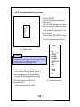
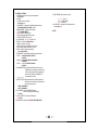
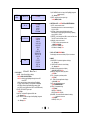
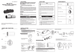
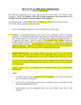
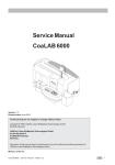
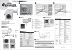
Marshall Electronics
CV360-CGB
2MP HDSDI / HDMI Broadcast Camera (GenLock in 1920x1080p)
User’s Manual
2014.08.20 VER.
- 1
-
CAUTION
Please read precautions before the using this product.
▶ This manual is created to prevent camera loss and to protect user safety.
▶ The following symbols explain the damage or loss if not used properly.
WARNING
Indicates that there may be cause
of injury or loss if user violates the
notice.
CAUTION
Indicates that there may be cause
of death or critical injury if the user
violates the notice.
- 2
-
Precautions
1. Moisture
Do not install the product in areas with high humidity or rain pene
tration. It may cause malfunction and fire if water enters into the
camera's internal compartments.
2. Repair
Do not modify or disassemble. There may be risk of electric shoc
k, etc. In case of a camera fault, please don’t fix it directly, pleas
e contact manufacturer.
3. Power
Do not use other Power Supply not specified by company. There
may be cause for electrical shock or damage to camera.
4. Conditions
Do not install this camera in extreme temperatures, such as too
hot or too cold areas.
(Recommended use temperature : -5 ℃ ~ 50 ℃)
5. Sun Light
If the camera lens is exposed to direct sun or strong light, dama
ge can occur to camera or camera componentsl.
6. Shock or Vibration
Be careful not to drop the camera or expose to strong shock.
7. Installation in unstable places
Do not install the camera on unstable mounts or fictures, tripods,
brackets, tables as it can cause people to get hurt or damage to
be done to camera product.
8. If the camera is not working properly
If the camera is not operating correctly (for example, strange noise, sme
ll or smoke), please stop using it immediately, remove power source, a
nd contact your local dealer.
9. Cleaning
Turn off the camera and remove from power source during cleaning and
use dry cloth to clean camera or lens components.
If material is hard to remove, please use furniture cleaner or unabrasiv
e material to clean camera housing .
When cleaning LENS, please use lens blower or lens cleaning tissue.
If you have further questions about cleaning please consult your local c
amera dealer or supplier.
10. Exposure to the light source
In case of abnormal light sources, Horizontal or Vertical lines may appe
ar in monitor. This 'smear‘ effect is a compensation feature of the semic
onductor device itself, not a breakdown. Please use recommended ligh
t sources.
11. How to request troubleshooting help or request a RMA repair
Please contact Marshall Electronics for repair in the following cases aft
er the camera is removed from the power source.
A. If the connector of the power supply is broken,
B. If you expose the camera to rain or water,
C. If liquid or material has been spilled into the camera,
D. If it is not turning on while following instructions of the camera setup
described in this document.
Control adjustments of the camera are not working properly.
(The camera to be operated in a manner not described in the
documentation there is a larger danger of damage.)
E. If the camera has been dropped and damaged
F. If there is a distinct change in performance
Damage of product caused by Natural disasters such
as lightning strike or inadvertent installation will be re
paired at MEI repair rates and labor cost.
- 3
-
Contents
1. Features
------------------------------------------------------------- 5
2. OSD operation
----------------------------------------------------- 6
3. Genlock Description
---------------------------------------------- 11
4. Precautions of Installment----------------------------------------- 12
Thank you for purchasing the CV360-CGB. If you want to get a better understanding of this products functio
ns and capabilities, please read the user manual carefully before using this product. Keep this User's Guide
for future reference. If a problem occurs during the use, please contact Marshall Electronics.
- 4
-
1. Features
♦ This product is a 1/3” CMOS 2.1 MegaPixel Full-HD Progressive Scan, high sensitivity color Broadcast camera for
all types of video production projects and applications
♦ Utilizing a 1/3" 2.1MegaPixel Panasonic C-MOS High Performance Sensor
♦ HD-SDI/3G-SDI/HDMI: 1920x1080p – 25, 29.97, 30, 50, 59.94, 60fps, 1920x1080i – 50, 59.94, 60fps, 1280x720p –
50, 59.94, 60fps
♦ SDI signal Standardization: SMPTE292M (SMPTE274M)
♦ High sensitivity: 0.1lux low luminance (F1.2, 50IRE AGC MAX, DSS 4X:0.01 Lux)
♦ GENLOCK Support SYNC mode in 1080p-50, 59.94, 60fps
1. GENLOCK SYNC Signal: Tri-Level 1.2Vp-p(75 Ω)
2. Camera to Camera link SYNC Mode
a) Master mode: Genlock SYNC Output
b) Slave mode: Genlock SYNC Input
c) Disable mode: Genlock Signal - No Input / No Output
♦ OSD control :
Automatic gain control, Electronic Level control or Auto level control, level of maximum accumulation level
adjustment, WDR, BLC, HLC, Genlock mode, Default title and camera ID settings, OSD arbitrary adjustments.
● White balance mode(WB) : AUTO / AUTOEXT / PRESET / MANUAL(R-Gain, B-Gain)
● Back light compensation : BLC / WDR
● High light Back light compensation : HLC
● Noise remove(DNR): OFF / LOW / MIDDLE / HIGH
● Accumulation mode(SENS-UP) : OFF / 2X / 3X / 4X / 8X / 16X / 32X
● Day & night setting(DAY &NIGHT) : AUTO / B/W / COLOR / EXTERN
● Privacy masking : BOX / POLYGON
● Motion detect : OFF / ON
● Zoom(D-ZOOM) : 1.0x~16.0x
● Analog video output: CVBS 1.0Vp-p , NTSC, PAL
● Digital Image Stabilizer function(DIS) : RANGE / FILTER / AUTO C
● GENLOCK Function : Disable / Master / Slave
● IMAGE RANGE : FULL / COMP / USER
- 5
-
2. OSD Menu manipulation explanation
<
MENU
IRIS
FOCUS ADJUST
EXPOSUER
BACKLIGHT
DAY & NIGHT
WHITE BAL AUTO
DNR
IMAGE
DIS
MOTION
SYSTEM
EXIT
2.2 Activate “OSD MENU”
a. Press “set button” to Move to the Menu setting
display on monitor.
b. Press “Up button” to move upper menu or “Down
button” to move bottom menu. Selected menu item is
illuminated in yellow color when on specific feature.
c. Press “right button” to increase data value “or “left
button” to decrease it.
d. Press right button in “OSD < MENU>” to move into
the sub menu bar right away. User can choose 1~12
menu. And vise versa when you press “left button.”
>
<
<2-1. OSD Menu Location >
☞ Caution
Press OSD Menu button on back of camera for 3 seconds, This will start OSD menu on screen.
Press “set button” again to move into the “SUB menu” in OSD "↲" menu.
Press the button for more than 3 seconds to activate “push menus”.
2.1 How to display On-Screen-Display (OSD) Menu
a. User can activate OSD menu by pressing “set button”. If
no other commands are given, OSD menu will disappear.
b. Activation of OSD Menu disappear without camera title.
If you don’t want to show camera title, please change inner
OSD in camera. (optional for use with RS-232
communication control.)
c. User can change camera title (ID) locations .
- 6
MENU
>
IRIS
FOCUS ADJUST
EXPOSUER
BACKLIGHT
DAY & NIGHT
WHITE BAL AUTO
DNR
IMAGE
DIS
MOTION
SYSTEM
EXIT
<2-2. Setting start menu display>
-
2.3 How to start “OSD SUB MENU”
SETUP
MENU
IRIS
FOCUS ADJUST
EXPOSUER ◀
BACKLIGHT
DAY & NIGHT ◀
1. IRIS : Which controls the amount of light entering for the camera
1) Electronic Level Control : Using the electronic Shutter
2) Auto Level Control: Using the Lens Shutter
< ELC/ALC >
ELC/ALC
ON/OFF
2. FOCUS ADJUST: Focus Lens be controlled focus by Automatic
< ON/OFF >
BRIGHTNESS
SUTTER
SENS-UP
AGC
3. EXPOSUER
1) BRIGHTNESS : Set the basic brightness of display
< 0 ~ 20 Steps, 10 >
2) SUTTER: Control shutter speed to adjust brightness.
< AUTO / MANUAL /FLICKER >
① AUTO : Auto Shutter speed mode
1] AUTO/ SUTTER (ELC)
< NORMAL/DEBLUR >
1> NORMAL: Auto Shutter mode in ELC
2> DEBLUR : Correct to Developing Attraction by Automatic
2] AUTO/ SUTTER (ALC)
< INDOOR/OUTDOOR/OUTDOOR2/DEBLUR >
1> INDOOR : It just iris without rolling effect in indoor
2> OUTDOOR : It is solution mode for low quality display
because of closed iris at outdoor.
3> OUTDOOR 2: It improve losing focus in strong sum beam
at “Outdoor”
4> DEBLUR : Correct to Developing Attraction by Automatic
② MANUAL : Control shutter Speed to adjust brightness
<SPEED (1/30(25), 1/60(50),1/120(100),
1/250,1/500,1/1000,1/1600,1/2500,
1/5000,1/7000,1/10000,1/30000) >
③ FLICKER : Correct to flashing on the screen
3) SENS-UP : Accumulation Mode
< OFF/2X/3X/4X /8X/16X/32X >
4) AGC : Full gain value setting (AGC)
< 0 ~ 10 steps, 10 (OFF ~32dB)>
OFF/HLC◀/BLC◀/WDR◀
MODE
IR-LED
ANIT-SAT
AGC THRES
AGC MARGIN
DELEY
WHITE BAL AUTO
AUTO/AUTOext/PRESET/MANUAL
DNR
IMAGE ◀
OFF/LOW/MIDDLE/HIGH
SHARPNESS
COLOR GAIN
GAMMA
MIRROR
FLIP
D- ZOOM
ACE
DEFOG
SHADING
PRIVACY ◀
4. BACKLIGHT
1) HLC : High light back light compensation.
(make part of the brightness dark)
< LEVEL (0 ~ 20 steps), 10 >
< COLOR (BLK,WHT,YEL,CYN,GRN,MAG,RED,BLU) >
2) BLC : Turn box notice at back light zone of display
< H-POS, 8 > : Set to move BLC back light area box into left and
right
< V-POS ,8 > : Set to move BLC back light area box into up and
down.
< H-SIZE, 3 > : Set BLC back light area box’s size into right and left
< V-SIZE, 3 > : Set BLC back light area box’s size into up and down
3) WDR : Set the back light compensation level in WDR mode
< WEIGHT (LOW, MIDDLE, HIGH) >
<Picture 2-3 Menu Tree >
- 7
-
10) PRIVACY◀ : Set the range of privacy protection zone
① BOX : The use of the privacy function to the Box mode
< OFF/ON◀ >
1] ZONE NUM : Select to the desired box
< 0~7 steps, 0 >
2] ZONE DISP : Set the position and size that User want to value
< OFF/ON◀ >
3] H-POS : The Select box move to the right and left
< 0~60 steps, 12 >
4] V-POS : The Select box move to the up and down
< 0~40 steps, 2 >
5] H-SIZE : The size of the selected box is adjusted to the right and left
< 0~40 steps, 3 >
6] Y-SIZE : The size of the selected box is adjusted to the up and down
< 0~40 steps, 3 >
7] Y LEVEL : The value of the box is between black and white
(“0” is black and “20” is white)
< 0~20 steps, 10 >
8] CB LEVEL : The value of the box is between green and blue
(“0” is green and “20” is blue)
< 0~20 steps, 10 >
9] CR LEVEL : The value of the box is between green and red
(“0” is green and “20” is red)
< 0~20 steps, 10 >
10] TRANS : Set the transparency
< 0~3 steps, 2 >
② POLYGON : The use of the privacy function to the customer mode
< OFF/ON◀ >
1] ZONE NUM : Select to the desired box
< 0~7 steps, 0 >
2] ZONE DISP : Set the position and size that User want to value
< OFF/ON◀ >
3] POS0-X : Adjust the left and right of the top left corner
< 0~121 steps, 80 >
4] POS0-Y : Adjust the up and down of the top left corner
< 0~69 steps, 5 >
5] POS1-X : Adjust the left and right of the top right corner
< 0~121 steps, 88 >
6] POS1-Y : Adjust the up and down of the top right corner
< 0~69 steps, 5 >
7] POS2-X : Adjust the left and right of the bottom right corner
< 0~121 steps, 88 >
6] POS2-Y : Adjust the up and down of the bottom right corner
< 0~69 steps, 13 >
8] POS3-X : Adjust the left and right of the bottom left corner
< 0~121 steps, 80 >
9] POS3-Y : Adjust the up and down of the bottom left corner
< 0~69 steps, 13 >
10] Y LEVEL : The value of the box is between black and white
(“0” is black and “20” is white)
< 0~20 steps, 10 >
11] CB LEVEL : The value of the box is between yellow and blue
(“0” is yellow and “20” is blue)
< 0~20 steps, 10 >
12] CR LEVEL : The value of the box is between blue and pink
(“0” is blue and “20” is pink)
< 0~20 steps, 10 >
13] TRANS : Set the transparency
< 0~3 steps, 2 >
9. DIS : Digital Image Stabilizer function
< OFF/ON◀ >
1) RANGE : Maximum stabilizer Range
(Up to 30% is a range of the input Image in accordance with the
digital zoom is set up to 1.4 times the required use.)
< 10%,20%,30% >
2) FILTER : Select “High” is more sensitive (Correction is not good)
< LOW/MIDDLE/HIGH >
3) AUTO C : Such as vibration like High Frequency is be Correction, Such as
vibration like Low Frequency is be the screen functions to be
move naturally.
① FULL : During movement, it is always corrected to be positioned
at the center of image direction
② HALF : The Center Correction region Full Compensation is fixed
and Periphery only compensation
< OFF/HALF/FULL >
10. MOTION : Select On to activate motion detection, surveillance box on/off
< OFF/ON◀ >
1) SENSITIVITY : Select the level of sensitivity detected in surveillance
< 0~20 steps, 3 >
2) DET H-POS : Set to move Detection area box into left and right
< 0~20 steps, 0 >
3) DET V-POS : Set to move Detection area box into up and down.
< 0~20 steps, 0 >
4) DET H-SIZE: Set Detection area box’s size into right and left
< 0~20 steps, 60 >
5) DET V-SIZE : Set Detection area box’s size into up and down
< 0~20 steps, 34 >
6) MOTION OSD : On/Off the Motion detection control box
< OFF/ON >
7) ALARM : Using the Alarm device and the connect with Port GPIO
< OFF/ON >
- 8
-
11. SYSTEM : OFF/ON◀
1) VERSION : display the version of camera software
< V4.07.24-G >
2) COM.◀
① CAM ID : Set to Camera’s ID
< 0~255 steps, 0 >
② BAUDRATE : A measure of the Data transmission speed
< (2400,4800,9600,57600,115200),115200 >
3) IMAGE RANGE : Setting a range of screen
< FULL/COMP/USER◀ >
① FULL : SDI FULL Range output
② COMP : SDI compression Range output
③ USER : OFFSET(0~32 steps, 16)
4) COLOR SPACE : HD-CrCb, YUV, HD-CrCb
5) GELOCK : < Disable / Master / Slave >
① Disable : No Input / No Output
② Master : Menu setup to “Back Panel : Sync Out”
③ Slave : Menu setup to “Back Panel : Sync In”
6) FREQ : select AC type power frequency
< 60Hz, 50Hz, 59.9Hz >
7) FRAME RATE : Select the SDI output resolution and frame
① 50HZ : < 1080-25P,1080-30P,1080-50i >
< 720-50P >
② 59.9HZ : < 1080-29.9P,1080-59.9P,1080-59.9i >
< 720-59.9P >
③ 60HZ : < 1080-30P,1080-60P,1080-60i >
< 720-60P >
8) SHADING-EDT◀ : Compensate for differences in the screen
brightness by Lens bending. Llluminate the full
screen in white paper with ON, compensated
date is stored. Using the “SHADING” ON,
the stored data is running
< □□□□□□□□ >
9) EDFECT-DET◀ : Compensate sensor’s (White dot) dead cell
defect. After cover the lens to make the screen
dark, press right key (ON)
< THRS---0000000000 >
< CNT----0000000000 >
10) COLOR BAR : Print out COLOR BAR pattern.
SDI and CVBS output simultaneously
< OFF/ON >
11) CVBS : ON/OFF for Composite Video Signal
< OFF/ON >
12) LANGUAGE : Supported < ENG,KOR,JAN,CHN(S),CHN >
13) CAM TITLE◀ : Make a Camera’s name
※
○○○○○○○○ : 0~9,A~Z
U , D - CHAR SELECT
L , R - POSITION
14) LVDS DELAY : Adjusted to LVDS delay the time
< 0~12 steps, 12 >
12. EXIT
- 9
-
SETUP
MENU
MOTION ◀
DIS ◀
SYSTEM ◀
EXIT
5) AGC MARGIN: Set the level range of the Day&Night judgement
detection(margin)
< 0 ~ 20 steps, 10 >
6) DELEY : delay the time from day to night
< LOW, MIDDLE, HIGH >
OFF/ON ◀
6. WHITE BAL AUTO : < AUTO/AUTOext /PRESET/MANUAL >
1) AUTO : auto accumulation mode
Automatically adjust the color in environmental change of
2,300 K ~ 2,800 K
2) AUTOext : Outdoor and special lighting tracking mode,
White detection for special lighting such as mercury Operating
range of 2,300 K ~ 2,800 K
3) PRESET : It is for finding the best WB in current surveillance area
Hold “ SET button” to activate, or fixed
4) MANUAL : Adjust color in manual
① C-TEMP : normal color temperature value
< 3000K,5000K,8000K>
② R-GAIN < 0 ~ 20 steps, 10 >
③ B-GAIN < 0 ~ 20 steps, 10 >
OFF/ON ◀
RANGE
FILTER
AUTO C
RETURN◀
OFF/ON ◀
VERSION
COM ◀
I MAGE RANGE
COLOR SPACE
GENLOCK
FREQ
FRAME RATE
SHADI NG-EDT ◀
EDFECT-DET ◀
COLOR BAR
CVBS
CAM TI TLE
LVDS DELAY
RESET ◀
RETURN ◀
7. DNR : < OFF/LOW/MIDDLE/HIGH >
Set the display noise remove condition (AGC) at low luminance
8. IMAGE
1) SHARPNESS : Set the basic brightness of display
< 0 ~ 15 steps, 7 >
2) COLOR GAIN : Set the color value of display
< 0 ~ 20 steps,15 >
3) GAMMA : Set the gamma value of display
< 0.45, 0.55, 0.65,0.75 / 0.55 >
4) MIRROR : Change the left and right position
< OFF/ON >
5) FLIP : Change the up and down position
< OFF/ON >
6) D – ZOOM : Set the magnification of display
< 1.0X~16.0X, 1.0X >
7) ACE : Auto adjust brightness mode
< OFF/LOW/MIDDLE/HIGH >
8) DEFOG : Compensate the fog
< OFF/ON◀ >
① MODE(AUTO/MANUAL)
② LEVEL(LOW/MIDDLE/HIGH)
9) SHADING : Correct the differences between the display
brightness in lens curve
< OFF/ON◀ >
① WEIGHT(0~100%),100%
<Picture 2-3 Menu Tree >
5. DAY & NIGHT
1) MODE : Set the Day and Night on display
< AUTO◀ /B/W /COLOR /EXTERN >
① AUTO : Artificially judge Day&Night through the inner AGC
value of SET
② B/W : keep the display in black regardless of Day&Night
③ COLOR : keep the display in color regardless of Day&Night
④ EXTERN : Artificially judge Day&Night by external censor
(but, DELEY value is applied same in AUTO and EXTERN mode)
2) IR-LED : LED ON/OFF Signal output
< OFF/ON >
3) ANIT-SAT : Adjust the IR brightness in B/W state
< 0 ~ 20 steps, 10 >
4) AGC THRES : Set the level range of the Day&Night judgement
detection.
< 0 ~ 20 steps, 10 >
- 10
-
3. Genlock Description
Menu / System /
Genlock
Genlock
Resolution
Supported
Disable
Genlock Signal : No Input / No Output
50hz
1920 x 1080 x 25p
1920 x 1080 x 50p
Master
Genlock Output Mode : Menu setup to “Back
Panel : Sync Out”
59.94hz
1920 x 1080 x 29.97p
1920 x 1080 x 59.94p
Genlock Output Mode : Menu setup to “Back
Panel : Sync In”
60hz
1920 x 1080 x 30p
1920 x 1080 x 60p
Slave
Genlock LED
Slave
ON
Genlock Sync Lock : Operation OK
OFF
Genlock Sync Lock : Operation has a problem
BLINK
Genlock Sync not Supported (Not Supported Resoltuion or other signal)
Caution
on Setup
TEST
Oper. 1)
Setup No. 1 Camera to Genlock Master in Menu. (Back
Panel : Sync Out) Resolution setup
Ref. 1)
Resolution mode is off when Genlock mode is slave
Oper. 2)
Setup No. 2 Camera to Genlock Slave in Menu. (Back
Panel : Sync In)
Ref. 2)
720p/ 50i/ 60i setup is not available on Genlock nonsupporting Resolution
Oper. 3)
No. 1 Camera a LED ON / No. 2 Camera LED OFF
Ref. 3)
Oper. 4)
Connection of Sync Line with No. 1 and NO.2 Cameras
On connection of one master and multiple slaves,
repeater is required for sync signal
Oper. 5)
No. 2 Camera a LED ON in 5 seconds
Ref. 4)
Genlock Sync out Outputs Tri-Level 1.2Vp.p
- 11
-
4. Troubleshooting during Installation
1. Video output through HD-SDI or HDMI on monitor is blue or black.
If the SDI OUT & HDMI connection is bad or wrong.
If the resolution setting is not suit for device.
Or it is not suitable CABLE or transmission distance is too long.
♦ Check SDI OUT & BNC JACK connection & HDMI connection.
♦ Check the resolution of camera and match with device.
2. HD-SDI output does not display properly.
There will be defect or error message on display if cable doesn't batch the signal requirement, If
user doesn’t use 75Ω BNC cable for HD- SDI connection
♦ Please check Camera output‘s BNC CABLE and both connected jacks on recording unit input and
camera output, also check other connected device’s BNC is 75 Ω
♦ Change the cable and the HD-SDI connections
♦ Please use 75 Ω BNC adapters for extension cable.
♦ HD-SDI CABLE’s limited range.
5C-HFBT(Maximum up to 100m)
3. There is cross line, breaking and disconnection On HD-SDI display.
If HD-SDI out BNC’s connection is bad, Cause is that the short circuit of cable, not proper
cable or excess the limited range.
♦ Please check for proper cable for HD- SDI and Cable distance is optimal.
♦ Please check the connection of BNC between HD-SDI and BNC (bad connection,
connected condition)
4. If the HD-SDI display’s output is not on the correct location right of left.
If the resolution mode is not set properly, when user connects it to the receiver
directly or monitor’s resolution setting is not correct.
♦ Please check the resolution output value of camera.
♦ Please check the monitor and DVR resolution setting value.
♦ Some of monitor can’t support 1080 60P, 1080i resolution.
- 12
-