1
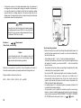
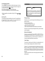
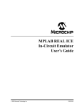
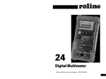
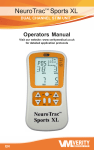
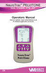
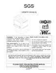
Model 703
True RMS Multimeter
Model 701
Multimeter
User’s Manual
Basic Specifications
DC Voltage
AC Voltage
703 (True RMS)
701
Basic Accuracy
WARNING!
SOURCES LIKE SMALL HAND-HELD RADIO
TR ANSCEIVERS, FIXED STA TION RA DIO
AND TELEVISION TRANSMITTERS, VEHICLE
RA DIO TR ANSM IT TERS AND CEL LUL AR
PHONES GENERATE ELECT ROMAGNET IC
RADIATION THAT MAY INDUCE VOLTAGES
DC Current
AC Current
703 (True RMS)
701
Resistance
Capacitance
Frequency
Duty Cycle
: 0 to 1000 V
: 15 mV to 1000 V (@ 40 Hz to 20 kHz)
: 0 to 1000 V (@ 40 Hz to 400 Hz)
: DC voltage – 0.5%
AC vol tage – 0.75%
: 0 to 10 A (20 A for 30 seconds)
: 20 µA to 10 A (20 A for 30 seconds)
: 0 to 10 A (20 A for 30 seconds)
: 0 to 40 MΩ
: 0.01 nF to 100 µF
: 0.5 Hz to 10 MHz
: 0.1 % to 99.9 % for 0.5 Hz to 500 kHz
(pulse width > 2 µsec.)
Diode Test
: 2.5 V
Continuity Check
: Beep at Approx. < 10 Ω (response time < 1 ms)
Temperature (703 only): –40°C to 1300°C (–40°F to 2372°F)
IN THE TEST LEADS OF THE MULTIMETER.
IN SU CH CASES THE ACCURA CY OF T HE
Warning
MULT IMETER C ANNOT BE GUARAN TEED
DUE TO PHYSICAL REASONS.
Read“Safety Information” before using this Meter.
CONTENTS
1. Safety Information
2. Electromagnetic Compatibility (EMC)
3. Controls and Indicators
4. Rotary Switch and Pushbutton Overview
5. Meter Operation
6. Maintenance
7. Specifications
2
3
4
7
9
19
20
1
1. SAFETY INFORMATION
This manual contains information and warnings that must be followed for operating
the meter safely and maintaining the meter in a safe operating condition.
If the meter is not used in a manner specified in this manual, the protection
provided by the meter may be impaired.
INTERNATIONAL ELECTRICAL SYMBOLS
AC (Alternating Current)
DC (Direct Current)
Either AC or DC
The Model 703 and Model 701 comply with IEC 1010-1 (1995), UL 3111-1 (6. 1994),
EN 61010-1 (1995), CSA C 22.2 No, 1010.1 - 92 ; Overvoltage 1000V Category III.
Caution! Refer to the explanation in this manual.
TERMS IN THIS MANUAL
Caution! Dangerous voltage (Risk of electric shock)
A Warning identifies conditions and actions that could pose serious hazards to the
user. A Caution identifies conditions and actions that could cause damage the
meter or the equipment under test.
Warning
Do not expose the meter to rain or moisture in order to reduce the risk of fire or
electric shock. To avoid any electrical shock hazard, observe the proper safety
precautions when working with voltages above 60 V dc or 30V ac rms, these
voltage lev els pose a potential shock hazard to the user. Inspect tes t leads,
connectors and probes for damaged insulation or exposed metal before using the
meter. If any defects are found, replace them immediately. Do not touch test lead
tips or the circuit being tested while power is applied to the circuit under test.
Alway s keep your fingers behind the finger guards of the test leads during
measurement. Do not measure any circuit that draws more than the protection
fuse’s current rating. Do not attempt the protection fuse’s voltage rating. Never
attempt a voltage measurement with the test lead inserted into the mA µA or A
input terminal. When servicing the meter, use only specified replacement parts.
Remove test leads from the meter before you open the battery door. Do not operate
the meter with the battery door removed or loosened. To avoid false readings,
which could result in possible electric shock or personal injury, replace the battery
as soon as the low battery indicator appears. Avoid working alone.
Earth (Ground)
Double insulation or Reinforced insulation
Fuse
Not Applicable to Identified Model
Battery
2. ELECTROMAGNETIC COMPATIBILITY (EMC)
+
The meters meet EN61326 : 1997 A1 : 1998. See the backside of this manual’s
cover page.
Caution
Dis connect the tes t l eads from the test points before changing functions .
Disconnect circuit power and discharge all high voltage capacitors before testing
resistance, continuity, capacitance or diodes. Always set the meter to the highest
range and work downward for an unknown value in the manual ranging mode.
Before measuring current, check the meter’s fuses and turn power OFF to the
circuit before connecting the meter to the circuit.
2
3
(1) 3-3/4 digit, 4000 count LCD display
3. CONTROLS AND INDICATORS
Although this manual describes the operation of both Model 701 and Model 703, all
illustrations and examples assume use of Model 703.
(2) Push-buttons for special functions & features
(3) Selector to turn the power ON or OFF and select a function
(4) Input terminal for 10A (20A for 30 sec.) current measurement function
(5) Input terminal for milli-amps and micro-amps current measurement function
(1)
(6) Common (Ground reference) input terminal for all measurement functions
(7) Input terminal for all functions EXCEPT current (A, mA, µA) measurement
functions
Glossary of Terms for Digital Multimeters
Average sensing RMS calibrated
(2)
(701)
(701)
(3)
4
(5)
(6)
(4)
(7)
RMS (Root-Mean-Square) is the term used to describe the effective or equivalent
DC value of an AC signal. Most digital multimeters use average sensing RMS
calibrated technique to measure RMS values of AC signals. This technique is to
obtain the average value by rectifying and filtering the AC signal. The average
value is then scaled upward (that is, calibrated) to read the RMS value of a sine
wave. In measuring pure sinusoidal waveform, this technique is fast, accurate, and
cost effective. However, in measuring non-sinusoidal waveforms, significant errors
can be introduced because of different scaling factors relating average to RMS
values.
True RMS
True RMS is a term which identifies a DMM that ac curately responds to the
effective RMS value regardless of the waveform shapes such as square, sawtooth,
triangle, pulse trains, spikes, and transient glitches as well as distorted waveforms
with the presence of harmonics.
5
Non-sinusoidal waveforms may cause :
– Overheated transformers, generator and motors to burn out faster than normal
– Circuit breakers to trip prematurely
– Fuses to blow
– Neutrals to be overheated due to the triplen harmonics present on the neutral
– Bus bars and electrical panels to vibrate
Crest Factor
Crest Factor is the ratio of the Crest (instantaneous peak) value to the True RMS
value, which is commonly used to define the dynamic range of a True RMS DMM.
A pure sinusoidal waveform has a Crest Factor of 1.414.
A badly distorted sinusoidal waveform normally has a much higher Crest Factor.
NMRR (Normal Mode Rejection Ratio)
4. ROTARY SWITCH AND PUSHBUTTON OVERVIEW
Turning the Meter On
To turn the meter on, turn the rotary switch from OFF to any switch setting.
Rotary Switch
Turn the meter on by selecting any measurement function. The meter presents a
standard display for that func tion (range, meas urement units , etc.). Use the
SELECT button to select any rotary switch alternate function.
When you turn the rotary switch from one function to another, a display for the new
function appears. Button choices made in one function do not carry over into
another function.
OFF. Turns the meter off.
NMRR is the DMM’s ability to reject unwanted AC noise effect which can cause
inaccurate DC measurements. NMRR is typically specified in terms of dB (decibel).
The Meter has a NMRR specification of > 60dB at 50Hz/60Hz, which means a good
ability to reject the effect of AC noise in DC measurements.
. (Model 701). Volts ac.
CMRR (Common Mode Rejection Ratio)
. (Model 701). Volts dc.
Common mode voltage is voltage existing on both the COM and Voltage input
terminals of a DMM, with respect to ground. CMRR is a DMM’s ability to reject
common mode voltage effect which can cause digit rattle or offset in voltage
measurements. The Meter has a CMRR specification of > 60dB at DC to 60 Hz in
AC volts measurement function and > 120 dB at DC, 50Hz and 60Hz in DC volts
measurement function.
. (Model 703). Volts ac rms and Volts dc.
Ω
. Access to resistance measurement, continuity test and diode test.
Hz (Duty). Frequency measurement. Duty cycle is also displayed if it is toggled by
the Hz / Duty button.
CAP. Capacitance measurement.
Burden Voltage
Burden voltage is a voltage drop across the input terminals of a current-measuring
device, caused by internal shunt resistance.
Burden voltage contributes measurement error, and should be as low as practical.
Temperature Coefficient
Temperature Coefficient is a factor used to calculate the change in indication or
output of an instrument with changes in temperature.
Uncompensated changes in temperature contribute uncertainty by an amount
determined by the temperature coefficient to instrument.
6
Temp (Model 703 only). Temperature measurement in degrees Centigrade or
Fahrenheit. Changing the reading mode should be preset at the factory.
. Micro-amps ac rms and micro-amps dc measurements (Model 703).
Micro-amps ac and micro-amps dc measurements (Model 701).
. Milli-amps ac rms and milli-amps dc measurements (Model 703).
Milli-amps ac and milli-amps dc measurements (Model 701).
7
. Amperes ac rms and amperes dc measurements (Model 703)
Amperes ac and amperes dc measurements (Model 701)
Pushbuttons
The buttons activate features that augment the function selected with the rotary
switch.
RANGE. Use the RANGE button to manually select a range. Press and hold
RANGE button for two seconds to return the meter to auto range mode. The meter
is in auto range mode when the AUTO indicator is on. The RANG E selection
function is not available in Hz (Duty), CAP, and Temp modes.
5. METER OPERATION
Voltage (
or
,
) Measurements
Voltage is the difference in electrical potential between two points.
The polarity of ac (alternating current) voltage varies over time, while the polarity of
dc (direct current) voltage is constant over time.
function defaults at dc . Press SELECT button momentarily to select ac.
Range available in volts functions are :
400 mV, 4 V, 40 V, 400 V, and 1000V
6
The range and units are displayed on the LCD.
REL△. Use this button to set the meter to relative ( △ ) mode and make relative
measurements. Relative zero allows the user to offset the meter consecutive
measurements with the displaying reading as the reference value. Practically all
displaying readings can be set as relative reference value. Press the REL △ button
momentarily to activate and to exit relative zero mode.
When measuring voltage, the meter acts like a 10MΩ (10 x 10 Ω) impedance in
parallel with the circuit. This loading effect can cause measurement errors in highimpedance circuits. In most cases, the error is negligible (0.1 % or less) if the circuit
impedance is 10 kΩ or less.
Hz/Duty. Press this button to toggle between the Hz measurement mode and the
Duty measurement mode when the selector switch is set to Hz (Duty),
and
.
HOLD. Press this button to turn hold mode ON and OFF. When the hold mode is
activated, the meter beeps, freezes the display, and displays the D.H indicator on
the LCD. HOLD mode freezes the display for later view.
(Backlight). Press the HOLD (
) button for two seconds to turn the
backlight ON or OFF, when the HOLD function is simultaneously activated with the
D.H symbol on the display. Press the HOLD button momentarily again to activate
the Backlight function only.
SELECT. Press this button to toggle between the dc measurement mode and the
ac measurement mode when the rotary selector switch is set to
(Model 703
only),
,
and
. And also press this button to cycle through Ω or
or
measurement mode when the rotary selector switch is set to Ω
.
8
Tips for measuring voltage
• In 400 mV range, displayed value may fluctuate when disconnecting input
terminals. This is normal.
• AC voltage measuring circuit in Model 703 is of root-mean-square (True RMS)
value system so the meter can accurately measure ac voltage of non-sinusoidal
waveforms including harmonics caused by various non-linear loads.
9
• To improve the accuracy of dc voltage measurements taken in the presence of
ac voltages (such as, measuring the dc voltage of an amplifier in the presence of
an ac signal), measure the ac voltage first. Note the just measured ac voltage
range and select a dc voltage range that is the same or higher than the ac
voltage range. This method improves the dc voltage accuracy by preventing the
input protection circuits from being activated.
Warning
To avoid the risk of electrical shock and instrument damage,
input voltages must not exceed 1000 V dc or ac (rms). Do not
attempt to take any unknown voltage measurement that may
be in excess of 1000 V dc or ac (rms).
Resistance ( Ω ,
,
) Measurements
(Ohms, Diode, and Continuity)
Tips for measuring resistance
Caution
To avoid damaging the meter or the equipment under test,
remove all power from the circuit and discharge all highvoltage capacitors before measuring resistance.
• Because the meter’s test current flows through all possible paths between the
test probe tips, the measured value of a resistor in a circuit is often different from
the resistor’s rated value.
• The test leads can add 0.1 Ω to 0.2 Ω of error to resistance measurements.
To measure the resistance of the leads, touch the probe tips together and read
the resistance. If necessary, you can press the REL△ button to automatically
subtract this value.
Resistance is an opposition to current flow. The unit of resistance is the ohm (Ω).
The meter measures resistance by sending a small current through the circuit.
• The resistance function can produce enough voltage to forward-bias silicon diode
or transistor junctions, causing them to conduct.
Do not use the 40 MΩ range for measuring the in-circuit resistance to avoid this.
Ranges available in resistance functions are :
• When meas uring large resi stance, reading may be uns tabl e due to
environmentally induced elec trical noise. In this case, directly connect the
resistor to input terminals of the meter or shield the resistor at potential of the
COM input terminal to obtain stable reading.
• For resistance above 1 MΩ, the display may take a few seconds to stabilize. This
is normal for high resistance readings..
• The meter has a circuit to protect the resistance range from over-voltage.
However, to prevent accidentally exceeding the protection circuit’s rating and to
ensure a correct measurement, NEVER CONNECT THE LEADS TO A SOURCE
OF VOLTAGE when the rotary switch is set to Ω or
or
functions.
400.0 Ω, 4.000 kΩ, 40.00 kΩ, 400.0 kΩ, 4 MΩ, and 40 MΩ
10
11
Diode (
) Test
Caution
Caution
Discharge all high-voltage capacitors before testing diodes.
Large value capacitors should be dis charged through an
appropriate resistance load.
Use the diode test to check diodes, transistors, silicon controlled rectifiers (SCRs),
and other semic onductor dev ic es. T he test s ends a curr ent thr ough a
semiconductor junction, then measures the junction’s voltage drop.
Using resistance and continuity function in a live circuit will
produce false results and may damage the instrument.
In many cas es the s uspic ious c omponents mus t be
disconnected from the circuit under test to obtain accurate
results.
Frequency (Hz) Measurements
Frequency is the number of cycles a signal completes each second. The meter
measures the frequency of a voltage or current signal by counting the number of
times the signal crosses a threshold level each second.
To measure the frequency of a voltage or current signal, press the Hz/Duty button
momentarily while measuring volts or currents.
The available frequency ranges are 5 Hz, 50 Hz, 500 Hz, 5 kHz, 50 kHz, 500 kHz,
5 MHz and 10 MHz.
Normal forward voltage drop (forward biased) for a good silicon diode is between
0.4 V to 0.9 V. A reading higher than that indicates a leaky (defective) diode. A
zero reading indicates a shorted (defective) diode.
An
indicates an open diode (defective).
Reverse the test leads connections ( reverse biased ) across the diode.
The display shows
if the diode is good. Any other readings indicate the diode
is shorted or resistive ( defective ).
Continuity (
) Test
The continuity function detects intermittent opens and shorts lasting as little as 1
millisecond. These brief contacts cause the meter to emit a short beep. This
function is convenient for checking wiring connections and operation of switches.
A continuous beep tone indicates a complete wire.
12
13
Tips for measuring frequency
Tips for measuring capacitance
• In frequency, the meter is always autoranging.
• When disconnecting the input terminals, the overload sign may be displayed or
the display may unsteadily fluctuate. This is typical.
• In capacitance, the Meter is always
autoranging.
• In 40 nF r ange, the readings ar e
probably unstable due to envir onmentally induced electrical noise and
floating capacity of the tes t leads .
Therefore, directly connect the object
to be measured to the input terminals.
Duty Cycle Measurements
Duty Cycle (or Duty Factor) is the percentage of time a signal is above or below a
trigger level during one cycle.
The duty cycle mode is optimized for measuring the ON or OFF time of logic and
switching signals. Systems such as electronic fuel injection systems and switching
power supplies are controlled by pulses of varying width, which can be checked by
measuring duty cycle.
Press the Hz/Duty button to toggle between the Hz mode and the Duty Cycle mode
when the rotary selector knob is set to Hz (Duty),
,
,
, or
.
Capacitance Measurements
Caution
Temper ature (Temp) Measurements [Model 703 only]
To avoid damaging the meter or the equipment under test,
remove all power from the circuit and discharge all highvoltage capacitors before measuring capacitance.
Large value capacitors should be discharged through an
appropriate resistance load. Use the dc voltage function to
confirm that the capacitor is discharged.
The meter c omes wi th temperatur e
reading in either Centigrade or
Fahrenheit preset at the fac tory. The
reading mode can be c hanged at the
factory only.
Capacitance is the ability of a component to store an electrical charge.
The unit of capacitance is the farad (F). Most capacitors are in the nanofarad (nF)
to microfarad (µF) range.
WARNING
Do not apply thermoc oupl e to
circuits exceeding 30V rms, 42.4V
peak or 60V dc.
The available capacitance ranges are 40nF, 400 nF, 4 µF, 40 µF, and 100 µF.
14
※ The SELECT function is not available
in Temperature mode.
Be sure to insert the banana plug K-type
temperature bead probe TP7 with correct
+ – polari ties. You can als o us e a
thermocoupl e probe adapter T P1 A
(O ptional purc has e) to adapt other
standard K-type temperature probes.
15
Current (
,
,
) Measurements
Warning
Never attempt an in-circuit current measurement where the
open-circuit potential to earth is greater than 1000V. You may
damage the meter or be injured if the fuse blows during such
a measurement.
4. Turn on power to the circuit and read the display.
5. After measuring current, turn off power to the circuit and discharge all highvoltage capacitors. Dis connect the meter and restore the circuit to normal
operation.
Caution
Check the meter fuses before measuring current. Use the
proper terminals , functi on, and range for c urrent
measurements. Never place the probes in parallel with any
circuit or component when the test leads are plugged into the
current terminals.
Current is the flow of electrons through a conductor. To measure current, you must
open the circuit under test, then place the meter in series with the circuit.
The available current ranges are :
400.0 µA, 4000 µA, 40.00 mA, 400.0 mA, 4.000 A, and 10.00 A
The meter defaults at dc. Press SELECT button momentarily to select ac.
To measure dc or ac current,
1. Turn off power to the circuit and discharge all high-voltage capacitors.
2. Insert the black lead into the COM terminal and the red lead into an input
terminal appropriate for the measurement range as the following table.
Range
Input
Ranges
mAµA
400.0 µA, 4000 µA
mAµA
40.00 mA, 400.0 mA
10A
4.000 A, 10.00 A
※ To avoid blowing the meter’s 440 mA fuse, use the mAµA terminal only if you are sure the
current is less than 400 mA.
3. Open the current path to be tested. Touch the red probe to the more positive
side of the break and touch the black probe to the more negative side of the
break. (Reversing the leads will produce a negative reading, but will not damage
the meter.)
16
SERIES CONNECTION
SERIES CONNECTION
Tips for measur ing current
• When measuring a 3-phase system, special attention should be taken to the
phase to phase voltage which is significantly higher than the phase to earth
voltage. To avoid exceeding the voltage rating of the protecti on fus e(s)
accidentally, always consider the phase to phase voltage as the working voltage
for the protection fuse(s).
• When measuring current, the meter’s internal shunt resistors develop a voltage
across the meter’s terminals called “burden voltage”.
This voltage drop may affect precision circuits or measurements.
17
Auto / Manual Range Operation
6. MAINTENANCE
Press the RANGE button momentarily to select manual-ranging in volts, ohms,
and currents measurement function, and the meter will remain in the range it was
in, when the LCD annunciator AUTO turns off.
Press the button momentarily again to step through the ranges.
Press and hold the RANGE button for 2 seconds to resume auto- ranging.
※ Manual-ranging feature is not available in Hz (Duty), CAP, Temp,
functions.
and
Auto - Power - Off
The Auto-Power-Off feature automatically turns the meter off to extend battery life
after approximately 30 minutes of no activities. To turn on the meter after AutoPower-Off, turn the rotary switch from OFF to any function (ON).
Warning
To avoid electrical shock or personal injury, remove the test
leads and any input signals before replacing the battery or
fuses. To prevent damage or injury, install only the same type
of fuses or equivalents.
Cleaning and Storage
Periodically wipe the case with a damp cloth and mild detergent; do not use
abrasives or solvents.
Clean the input terminals as follows :
1. Turn the meter off and remove all test leads.
2. Shake out any dirt that be in the terminals.
3. Soak a new swab with alcohol and work the swab around in each terminal.
If the meter is not to be used for periods of longer than 60 days, remove the battery
and store it separately.
Battery and Fuse Replacement
The meter uses a single standard 9V battery (NEDA 1604, JIS006P, IEC 6F 22), a
1000 V/440 mA IR 10 kA fast acting F fuse (F71 ) for mAµA current input, and a 1000
V/11 A IR 10KA fast acting F fuse (F 72) for A current input. The (F 71) 440 mA, (F 72 ) 11
A fuse must be replaced by qualified service personnel only.
Trouble Shooting
If the meter fails to operate even with the battery or fuse replacements, check it
twice over according to operating procedure as described in this manual.
If the meter’s V/Ω input terminal has subjected to high voltage transient (caused by
lightning or switching surge to the system) by accident or abnormal operating
conditions, the series fusible resistors will be blown off like fuses in order to protect
the user and the meter. Most measuring functions through this terminal will then be
open circuit.
In this case, the series fusible resistors and the spark gaps should be replaced by
qualified personnel.
18
19
Battery Life
: 250 hrs. typical (with backlight off) [703]
750 hrs. typical (with backlight off) [701]
Safety & Compliances
Shock Vibration
: Per MIL-T-PRF 28800 for Class II instruments
Maximum voltage between any terminal
and earth ground
: 1000 V ac/dc
Pollution Degree
: 2
Compliances
: Complies with CSA C22.2 No 1010.1-92,
ANSI/ISA-S82, 01-94 to 1000 V Overvoltage
Category lll.
Electromagnetic
Compatibility (EMC)
Certifications
: UL & cUL standard UL 3111-1 Listed
CE-marking certificated
Surge Protection
: 8 kV peak per IEC 1010.1-92
7. SPECIFICATIONS
Fuse Protection for mA or µA inputs : 1000 V / 440 mA lR 10 kA FAST fuse
Fuse Protection for A input : 1000 V / 11 A lR 10 kA FAST fuse
Physical Specifications
: Susceptibility – Commercial Limits for
EN 50082-1
Emissions – Commercial Limits for EN 50081-1
Size (H x W x L)
: 40.5 x 92 x 172 mm
Weight
: Approx. 386g
Calibration Interval
: 1 year
Feature Summary
Backlight
: For clear readings in poorly lighted areas
Display (LCD)
: Digital – 4000 counts display;updates
5 times/sec.
Fast Autoranging
: Meter automatically selects the best range
momentarily
Operating Temperature
: 0°C to 40°C
HOLD
: Holds readings on display
Storage Temperature
: –20°C to 60°C
Continuity / Open test
: Beeper sounds
Temperature Coefficient
: nominal 0.15 x (specified accuracy) / °C
@(0°C to 18°C or 28°C to 40°C),
or otherwise specified
Battery/Fuse Access Door
: battery or fuse replaceable without voiding
calibration
High-Impact Overmolded Case
: Protective holster features
Relative Humidity
: 0 % to 80 % @ (0°C to 35°C)
0 % to 70 % @ (35°C to 40°C)
Altitude
: Operating – up to 2000m
Storage – 10000m
Battery Type
: Single 9V battery –NEDA 1604, JIS 006P or
IEC 6F 22
20
21
Electrical Specifications
DC Current
Accuracy is given as ± ([% of reading] + [number of digits]) at 18°C to 28°C with
relative humidity up to 80%, for a period of one year after calibration.
True RMS responding accuracies are specified from 5% to 100% of range or
otherwise specified; Crest Factor < 3:1 at full scale and < 6:1 at half scale.
DC Voltage
Range
Resolution
400 mV
4V
40 V
400 V
1000 V
100 µV
1 mV
10 mV
100 mV
1V
NMRR
CMRR
Input Impedance
Accuracy
701
703
0.5 % + 2
0.5 % + 2
0.75 % + 3
0.75 % + 3
: > 60dB @ 50/60 Hz
: > 120 dB @ DC, 50/60 Hz, Rs=1kΩ
: 10 MΩ, 30 pF nominal
(50 MΩ, 100 pF nominal for 400 mV range)
Accuracy
Resolution
400 mV
4V
40 V
400 V
1000 V
CMRR
Input Impedance
40 Hz – 400 Hz
100 µV
1 mV
10 mV
100 mV
1V
400 Hz – 1 kHz
703
2.0 % + 10
703
2.0 % + 10
0.75 % + 3
0.75 % + 3
2.0 % + 3
1.0 % + 5
2.0% + 5 *1
: > 60dB @ DC to 60 Hz, Rs = 1 KΩ
: 10 MΩ, 30 pF nominal
(50 MΩ, 100 pF nominal for 400 mV range)
*1: Accuracy for 400 Hz to 1 kHz
400 µA
4000 µA
40 mA
400 mA
4A
10 A
0.1 µA
1 µA
10 µA
100 µA
1 mA
10 mA
Accuracy
701
703
1.0% + 2
1.0% + 2
1.5 % + 5
1.5 % + 5
AC Current
Range
Accuracy
Resolution
40 Hz – 400 Hz
701
703
0.1 µA
1 µA
10 µA
100 µA
1 mA
10 mA
400 Hz – 10 kHz
703
1.0 % + 5
1.0 % + 5
1.5 % + 5
1.5 % + 10
1.5 % + 10
2.0 % + 10
1 kHz – 20 kHz
701
1.0% + 5
Resolution
400 µA
4000 µA
40 mA
400 mA
4A
10 A
AC Voltage
Range
Range
Resistance
–
Range
Resolution
400 Ω
4 kΩ
40 kΩ
400 kΩ
4 MΩ
40 MΩ
0.1 Ω
1Ω
10 Ω
100 Ω
1 kΩ
10 kΩ
Accuracy
701
703
1.0 % + 5
1.0 % + 5
0.5 % + 3
0.5 % + 3
1.0 % + 5
1.5 % + 10
1.0 % + 5
1.5 % + 10
Open Circuit Voltage : < 1.3 V dc
22
23
Continuity
Temperature (Model 703 only)
Audible threshold
: the beeper sounds if the measured resistance is lower than
10 Ω, and turns off when greater than about 60 Ω.
Response time
: < 1 msec.
Diode Test
Range
Accuracy
Test Current
(Typical)
Open Circuit Voltage
4V
2%
0.25 mA
< 1.5 V dc
Capacitance
Range
* 40 nF
1
400 nF
4 µF
40 µF
100 µF
Range
Resolution
Accuracy
- 40°C to -10°C
(-40°F to 14°F)
- 10°C to 400°C
(14°F to 752°F)
400°C to 1300°C
(752°F to 2372°F)
1 °C
1 °F
1 °C
1 °F
1 °C
1 °F
3% ± 5°C
(3% ± 5°F)
1% ± 3°C
(1% ± 3°F)
3% of reading
(3% of reading)
* This specification is effective at the ambient temperature of 23°C (73.4 °F) only.
Frequency Counter Sensitivity
Accuracy *1
Resolution
10 pF
100 pF
1 nF
10 nF
100 nF
701
703
2.5 % + 10
2.5 % + 10
*1. Accuracy with film capacitor or better
Using △ Mode
Range
V
(4 V to 1000 V)
µA
(400 µA to 4 mA)
mA
(40 mA to 400 mA)
A
(4.0 A to 10 A)
Minimum Sensitivity ( RMS Sine Wave )
40 Hz to 10 kHz
40 Hz to 20 kHz
500 mV
500 mV
> 15 % F.S. of AC range
Not Specified
> 15 % F.S. of AC range
Not Specified
> 45 % F.S. of AC range
Not Specified
Frequency and Duty Cycle
Range
5 Hz
50 Hz
500 Hz
5 kHz
50 kHz
500 kHz
5 MHz
10 MHz
0.1% to
99.9%
24
Resolution
Accuracy
701
703
0.001 Hz
0.01 Hz
0.1 Hz
1 Hz
10 Hz
100 Hz
1 kHz
10 kHz
0.1%
Remark
Function
Minimum frequency :
0.5 Hz
0.05 % + 3
0.05 % + 3
Burden Voltage ( A, mA, µA)
Sensitivity :
5 Hz–1 MHz, > 250 mV
1 MHz–10 MHz, > 350 mV
mA / µA
10 A
Range
Burden Voltage (typical)
400 µA
4000 µA
40 mA
400 mA
150 µV / µA
150 µV / µA
3.3 mV / mA
3.3 mV / mA
4A
10 A
0.03 V / A
0.03 V / A
0.5 Hz to 500 kHz (pulse width > 2 µsec.)
(0.1% + 0.05% per kHz + 1 count) for 5 V input (Logic signals only)
25