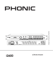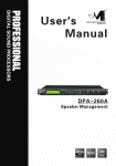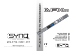
1
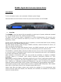
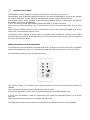
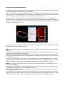
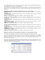
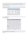
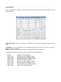
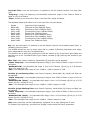
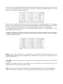
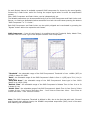
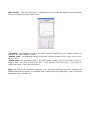
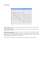
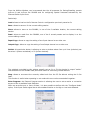
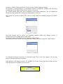
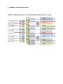
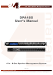
DP A - 8 80T
8 I n - 8 O ut Digital Matrix Mixer
482mm
19"
DIGITAL
USB
DPA880 Digital 8x8 Conference System Matrix
User Manual
For the microphone inputs, can be selected a Phantom power Supply.
Described below are the functions of the front panel control buttons for the DPA880.
•
Overview
The DPA880 on the front panel offer the possibility to select up to 6 presets, edited and uploaded
on the unit through the Pc Sw, thanks to 6 push buttons.
The Name of the current preset is displayed on a wide 2x24charachters LCD and the main
activities of the unit's channels are shown by 8 rows of 5 leds: Line, Microphone, Feedback,
Signal/Clip, Limiter.
Anyone of the 6 available presets can even be recalled by a remote Wall Panel Control, allowing
also the control of the Master Output Volume.
The Wall Remote Control, acting through a RS485 connection, and the Remote PC control, via
USB, can operate simultaneously.
When not used for the Wall Panel Remote Control, the RS485 connection can be used for the
creation of a DPA880 network of up to 32 units, all controlled by the Ps Sw remote control.
The DPA880 is a powerful Matrix, allowing to select as input, for any of the 8 input independently,
a Line Level Input or a Microphone Input, where for the microphone input there is the possibility
to provide a 48V Phantom Power supply.
When selected a microphone Input, the unit provide the possibility to activate a Feedback
Eliminator based on a powerful “pitch shifting” algorithm, particularly effective for voice
applications.
Each output has as first stage an 8x8 Matrix allowing the mix of the 8 inputs and processing the
final mix with a 5 bands Eq, with filters assignable as Peaker or Hi/Low Shelving, able to range
from -15dB up to +15dB gain; following the 5bands Eq, a Hp and a LP filters up to 24dB/Oct
shape the output channel band's limits; a delay is also available for signal/speakers alignments.
The Dynamic process of each output channel is left to a powerful RMS Compressor, with variable
Ratio and to a final Peak Limiter for the complete output peak control.
Master Input Gain and Master output Level controls are available for the simultaneous level
control of the all inputs and outputs; four Switches, Sw controlled, are available for the On/Off
control of remote devices.
•
Getting Started
The DPA880 can work as a stand alone unit [Stand Alone Mode], where up to 6 preset can be
recalled by directly selecting them through the 6 “preset” buttons available on the front panel, or
can work as completely remotely controlled unit [Remote Control Mode].
As soon as is turned ON the device will Load the currently selected preset.
During the Preset Loading, the LCD screen will show the following:
DPA880
Here the unit is just checking if Presets are available on the Eeprom.
If not, the “Init” phase can last several seconds, and the Eeprom of the unit is initialized in order
to guest later on the presets will be created by the user through the Pc Remote Control Sw.
If Presets are already available, then the “init” phase will be skipped and the currently selected
preset will be loaded:
The preset loading can take approximately 14Seconds and will end with showing on the LCD the
currently running preset's name:
DPA880
01: Current Preset Name
•
Stand Alone Mode
When the DPA880 is operating as stand alone unit, so running one of the 6 available presets,
previously created and stored within the unit with the remote control Pc Sw, the only available
control are the 6 “preset buttons”, allowing to select 1 of the 6 available presets previously stored
through the Pc Sw Remote Control.
The name of the currently loaded/running preset is displayed on the LCD screen.
In Stand Alone Mode, the “Activity” of the DPA880 in terms of running processes and signal
status, per each channel, can be checked thanks to the Vu-Metering features:
1 led for Microphone Phantom Power Supply Active
5 led for Outputs Activities:
Line
Mic
Feedback
Sign/Clip
Limit
Line input Selected
Microphone input Selected
Feedback Active (available ONLY if selected Mic Input)
Turning on Blue when present Signal on the channel and turning Red when
the signal is clipping
Showing the RMS Compressor or the Peak Limiter activity
•
DPA880 Main Features
Maximum Delay:
380.998ms by 21us increment/decrement step, on each
Output
Parametric Equalization:
3 filters on each Input (when selected Line input or Mic without
feedback eliminator active) assignable as Bell or Shelving
5 filters on each Output assignable as Bell or Shelving
Filters:
Symmetrical Bell or High/Low Shelving up to second order
Filter gain:
for Bell and Shelving the gain is ranging from -15dBu up
to +15dBu by 0.5dBu resolution steps
Center frequency:
selectable with a 1/24th of octave resolution steps from
20Hz up to 20kHz
Filter Q/BW:
Q/BW from 0.4/3.59 up to 10/0.0312 by 0.1 resolution steps (Q)
Each Filter of the Eq can be singularly “Bypassed” once set.
HPF on Outputs:
from 1st order (Butterworth -6dB/Oct) up to 4th Order
(Butterworth, Linkwitz or Bessel -24dB/Oct)
LPF on Outputs:
from 1st order (Butterworth -6dB/Oct) up to 4th Order
(Butterworth, Linkwitz or Bessel -24dB/Oct)
Filter’s Cutting Frequency steps: 1/24th of octave
RMS Compressor on Outputs
Threshold:
from 18dBu up to -12dBu
Attack time:
Attack time from 5ms up to 200ms (1ms resolution up to
20ms, then 10ms resolution up to 100ms and 20ms res. up to
200ms)
Release time:
Release time from 0.1 sec up to 3 sec (0.1sec resolution)
Ratio:
1:1 (Bypass) up to 32:1 (Limiting), with Ratio Slope computed
on Log Table with 0.1dB steps precision
Knee:
Soft/Hard
Peak Limiter on Outputs
Threshold:
from 20dBu up to -10dBu
Attack time:
Attack time from 5ms up to 200ms (1ms resolution up to
20ms, then 10ms resolution up to 100ms and 20ms res. up to
200ms)
Release time:
Release time from 0.1 sec up to 3 sec (0.1sec resolution)
•
Remote Control Mode
The DPA880 is mainly thought to operate with Remote Control Sw running on Pc.
Nevertheless, once created the desired presets for the defined applications, the unit can operate
as a Stand Alone one, as seen before or as Wall Panel Remote Control working device.
The Remote control, when operated by the Wall Panel Remote control, is working on the base of
the RS485 connector of the DPA880
The Pc Sw remote control, can instead operate with USB or RS485 connection.
When used the USB connection, the Pc Sw Remote Control can control/edit ONLY one unit per
time.
When used the RS485 connection, the Pc Sw Remote Control can control/edit MORE units at the
same time, connected each others in net.
A particular way of “double” Remote Control is allowed, being possible to connect to the RS485
the Wall Panel Control and at the same time the Pc Sw Remote Control can be used if connecting
the Pc on the USB connection.
Wall Panel Remote Control Operations
The DPA880 can be controlled by a Remote Wall Panel, allowing to load one of the first 4 available
presets stored within the unit, or to increase/decrease the Main output Volume of the unit itself.
The Wall Panel Remote Control is looking as follow
The buttons “Preset 1” to “Preset 4” are used to load one of the first 4 presets stored within the
DPA880
Once selected the desired preset, the related led will turn ON.
The buttons “Up/Down” can be used to increase/decrease the DPA880 Output Level.
A “Lock” key is available in order to “lock/unlock” the Preset and Up/Down buttons, so to inhibit
their use.
When the buttons are locked, the “unlocked” led will be Off.
The Wall Panel Remote Control has to be connected to the RS485 connector of the DPA880
PC Sw Remote Control Operations
The DPA880 can be controlled by a Remote Control Sw running on Pc, allowing to fully edit the all
processes available on each channel of the DPA880.
More, once created the desired configurations and selected the desired processes, the complete
channels' set up can be stored within the DPA880 and recalled later on as preset also when the
unit is working in Stand Alone Mode or as Wall Control Panel operating unit.
Once launched the Pc Sw Remote Control, previously installed on Pc (for the installation it is
enough to run the “Installation Sw” and to install also the USB driver which installation instruction
are on the CD containing the Remote Control Sw and coming with the DPA880), the following
screen shot will appear on the Pc:
The screen above is allowing to select what kind of connection has to be used and to set the
parameters for the selected connection.
USB: the USB connection has to be selected when the DPA880 is connected to the PC through the
USB line.
In this case the DPA880 will be controlled as ONE ONLY unit, not being allowed the net control of
more units when using the USB connection.
Nevertheless, when using the USB connection, the Pc Remote Control Sw can operate at the same
time of the Wall Panel Remote Control, there where the Wall Panel Remote Control is connected to
the RS485 connection.
In the USB mode (chosen by “checking” the USB button on the “Communication Port” frame),
need to assign the proper “COM” port in order to match the COM port assigned by the Pc to the
“USB to Serial Port” within the Device Manager window at the “Ports (COM&LPT)” directory.
RS485: the RS485 connection has to be selected when the DPA880 is connected to the PC
through the RS485 line.
In this case the DPA880 will be controlled as one of a NET of chained units, being allowed the net
control of more units when using the RS485 connection.
When using the Rs485 connection, the Pc Remote Control Sw cannot operate at the same time of
the Wall Panel Remote Control.
In the RS485 mode (chosen by “checking” the RS485 button on the “Communication Port” frame),
need to assign the proper “COM” port in order to match the COM port assigned by the Pc to the
“USB to Serial Port” within the Device Manager window at the “Ports (COM&LPT)” directory.
When selected the RS485 connection, more DPA880 can be connected all together.
In order this to happen, need the all units (connected in net and up to 32) to be identified by
DIFFERENT ID number.
In order the units to have a different ID, need to pre-assign to the all units used in net a specific
ID number.
When selected the RS485 mode, this can be done connecting one by one the units to be used in
net and assigning to anyone of them an ID through the “Configure ID Device” button.
When a Unit is connected, pressing the “Configure ID Device” it is possible to enter a window
allowing to assign to the unit the ID number.
NOTE: for avoiding problems is highly suggested to work with COM ports number within the 10.
If the Pc will assign to the USB connection a COM port exceeding the number 10, please force to
assign a port from 1 to 9.
Once selected the desired connection, pressing the “>>” button the Main Environment Window of
the Pc Sw will open:
And the DPA880 LCD will notify that the unit is controlled remotely:
System Lock
PC Connection
If the DPA880 is operating through an USB connection, then on the left vertical bar will be
displayed the only name of the connected unit.
If the DPA880 is operating through a RS485 connection, then on the left vertical bar will be listed
the all names and Ids of the net connected units.
Double clicking on the Unit's name which processes/parameters have to be edited, the editing
environment of the selected unit will open.
Inputs Page
From the “Input” Page of the editing environment, on each input can be selected the source.
This can be Microphone or Line.
When the Line Source is selected, the Input Gain can be adjusted from -127dB up to +6dB.
A Bypass button is available for any channel, allowing to “Bypass” the channel's level setting and
bringing it to 0dB.
A Master Gain can be used to Mute the all Inputs (0%) or to bring all of them to a level up to 0dB
(100%).
For each input, is possible to set the signal Phase as “Direct” (unchecked box) or 180Deg.
Reversed (box checked).
A 3 bands Equalizer is ever available and can be set pressing the “Edit” button.
In a such case, the following Eq editing window will open
EQ: from this sub-frame it is possible to set the Input Channels three available Peaker (Bell) or
variable Q Shelving Filters.
The DPA880 allows the user to select either Bell or variable Q Shelving Parameters and assign
them independently using the 3 available filters.
The selection can be done just pressing the “Peak Eq” button on top of the filters' gain sliders and
selecting one of the 3 available filters' type: Peaker, variable Q high Shelving and variable Q low
Shelving.
BELL Filter: here Center Frequency, Band Width (Q) and Gain can be adjusted.
“Center Frequency”: the selectable frequencies range is from 20Hz to 20kHz in steps of 1/24 of
an Octave.
“Bandwidth BW”: the selectable BW range is from 0.0312 Octave (Q=10) up to 3.59 Octave
(Q=0.4) in steps of 0.1 Q.
“Gain”: the selectable Gain range is from -12dB to +12dB in steps of 0.5 dB.
Variable Q Low Shelving Filter: here Center Frequency, Band Width (Q) (Slope) and Gain can
be adjusted.
“Center Frequency”: the selectable frequencies range is from 20Hz to 20kHz in steps of 1/24 of
an Octave.
“Bandwidth BW (Slope)”: the selectable BW range is from 0.0312 Octave (Q=10) up to 3.59
Octave (Q=0.4) in steps of 0.1 Q.
“Gain”: the selectable Gain range is from -12dB to +12dB in steps of 0.5 dB.
Variable Q High Shelving Filter: here Center Frequency, Band Width (Q) (Slope) and Gain can
be adjusted.
“Center Frequency”: the selectable frequencies range is from 20Hz to 20kHz in steps of 1/24 of
an Octave.
“Bandwidth BW (Slope)”: the selectable BW range is from 0.0312 Octave (Q=10) up to 3.59
Octave (Q=0.4) in steps of 0.1 Q.
“Gain”: the selectable Gain range is from -12dB to +12dB in steps of 0.5 dB.
Note: each single filter can be independently “bypassed” for an easy setting/use of them.
To “Bypass” the single filter, just press the “Bypass” button below the filter’s parameters.
In order to set, if necessary, more Eq of the 8 input channels in tha same way, “Input Linked”
buttons are available and, when pressed, force the all channels corresponding to the pressed
buttons to set the Eq in the same as as the one set for the currently edited channel (which has to
be one of the linked ones)
The set up of the filters and specially their frequency placement can also be done with the use of
the mouse, just activating the “Show Cursor” function, pressing the related button on the left
bottom of the frequency response Graphic.
Once the all 3 available cursor are shown on the Frequency Response graphic, just selecting
anyone of them with the mouse's arrow and maintaining the mouse's click pressed, it is possible
to move and place the selected cursor on the desired frequency and with the desired gain.
For setting the filter's Q, still need to enter the desired value directly in the dedicated box in the
filters' editing main sub-frame.
In order to see what's the “Phase” response of the channel once set up the all filters of the EQ, it
is possible, selecting the Phase choice on the top right of the Graphic window, to turn the graphic
in “Phase Response Graphic”:
When the Microphone Source is selected, on the related channel is possible to adjust the Input
level from -127dB up to 0dB.
No extra gain is allowed.
When selected microphone as input, the user can chose to select on the input itself a 3bands Eq
process on the Input signal, or a Feedback Eliminator.
When the 3 bands Eq is selected, the Equalizer can be edited in the same way shown for the Line
Input case.
When the Feedback Eliminator is selected, it can be activated or not, and when active, its speed
can be set.
The Feedback Eliminator is working on the base of a frequency shift process avoiding the feedback
to raise up.
The speed of the feedback elimination process it is just defining the amount of frequency shift is
added to the input signal.
Higher speed means higher immunity to feedback.
A Phantom power supply can be activated if microphones using a such power supply are chosen.
Note: at the bottom of the Meter Bar aside the level slider, both when Line or Microphone Input
are selected, there is an indicator indicating in real time and precisely what's the current Input
signal level in dBu
Note1: a “Balance” check box is also available.
When a Balanced Input is used, it has to be checked, so to get the proper input level adjustment.
If a Not Balanced Input is used, the box has to be left unchecked and the input level is
automatically adjusted at +6dBu.
Outputs Pages
From this windows is possible to access and edit the most significant signal processes of the 8
output channels.
High Pass Filter: from this sub-frame it is possible to set the Output Channels High Pass Filter
(HPF).
“Frequency”: (Low Cut frequency) the selectable frequencies range is from 20Hz to 20kHz in
steps of 1/24 of an Octave.
“Slope”: allows you to select the X-Over's High Pass Filter Shape and Order.
The available shapes and orders for the High Pass Filter are listed below:
–
–
–
–
–
–
–
–
–
Bypass
Buttw 6dB
Buttw 12dB
LRiley 12dB
Bessel 12dB
Buttw 18dB
Buttw 24dB
LRiley 24dB
Bessel 24dB
(High Pass Filter Bypassed)
(Butterworth Filter 6dB/Oct Slope)
(Butterworth Filter 12dB/Oct Slope)
(Linkwitz/Riley Filter 12dB/Oct Slope)
(Bessel Filter 12dB/Oct Slope)
(Butterworth Filter 18dB/Oct Slope)
(Butterworth Filter 24dB/Oct Slope)
(Linkwitz/Riley Filter 24dB/Oct Slope)
(Bessel Filter 24dB/Oct Slope)
Low Pass Filter: from this sub-frame it is possible to set the Output Channels Low Pass Filter
(LPF).
“Frequency”: (High Cut frequency) the selectable frequencies range is from 20Hz to 20kHz in
steps of 1/24 of an Octave.
“Slope”: allows you to select the X-Over's Low Pass Filter Shape and Order.
The available shapes and orders for the Low Pass Filter are listed below:
–
–
–
–
–
–
–
–
–
Bypass
Buttw 6dB
Buttw 12dB
LRiley 12dB
Bessel 12dB
Buttw 18dB
Buttw 24dB
LRiley 24dB
Bessel 24dB
(High Pass Filter Bypassed)
(Butterworth Filter 6dB/Oct Slope)
(Butterworth Filter 12dB/Oct Slope)
(Linkwitz/Riley Filter 12dB/Oct Slope)
(Bessel Filter 12dB/Oct Slope)
(Butterworth Filter 18dB/Oct Slope)
(Butterworth Filter 24dB/Oct Slope)
(Linkwitz/Riley Filter 24dB/Oct Slope)
(Bessel Filter 24dB/Oct Slope)
EQ: from this sub-frame it is possible to set the Output Channels five available Peaker (Bell) or
variable Q Shelving Filters.
The DPA880 allows the user to select either Bell or variable Q Shelving Parameters and assign
them independently using the 5 available filters.
The selection can be done just pressing the “Peak Eq” button on top of the filters' gain sliders and
selecting one of the 3 available filters' type: Peaker, variable Q high Shelving and variable Q low
Shelving.
BELL Filter: here Center Frequency, Band Width (Q) and Gain can be adjusted.
“Center Frequency”: the selectable frequencies range is from 20Hz to 20kHz in steps of 1/24 of
an Octave.
“Bandwidth BW”: the selectable BW range is from 0.0312 Octave (Q=10) up to 3.59 Octave
(Q=0.4) in steps of 0.1 Q.
“Gain”: the selectable Gain range is from -12dB to +12dB in steps of 0.5 dB.
Variable Q Low Shelving Filter: here Center Frequency, Band Width (Q) (Slope) and Gain can
be adjusted.
“Center Frequency”: the selectable frequencies range is from 20Hz to 20kHz in steps of 1/24 of
an Octave.
“Bandwidth BW (Slope)”: the selectable BW range is from 0.0312 Octave (Q=10) up to 3.59
Octave (Q=0.4) in steps of 0.1 Q.
“Gain”: the selectable Gain range is from -12dB to +12dB in steps of 0.5 dB.
Variable Q High Shelving Filter: here Center Frequency, Band Width (Q) (Slope) and Gain can
be adjusted.
“Center Frequency”: the selectable frequencies range is from 20Hz to 20kHz in steps of 1/24 of
an Octave.
“Bandwidth BW (Slope)”: the selectable BW range is from 0.0312 Octave (Q=10) up to 3.59
Octave (Q=0.4) in steps of 0.1 Q.
“Gain”: the selectable Gain range is from -12dB to +12dB in steps of 0.5 dB.
Note: each single filter can be independently “bypassed” for an easy setting/use of them.
To “Bypass” the single filter, just press the “Bypass” button below the filter’s parameters.
The set up of the filters and specially their frequency placement can also be done with the use of
the mouse, just activating the “Show Cursor” function, pressing the related button on the left
bottom of the frequency response Graphic.
Once the all 5 available cursor are shown on the Frequency Response graphic, just selecting
anyone of them with the mouse's arrow and maintaining the mouse's click pressed, it is possible
to move and place the selected cursor on the desired frequency and with the desired gain.
For setting the filter's Q, still need to enter the desired value directly in the dedicated box in the
filters' editing main sub-frame.
In order to see what's the “Phase” response of the channel once set up the all filters of the EQ, it
is possible, selecting the Phase choice on the top right of the Graphic window, to turn the graphic
in “Phase Response Graphic”:
Delay – from this sub-frame it is possible to set the Output Channels Delay Time from
000.0000mS (0 meters) up to 380.998mS (129.53932 Meters), by steps of 1mS (Adj arrows) or
20.8uS (Fine arrows).
Level [dB] – from this sub-frame it is possible to set the Output Channels Level from -127dB up
to +6dB.
Pressing the “Bypass” button at the bottom of the Level slider, the currently set level will be
skipped and the output level will be set to 0dB.
Phase – when this check box is “unchecked” the processed signal is left with its original phase.
When the check box is “checked”, then the original phase of the signal is inverted of 180Deg.
On each Output channel is available a powerful RMS compressor for improving the sound quality,
followed by a Peak limiter useful for limiting the output signal before to enter the amplification
system.
Each, RMS Compressor and Peak Limiter, can be independently set.
The editable parameters can be accessed directly from the RMS Compressor and Peak Limiter subframes, or entering a dedicated window accessible from both the sub-frames pressing the buttons
“RMS Compressor” or “P. Limiter”.
Both RMS Compressor and Peak limiter can be quickly skipped and re-activated by pressing the
“Bypass” button within the respective sub-frames.
RMS Compressor – from this sub-frame it is possible to set the Threshold, Ratio, Attack Time,
Release Time and “Knee” type of the Output Channels' RMS Compressor.
“Threshold”: the selectable range of the RMS Compressor's Threshold is from +18dBu (OFF) to
-12dBu in steps of 0.2dBu
“Ratio”: the selectable range of the RMS Compressor's Ratio is from 1:1 (Off) up to 32:1 (Lim) in
steps of 1.
“Hard/Soft Knee”: the selectable range of the RMS Compressor's Knee type is from 000%
(Hard) up to 100% (Soft).
“Release Time”: the selectable range of the RMS Compressor's Release Time is from 0.1s to 3s
in steps of 0.1s.
“Attack Time”: the selectable range of the RMS Compressor's Attack Time is from 5ms to 200ms
in steps of 1ms - from 5ms to 20ms then 5ms - from 20ms to 30ms then 10ms - from 30ms to
100ms and 20ms - from 100ms to 200ms.
Note: The RMS Compressor Threshold is defined in dBu, due to the fact that with both, Sinusoid
and Squared wave testing signals, the DPA880 compressed output dBu (RMS) Level is the same
and matching the selected one.
Peak Limiter – from this sub-frame it is possible to set the Threshold, Attack Time and Release
Time of the Output Channels' Peak Limiter.
“Threshold”: the selectable range of the Peak Limiter's Threshold is from +18dB (Limiter not
active) to -12.0dB in steps of 0.2 dB.
“Release Time”: the selectable range of the Peak Limiter's Release Time is from 0.1s to 3s in
steps of 0.1s.
“Attack Time”: the selectable range of the Peak Limiter's Attack Time is from 5ms to 200ms in
steps of 1ms - from 5ms to 20ms then 5ms - from 20ms to 30ms then 10ms - from 30ms to
100ms and 20ms - from 100ms to 200ms.
Note: The Peak limiter Threshold is defined in Vp, due to the fact that with both, Sinusoid and
Squared wave testing signals, the DPA880 Peak Limited output Vp (Peak-Peak) Level is the same
and matching the selected one.
Routing Page
The routing Page is allowing to set the Matrix Structure of the DPA880 and to assign to each
Output the desired Inputs.
On the “Output Routing” Matrix block activating the desired “node” will connect the Input and the
Output related to the Node.
On the “Editing mix routing”, it is possible to adjust the Level of each input assigned to the Output
selected by the related button.
So, selecting any one of the available 8 buttons, the related Output will be “formed” by the
addition of the all inputs (assigned by the “Output Routing” Matrix Block, with the Level
percentage defined by the “Output mix level” sliders.
The Levels of the “mixed inputs” to the selected outputs, can range from -30dB up to 0dB.
Overview Page
Within the Overview Page, can be checked the all channels inputs selection (between Microphone
and Line), so as any of the available processes can be accessed double clicking on its name in the
processes' block diagram.
Particularly, in this page is also resumed the current selections operated for the Inputs in terms of
available Eq or Feedback Eliminator processes, when Microphone Input is selected.
Here also can be selected the “Unit” for defining the amount of delay available on each output.
The Delay can be actually set in “meters” or “milliseconds”.
Pages' Background Utilities Screen
In this background screen, ever present together with the other editing pages, is displayed the
channels' status.
Here are mainly reported the all activities of the DPA880 front panel's leds.
Each Input/Output channel can be muted so as input channels and output channels can be
“linked” together so to report on the all linked channels the same parameters adjustments.
To link 2 or more channels, it is enough to press the related buttons within the “Input Linked” and
“Output Linked” frames.
The Main output Level can also be adjusted from this Utilities window.
This is the same Level control used by the Wall Panel Remote Control.
Through the “Wall Panel” button a selection window can be accessed allowing to set the used Wall
Panel.
This can be a MARANI or a CUSTOM one.
If the MARANI is used, Wall Panel and Pc Remote control can operate in parallel at the same time.
If CUSTOM Wall Panel is selected, when used the Pc Sw, the Wall Panel cannot be used.
The currently running preset's name is also reported on the bottom of the window and.
From the Utilities Window, can be accessed also the all processes for Saving/Recalling presets
to/from Pc and to/From the DPA880 and for configuring Special Processes activated by the
External Switch Input Ports.
Particularly:
Load: allows to load on the Pc Remote Control a configuration previously saved on Pc
Save: allows to save on Pc the current editing session
Store: allows to store on the DPA880, in one of the 6 available location, the current editing
session
Read: allows to read from the DPA880, one of the 6 stored presets and to display it on the
current editing session
Input Copy: allows to copy the setting of one Input channel on an other one
Output Copy: allows to copy the setting of one Output channel on an other one
Switch: this particular button is allowing to enter e window where from up 4 lines (switches) can
be set as 0 (boxes unchecked) or 5V (boxes checked).
The switched controlled by this window actually set as 0V or 5V the physical 4 output “switch”
lines available on the DPA880 back panel and useful for controlling remote devices.
Stop: allows to unconnect the currently edited unit from the PC Sw without exiting the Pc Sw
itself.
This function is useful when operating in net mode with more units connected all together.
Extra Program: the External Program section is allowing the user to set as active or not active
anyone of the 4 available Input Switches.
When set as active one or more of them, it is also possible to define with the “Configure Mode”
option, if the Input Switch signal has to be considered active on its High or Low level detected.
Furthermore, it is also possible, in case more Events related to the Input Switches are occurring at
the same time, so activating at the same time more than one Switch, to assign a Priority in
“serving” the events related to the active Switches (see below).
The desired Priority can be set selecting one of the 8 options available, corresponding to the
following Priority Table (accessible pressing the “?” button aside the “Configure Priority” selection
box):
Once operated the all desired selections, need to “Confirm” them before to exit the “Configure
External Signal” Page.
To anyone of the 4 External Switches (Events) can be related a specific process.
This process is corresponding to a Input/Output specific Configuration (Preset), that has to be
recalled ONLY if the related Event (Switch Active) is occurring.
So, 4 Extra Presets other than the 6 available for the normal operations, can be created and
stored, so to be recalled ONLY when the related event is occurring.
Once create the 4 Extra Presets, they can be stored within the DPA880 Through the Button
“Store”:
The Extra Presets can be saved in 4 available locations where the location number is
corresponding to the related Switch Input Event.
To anyone of the 4 Extra Preset can be assigned a specific name.
Once saved the Extra Presets, they can be anytime recalled for check using the “Read” button.
For Leaving the Remote control Sw, it is enough to click “Exit” on the “file” option on the top left
corner of the Main Editing Environment.
Once left the Pc Sw Remote Control, the DPA880 will go back to the Stand Alone Mode and the
LCD will display the currently running preset:
DPA880
01: Current Preset Name
●
DPA880 Technical Specifications
The DPA880 Digital Speaker Processor is based on a powerful analog and digital DSP platforms
having the following specifications
Input/Output Stages
Maximum Input Level:
Maximum Output Level Low:
+18 dBu
+18 dBu
DSP Processing
Digital Processing (DSP):
Sampling Frequency:
Converters
Dream SAM3716, 24bit (data) x 96 bit (coeff.),
Sw Enhanced Precision
48kHz
4xAK5385 Codecs, 24bit D/A
General Data
S/N:
THD+N:
Frequency Response (Bypass):
> 98dBu A-weighted [Microphone]
>104dBu A-weighted [Line]
0.005%
20Hz – 20kHz (+- 1 dB)
Input Channels:
Output Channels:
8, balanced
8, balanced
Input Switches 0-5V
Output Switches 0-5V
4 (TTL Level)
4 (TTL Level)
Display:
Graphic, 2x24 characters
Power Supply:
Remote Control:
110-220V
RS485, USB, Wall Panel
Size:
19” (1xRU)
●
DPA880 Processes Block Scheme
China Office:
4/5Floor, Building B,No.885,Shenzhou
Road,Science City, Guangzhou, China
Tel:+86(20)62845258/59/60
Fax:+86(20)62845256
MAINS~
Http:www.marani.com.cn