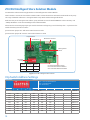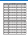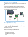
1
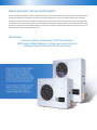
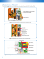
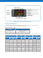
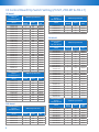
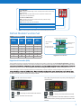
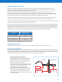
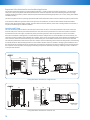
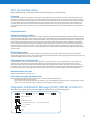
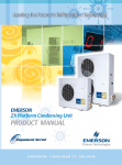
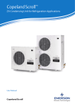
Copeland Scroll TM ZX condensing unit for refrigeration applications User Manual About Emerson Climate Technologies Emerson Climate Technologies, a business segment of Emerson, is the world’s leading provider of heating, air conditioning and refrigeration solutions for residential, industrial and commercial applications. The group combines best-in-class technology with proven engineering, design, distribution, educational and monitoring services to provide customized, integrated climatecontrol solutions for customers worldwide. Emerson Climate Technologies’ innovative solutions, which include industry-leading brands such as Copeland Scroll and White-Rodgers, improve human comfort, safeguard food and protect the environment. For more information, visit EmersonClimateAsia.com. Our Vision Emerson Climate Technologies, With Our Partners, Will Provide Global Solutions To Improve Human Comfort, Safeguard Food And Protect The Environment. Emerson Climate Technologies is pleased to offer the ZX platform refrigeration condensing units (CDU) specifically designed for medium temperature (ZX-MT & ZXB-MT), digital modulated variable capacity medium temperature (ZXD) and low temperature (ZXL-LT) refrigeration. ZX series CDU has been highly successful in the Asian market and enjoys proven success with its energy savings and customerfriendly electronic features. Table of Contents Disclaimer 04 Features and Benefits 04 Nomenclature 05 Bill of Material 05 Physical Layout of the Unit 06 Product Specification Qualified Refrigerants And Oils 07 E2 Control Board - Rotary Switch And Dip Switch Setting (ZX-MT, ZXB-MT & ZXL-LT) 08 Defrost Module Function Set 09 Digital Scroll Controller (ZXD) 09 ZX CDU Intelligent Store Solution Module 10 Installation Condensing Unit Handling 14 Electrical Connection 14 Refrigeration Piping Installation 15 Expansion Valve Selection for Low Ambient Application 16 Location and Fixing 16 Start Up and Operation 17 Diagnostic Initialization Message (ZX-MT, ZXB-MT & ZXL-LT) 17 Diagnostic Messaging - LED Definition (ZX-MT, ZXB-MT & ZXL-LT) 18 Alarm Messaging - Digital Scroll Controller (ZXD) 18 Wiring Diagram 19 Contact Lists 28 ZX Platform CDU Disclaimer Thank you for purchasing the ZX platform condensing unit from Emerson Climate Technologies. ZX platform CDUs are the best in class within the capacity and operating range available in the market. ZX CDU is designed to operate reliably and to deliver high operating efficiencies in medium and low temperature refrigeration applications. It also provides constant monitoring of the compressor operating conditions and displays the running or fault conditions of the CDU. ZX platform CDUs have to be installed by following the industry trade practices for its safe and reliable operation. It is assumed that the CDU is selected, installed and serviced only by professionals. The user manual does not cover good industry practices which are essential on a refrigeration equipment installation. No responsibility can be accepted for damage caused by inexperienced or inadequately trained site technicians or improper installation design. If in doubt, please consult your local sales office, quoting unit model and serial number as shown on each unit nameplate. In case of any ambiguity, the wiring diagram supplied with each unit takes precedence over the diagram in this manual. Introduction to ZX Platform CDU ZX medium temperature, ZXB medium temperature, ZXD digital medium temperature and ZXL low temperature series have been highly successful in the Asian market and enjoys proven success with its energy savings and customer-friendly electronic features. ZX, ZXB, ZXD and ZXL CDUs have been applied by several well known end-users and chain retailers throughout Asia. The ZX platform is also gaining wider acceptance in the global market and specific variants have been developed and exported to the USA and to the European and Middle East markets. Receiving your unit All units are shipped with a holding charge of dry nitrogen inside at a low but positive pressure. Suitable labeling is prominently displayed on both the unit and the packaging. Service connectors are provided on the CDU service valve for the convenient checking of the integrity of the holding charge. Caution! It is very important to check that this holding pressure exists at the time you receive each unit from us or our authorized representatives. Please inform us or our authorized representative if the holding charge is non-existent. Failure to do so could void the claim for other related system faults at a later period. Transit damage is essentially an insurance claim and is not covered under manufacturing defect. It is also advisable to inspect the rest of the unit for obvious physical damage and inform us or our authorized representative in case any is discovered. ZX Platform Condensing Unit was designed based on three factors demanded by industry users: Intelligent Store Solutions - A most innovative approach to enterprise facility management, Emerson’s Intelligent Store™ architecture integrates hardware and services, to provide retailers a single view into their entire network of facilities and understanding what facilities actually cost to operate and maintain. The Intelligent Store architecture transforms data from store equipment and controls into actionable insights. Designed to deliver value in both new and existing stores, Emerson aims to help the retailers: • Make better decisions on recourses investment for greatest impact • Gain accurate feedback and customized service to your specific needs • Reduce operational costs and boost the profitability at most convenience Energy Efficiency - Utilizing Copeland ScrollTM compressor technology, variable speed fan motor, large capacity condenser coil and advanced control algorithms, energy consumption is significantly reduced. End-users can save more than 20% on annual energy costs rather than using hermetic reciprocating units. Reliability - Combining the proven reliability of Copeland ScrollTM compressors with advanced electronics controller and diagnostics, equipment reliability is greatly enhanced. Fault code alerts and fault code retrieval capabilities provide information to help improve speed and accuracy of system diagnostics. Integrated electronics provide protection against over-current, over-heating, incorrect phase rotation, compressor cycling, high pressure resets, low pressure cut-outs. It can also send out a warning message to an operator when there is a liquid floodback, which can prevent critical damage on the unit. 4 Intelligent Store Better Decision Making Highest Efficiency Lower Energy Bills Reliability Lower Maintenance Cost ZXD Family ZX, ZXB and ZXL Family - Capacity modulation to control precise room temperature and humidity Proprietary Electronic Algorithms Present Advantage On Diagnose, Communication, and Protection Purposes. They Are Also Fundamental to Control Fan Speed, Optimizing Energy Performance for Local Seasonal Ambient Temperatures - With real time monitoring of compressor operating conditions Variable Speed Fan Motor and High Efficiency Fan Blade Intelligent Store Built-in ZX Platform Solution Module Controller Oversized Condenser Coil for Maximum Heat Transfer Copeland Scroll Compressor Technology – High Efficiency, Ultra Quiet, High Reliability Base Model F D - 4 5 1 Bill of Material T TF7=380 - 3ph - 60 Hz - TFD = 380V/420V- 3ph- 50 Hz E PFJ = 220V/240V- 1ph- 50 Hz 0 E = Ester Oil O = Mineral Oil 2 1.5 to 7.6 HP L = Low Temp 0 D = Digital Medium Temp B = Medium Temp (R134a) L Blank = Medium Temp Unit Family X TF5 = 200V/230V- 3ph- 60 Hz 200V/220V - 3ph - 50 Hz Figure 1. ZX Platform CDU Features Nomenclature Z • Compressor Reverse Rotation • Compressor Over Current • Compressor Internal Motor Protector Trip • Discharge Gas Over Heat • High Pressure Cut Out • Low Pressure Cut Out (only on MT series) • Refrigerant Flood Back • Compressor Minimum Off Time • Internal Thermal Sensor Failure • Intelligent Store Solution: Communication and Retail Store Monitoring Electrical Code Bill of Material Bill of Material CDU Family BOM Liquid Line Filter Dryer/Sight Glass Oil Separator Accumulator Adjustable LP Switch Fixed LP Switch E2 Controller Digital Scroll Controller Fan Speed Controller Intelligent Store Solution Module Circuit Breaker Sound Jacket Low Ambient Kit Defrost Module Filter Drier ZX ZXB ZXL 401 451 481 401 451 461 ACC ACC ZXD 451 461 471 481 ACC ACC ACC ACC ACC 450 451 461 Note: ACC- Accessory 5 Physical Layout of the Unit The following figures give an introduction to the physical layout of the ZX Platform CDU ZX-MT, ZXB-MT & ZXL-LT E2 Controller ZXD Digital Scroll Controller Scroll Compressor See Fig. 5 for LED and keypad Figure 2. Identifies the Electronic controller assembly on a ZX platform CDU. Accumulator Oil Separator (Optional In MT CDU) Liquid Receiver Liquid Sight Glass/ Moisture Indicator Liquid Filter Drier Suction And Liquid Service Valve Receiver Out Service Valve Compressor Oil Sight Glass Figure 3. Identifies other major components layout on a ZX platform CDU. E2 Power Board Rotary Switch E2 Control Board 3-Bit Dip Switch Power Isolation Switch 2-Bit Dip Switch Defrost Module Compressor Contactor Intelligent Store Solution Module Fuse Holder Electrical Cable connectors Figure 4. Shows the layout of the E2 controller, electrical components, dip switches and rotary switch in the E2 control board. 6 Suction pressure Suction temperature display Program Mode: browses parameter codes or increase value Hot Key Insert : Hot key programming procedure INFO Menu: Press and release it to access INFO Menu Program Mode: below parameter codes or decrease value Maintenance /Clock Enter Alarm Manual Restart Setup Menu Discharge pressure Condenser temperature display Figure 5. Shows LED and keypad of ZXD digital scroll controller. Product Specification For application envelope, envelope varies according to applications and refrigerants. Please refer to ZX platform product catalogue, product manual, or CopelandTM Brand Products Selection Software. Qualified Refrigerants and Oils REFRIGERANT OIL R404A/R507/R134a Emkarate RL 32 3MAF Mobil EAL Artic 22 CC R22 Suniso 3GS Oils are pre-charged in both compressor and oil separator. Total oil volume (liter) for each unit is shown in the table below: ZX Model ZXB BOM Model ZXD BOM ALL Model ZXL BOM ALL Model BOM 401 451 ALL ZXB015E 0.74 ZX0200/E 1.18 1.68 ZXB020E 0.74 ZXL0200/E 1.06 ZX0250/E 1.33 1.83 ZXB025E 0.74 ZXL0250/E 1.06 ZX0300/E 1.33 1.83 ZXB030E 1.36 ZXL0300/E 1.06 ZXB035E 1.36 ZXL0350/E 1.74 ZX0400/E 1.83 2.33 ZXB040E 1.36 ZXD0400/E 1.74 ZXL0400/E 1.74 ZX0500/E 1.83 2.33 ZXB050E 1.89 ZXD0500/E 2.27 ZXL0500/E 1.74 ZXB055E 1.89 ZX0600/E 1.66 2.16 ZXD0600/E 2.27 ZXL0600/E 2.27 ZX0750/E 1.66 2.16 ZXD0750/E 2.27 ZXL0750/E 2.27 ZX0760/E 1.66 2.16 7 E2 Control Board Dip Switch Setting (ZX-MT, ZXB-MT & ZXL-LT) ZX Model Related Software Version 300-0043-02 V2.2 Model With Fan Speed Control Rotary Switch S2 Bit 3 S3 Bit1/ Bit2 Model With Fan Speed Control Rotary Switch S2 Bit 3 S3 Bit1/ Bit2 ZX0200-TFD 1 OFF ON/ON ZXB035E-TFD 5 OFF ON/ON ZX0300-TFD 2 OFF ON/ON ZXB040E-TFD 6 OFF ON/ON ZX0400-TFD 3 OFF ON/ON ZXB050E-TFD 7 OFF ON/ON ZX0500-TFD 4 OFF ON/ON ZXB055E-TFD 8 OFF ON/ON ZX0600-TFD 5 OFF ON/ON ZX0750-TFD 6 OFF ON/ON ZX0760-TFD 6 OFF ON/ON ZX0200-PFJ 7 OFF ON/ON ZX0250-PFJ 8 OFF ON/ON ZX0300-PFJ 9 OFF ON/ON ZX0400-PFJ A OFF OFF/OFF ZX0200-TF5 1 ON ON/ON ZX0300-TF5 2 ON ON/ON ZX0400-TF5 3 ON ON/ON ZX0500-TF5 4 ON OFF/OFF ZX0600-TF5 5 ON OFF/OFF ZX0750-TF5 6 ON OFF/OFF ZX0200-TF7 7 ON ON/ON ZX0300-TF7 8 ON ON/ON ZX0400-TF7 9 ON ON/ON ZX0500-TF7/ ZX0600-TF7 A ON ON/ON ZX0750-TF7 B ON ON/ON Related Software Version 300-0043-03 V2.1 Model ZX0200-TFD 1 S2 Bit 3 OFF Related Software Version 300-0043-00 V2.2 Model Rotary Switch S2 Bit 3 S3 Bit1/ Bit2 ZXL0200-TFD 1 OFF ON/ON ZXL0250-TFD 2 OFF ON/ON ZXL0300-TFD 3 OFF ON/ON ZXL0350-TFD 4 OFF ON/ON ZXL0400-TFD 5 OFF ON/ON ZXL0500-TFD 6 OFF ON/ON ZXL0600-TFD 7 OFF ON/ON 8 OFF ON/ON 1 ON ON/ON ZXL0300-TF5 2 ON ON/ON ZXL0350-TF5 3 ON OFF/OFF ZXL0400-TF5 4 ON OFF/OFF ZXL0500-TF5 5 ON OFF/OFF ZXL0600-TF5 6 ON OFF/OFF ON/ON ZXL0750-TF5 7 ON OFF/OFF ZXL0200-TF7 / ZXL0250-TF7 8 ON ON/ON ZXL0300-TF7 9 ON ON/ON ZXL0350-TF7 A ON ON/ON ZXL0400-TF7 B ON ON/ON ZXL0500-TF7 C ON ON/ON ZXL0600-TF7 / ZXL0750-TF7 D ON ON/ON S3 Bit1/ Bit2 ZX0300-TFD 2 OFF ON/ON ZX0400-TFD 3 OFF ON/ON ZX0500-TFD 4 OFF ON/ON ZX0600-TFD 5 OFF ON/ON ZX0750-TFD 6 OFF ON/ON ZX0200-PFJ 7 OFF ON/ON ZX0250-PFJ 8 OFF ON/ON ZX0300-PFJ 9 OFF ON/ON ZX0400-PFJ A OFF OFF/OFF Related Software Version 300-0043-01 V2.0 Model Related Software Version 300-0043-00 V2.2 With Fan Speed Control ZXL0750-TFD W/O Fan Speed Control Rotary Switch ZXL Model ZXL0200-TF5 / ZXL0250-TF5 ZXB Model 8 Related Software Version 300-0043-00 V2.2 With Fan Speed Control W/O Fan Speed Control Rotary Switch S2 Bit 3 S3 Bit1/ Bit2 ZXL0200-TFD 1 OFF ON/ON ZXL0250-TFD 2 OFF ON/ON ZXL0300-TFD 3 OFF ON/ON ZXL0350-TFD 4 OFF ON/ON Model Rotary Switch S2 Bit 3 S3 Bit1/ Bit2 ZXB015E-TFD 1 OFF ON/ON ZXL0400-TFD 5 OFF ON/ON ZXB020E-TFD 2 OFF ON/ON ZXL0500-TFD 6 OFF ON/ON ZXB025E-TFD 3 OFF ON/ON ZXL0600-TFD 7 OFF ON/ON ZXB030E-TFD 4 OFF ON/ON ZXL0750-TFD 8 OFF ON/ON For ZX-MT Unit: OFF: Evaporator ON/OFF logic is same as compressor and this is the factory default setting ON: Evaporator fan will be ON for all time irrespective of whether the compressor is turned ON or OFF ON 1 2 3 For ZXL-LT & ZXB-MT Units: OFF: SH target value set at 5K and this is the factory default setting for R404A, R134A and R22 ON: SH target value set at 10K, for R407F Not applicable for ZX/ZXL/ZXB units Use setting in the table Note: The settings given in the table are pre-set at the factory for new units Defrost Module Function Set Time of Defrost Time of Defrost Interval Defrost Duration (in Minutes) Rotary Switch1 Time (min) Rotary Switch2 Time (hours) 0 1 2 3 4 5 6 7 0 5 10 15 20 25 30 35 0 1 2 3 4 5 6 7 0 1 2 3 4 5 6 7 Manual Defrost Button Defrost Interval (in Hours) Remote Connector For Manual Defrost E2 Connector Figure 6. Defrost Module Digital Scroll Controller (ZXD) The controller has been pre-programmed with a number of parameter values that are set for typical application. Individual installation requirements, however, may make it necessary to alter parameter settings. The control target of the digital scroll available compressor capacity. The set-point can be altered using the SEtC parameter. Factory setting SEtC is -6oC. The control target of the fan speed controller is to maintain the average condenser mid-coil temperature and hence the the SEtF parameter. Factory setting SEtF is 25oC. Initial setting of set point for saturated suction temperature.Pre-set value is located in the SEtC position as shown in the diagram below: Press for more than 2 seconds Then SEtF (fan speed control set point) will be displayed automatically. SEtC value Flashing or to change set value within 30 seconds press to memorize new set value. SEtC value Flashing Or to change set value within 30 seconds press to memorize new value and Exit, or wait for 30 seconds without pressing any key to memorize value and exit. 9 ZX CDU Intelligent Store Solution Module ZX CDU address is determined using dip switches on the Intelligent Store Solution Module. Switch numbers 1 to 6 set the slave address. Switch number 7 will set the Baud rate and switch number 8 will set the parity. The range of allowable addresses is 1 through 63. Refer to Dip Switch Address Settings table below. Make sure that you are setting the same address, parity and baud rate as in the Dixell XWEB300D. Select “No Parity” and “9.6Kbps Baud Rate” on the ZX CDU Intelligent Store Solution Module. Please note the termination JP3 jumper is just used for the devices at beginning or end of the daisy chain – any devices in the middle of the daisy chain do not need it. JP3 Termination Jumper ON = Add 150 Ω resistor between A and B JP3 Termination Jumper Off = Remove 150 Ω resistor between A and B 7-Segment LEDs Main Board Connector Reset Button Message Recall Button Dip Switch Setting ModBus Connector Connection XWeb E2 Facility Manager D0 RS485+ RS485- D1 RS485- RS485+ JP3 Termination Resistor Jumper ON: Termination Resistor is Enabled OFF: Termination Resistor is Disabled Figure 7. ZX CDU Intelligent Store Solution Dip Switch Address Settings •No. 1 to 6: Set Slave Address •No. 7: Set Baud Rate •No. 8: Set Parity 1 2 3 4 5 6 7 8 Set Address 10 Address OFF OFF OFF OFF OFF ON - - Address=1 OFF OFF OFF OFF ON OFF - - Address=2 OFF OFF OFF OFF ON ON - - Address=3 OFF OFF OFF ON OFF OFF - - Address=4 OFF OFF OFF ON OFF ON - - Address=5 OFF OFF OFF ON ON OFF - - Address=6 OFF OFF OFF ON ON ON - - Address=7 OFF OFF ON OFF OFF OFF - - Address=8 OFF OFF ON OFF OFF ON - - Address=9 1 2 3 4 5 6 7 8 Set Address Address OFF OFF ON OFF ON OFF - - Address=10 OFF OFF ON OFF ON ON - - Address=11 OFF OFF ON ON OFF OFF - - Address=12 OFF OFF ON ON OFF ON - - Address=13 OFF OFF ON ON ON OFF - - Address=14 OFF OFF ON ON ON ON - - Address=15 OFF ON OFF OFF OFF OFF - - Address=16 OFF ON OFF OFF OFF ON - - Address=17 OFF ON OFF OFF ON OFF - - Address=18 OFF ON OFF OFF ON ON - - Address=19 OFF ON OFF ON OFF OFF - - Address=20 OFF ON OFF ON OFF ON - - Address=21 OFF ON OFF ON ON OFF - - Address=22 OFF ON OFF ON ON ON - - Address=23 OFF ON ON OFF OFF OFF - - Address=24 OFF ON ON OFF OFF ON - - Address=25 OFF ON ON OFF ON OFF - - Address=26 OFF ON ON OFF ON ON - - Address=27 OFF ON ON ON OFF OFF - - Address=28 OFF ON ON ON OFF ON - - Address=29 OFF ON ON ON ON OFF - - Address=30 OFF ON ON ON ON ON - - Address=31 ON OFF OFF OFF OFF OFF - - Address=32 ON OFF OFF OFF OFF ON - - Address=33 ON OFF OFF OFF ON OFF - - Address=34 ON OFF OFF OFF ON ON - - Address=35 ON OFF OFF ON OFF OFF - - Address=36 ON OFF OFF ON OFF ON - - Address=37 ON OFF OFF ON ON OFF - - Address=38 ON OFF OFF ON ON ON - - Address=39 ON OFF ON OFF OFF OFF - - Address=40 ON OFF ON OFF OFF ON - - Address=41 ON OFF ON OFF ON OFF - - Address=42 ON OFF ON OFF ON ON - - Address=43 ON OFF ON ON OFF OFF - - Address=44 ON OFF ON ON OFF ON - - Address=45 ON OFF ON ON ON OFF - - Address=46 ON OFF ON ON ON ON - - Address=47 ON ON OFF OFF OFF OFF - - Address=48 ON ON OFF OFF OFF ON - - Address=49 ON ON OFF OFF ON OFF - - Address=50 ON ON OFF OFF ON ON - - Address=51 ON ON OFF ON OFF OFF - - Address=52 ON ON OFF ON OFF ON - - Address=53 ON ON OFF ON ON OFF - - Address=54 ON ON OFF ON ON ON - - Address=55 ON ON ON OFF OFF OFF - - Address=56 ON ON ON OFF OFF ON - - Address=57 11 1 2 3 4 5 6 7 8 Set Address Address ON ON ON OFF ON OFF - - Address=58 ON ON ON OFF ON ON - - Address=59 ON ON ON ON OFF OFF - - Address=60 ON ON ON ON OFF ON - - Address=61 ON ON ON ON ON OFF - - Address=62 ON ON ON ON ON ON - - Address=63 - - - - - - ON - 9.6Kbps - - - - - - - OFF 19.2Kbps - - - - - - ON - Even Parity - - - - - - - OFF No Parity Set Baud Rate Baud Rate Set Parity Parity Network Wiring Dixell XWEB300D Serial Address • • • • • Connect to the ModBUS network using cable with 2 or 3 shielded wires, minimum section 0.5mm2 (e.g. BELDEN8772) Do not connect shield to ground. Do not connect the “Gnd” terminal. Remember to draw a map of the line. This will help you to find an error if something is wrong. RS485 devices are polarity sensitive. Figure 8. Correct Network Wiring Figure 9. Incorrect Network Wiring 12 Termination Resistor for XWEB300D If XWEB300D is placed at the beginning or at the end of the line, please install its termination resistor by adding a jumper in position 2 (JMP2 on the back side of the unit). Do not add the jumper if XWEB300D is placed in the middle of the RS485 line. ZX CDU Connected to XWEB300D ZX CDU connected to the Dixell XWEB300D with the Intelligent Store Solution Module using RS485 ModBUS. Connect the ZX CDU to the ModBUS network as shown in Figure 9. Connect the network cable to the three-terminal connector on the XWEB300D port that has been configured as ModBUS port (COM 12, 13, 14). Connect port “13” of XWEB300D to port “D0” of Intelligent Store Solution Module and port “12” of XWEB300D to port “D1” of Intelligent Store Solution Module for RS485 communication. Intelligent Store Solution Module Dixell XWEB RS485+ Shielded Cable RS485- RS485+ RS485- Main Control Board Figure 10. XWEB300D Connected to the Intelligent Store Solution Module Dixell XWEB300D Configuration XWEB300D is compatible with ZX CDU firmware version 2.1.1 plus patch “Update_CDU-UNITS_(20121203)”. Login into XWEB • Go to Information → Information • Check log update for “Update_CDU-UNITS_(20121203)”. If this is not present, follow the steps below. Open Dixell website http://www.dixell.com/xweb300d-xweb500-xweb500d/eng/, then login (register required) • Go to Support → System sw update → XWEB300D XWEB500 XWEB500D • Download the upgrade package With your web-browser, login into XWEB • Go to Information → System Update menu Provide the XW5 patch file Once file has been selected wait until the upgrade procedure ends (XWEB reboots) Verify the installation ended successfully by checking into the menu • Go to Information → Information for “Update_CDU-UNITS” string Log in again and set up the ZX CDU • Go to Configuration → Devices drop-down menu • Go to Actions → New • Enter device name in the Name field (e.g. ZX CDU) • Select “ZXL-ECT_001” in the Model field • Enter the ModBUS address in the RS 485 address field o Refer to section “Dip Switch Address Settings” • Click New 13 Installation Copeland ZX condensing units are delivered with a holding charge of neutral gas. The condensing unit should be located in such a place to prevent any dirt, plastic bag, leaves or papers from covering the condenser and its fins. The unit must be installed without restricting the airflow. A clogged condenser will increase the condensing temperature, thus reduce the cooling capacity, and lead to a high-pressure switch tripping. Clean the condenser fins on a regular basis. Condensing Unit Handling Transport and Storage Move ZX/ZXB/ZXD/ZXL unit only with appropriate mechanical or handling equipment according to weight. Keep in the upright position. Do not stack single boxes on top of each other without pallet in any case. Keep the packaging dry at all times. Storage 2 Transport ma x 300 Kg 2 1 ma maxx 300 300 Kg Kg 1 Net Weight ZX ZXB ZXD ZXL Model Weight (kg) Model Weight (kg) Model Weight (kg) Model Weight (kg) ZX0200/E 76 ZXB015E 79 ZXD0400/E2 104 ZXL0200/E 79 ZX0250/E 79 ZXB020E 81 ZXD0500/E3 112 ZXL0250/E 81 ZX0300/E 79 ZXB025E 81 ZXD0600/E4 114 ZXL0300/E 81 ZX0400/E1 91 ZXB030E 93 ZXD0750/E5 122 ZXL0350/E 93 ZX0500/E 108 ZXB035E 93 ZXL0400/E 93 ZX0600/E 112 ZXB040E 106 ZXL0500/E 106 ZX0750/E 118 ZXB050E 116 ZXL0600/E 116 ZX0760/E 121 ZXB055E(TBD) 121 ZXL0750/E 121 Notes: 1 100 kg for models under 60 Hz TF5/7 and 50 Hz PFJ 2 109 kg for models under 60 Hz TF7 3 117 kg for models under 60 Hz TF7 4 121 kg for models under 60 Hz TF7 5 127 kg for models under 60 Hz TF7 Electrical Connection Power supply The ZX condensing unit electrical connection to the power supply must be made by qualified technicians, who should refer to the electrical diagrams located inside the electric connection panel. The units are designed for below power supply at ± 10% voltage tolerance. The circuit breaker must be switched off before opening the front panel. Codes HZ Phase Voltages PFJ 50 1 220/240 TFD 50 3 380/420 TF7 60 3 380 TF5 60 3 200/230 Electrical wiring Before commissioning, ensure that neutral “N” wire is connected to the terminal block (“N” furthest to the right). After proper connection of the ZX condensing unit, the control LED on the power board and control board will light. For more details, see wiring diagram in Appendix. Caution! Unit should be powered on at all times except during service. Failure to do so can result in component failure. 14 Refrigeration Piping Installation All interconnecting pipes should be of refrigeration grade, clean, dehydrated and must remain capped at both ends until installation. Even during installation, if the system is left for any reasonable period of time (say two hours), pipes should be recapped to prevent moisture and contaminants from entering the system. Do not assume that the service connection sizes on the unit (at the service valves) are the correct size to run your interconnecting refrigeration pipes. The service valve sizes have been selected for convenience of installation and in some cases (larger units) these may be considered too small. However for the very short pipe run within our units, these service connection sizes are adequate. All interconnecting pipes should be sized to satisfy the duty required. Usually the suction line is insulated, but the liquid line is not. However the liquid line can pick up additional heat from the ambient and adversely affect the sub-cooling desirable for the liquid refrigerant before it enters the expansion valve. The pipe should be sized to ensure optimum performance and good oil return. The sizing must also take into account the full capacity range through which this particular unit will need to operate. Pipe runs should be kept as short as possible, using the minimum number of directional changes. Use large radius bends and avoid trapping of oil and refrigerant. This is particularly important for the suction line. The suction line should ideally slope gently towards the unit. Recommendation slope is 1/200 ~1/250. P traps, double risers and reduced pipe diameters may be required for suction lines where long vertical risers cannot be avoided. All pipes should be adequately supported to prevent sagging which can create oil traps. The recommended pipe clamp support distance is shown in the table. Tube Size Max distance between 2 clamp support 12.7mm (1/2 inch) 1.20 m 16.0mm (5/8 inch) 1.50 m 22.0mm (7/8 inch) 1.85 m 28.5mm (1 1/8 inch) 2.20 m ZXL liquid line insulation ZXL liquid line should be insulated with a 19 mm insulation thickness. Temperature could be as low as –15°C. Brazing recommendations Maintain a flow of oxygen-free nitrogen through the system at a very low pressure during brazing. Nitrogen displaces the air and prevents the formation of copper oxides in the system. If copper oxidization is allowed to form, the copper oxide material can later be swept through the system and block screens such as those protecting capillary tubes, thermal expansion valves, and accumulator oil return holes. This minimizes any entry of contaminants and moisture. • Remove the liquid line connection cap. • Then remove the suction connection cap. • Open both valves midway. Care should be taken to avoid the holding charge from releasing too quickly. • Be sure tube fitting inner diameter and tube outer diameter are clean prior to assembly. • Since both tubes are extended from the condensing unit housing, we recommend insulating the housing by using a wet cloth on the copper tubing. • Recommended brazing materials: a copper / phosphorous or copper / phosphorous / silver alloy rod should be used for joining copper to copper whereas to join dissimilar or ferric metals, use a silver alloy rod, either flux coated or with a separate. • Use a double tip torch. OUTSIDE INSIDE UNIT End of tube During brazing protect housing with damp cloth During brazing pull back fire insulation 15 Expansion Valve Selection for Low Ambient Application For systems expected to operate in varying ambient conditions – namely summer and winter temperatures – the expansion valve (TXV or EXV) sizing should take into consideration the maximum expected saturated condensing temperature at high ambient conditions (summer) and the minimum expected saturated condensing temperature, set at -25°C, during low ambient conditions (winter). The chosen expansion valve’s operating capacities should be well within these limits to ensure satisfactory system performance. In the event that different expansion valves come up for the two conditions, the valve for low ambient condition should be selected. This means that at higher ambient, the valve will be oversized. However, if the valve at the high ambient is selected, it may be too small during low ambient condition. Location and Fixing 1029 500 Power Supply Hole Suction Service Valve Liquid Service Valve 2 Holes 15mm DIA 94 300 70 70 90 23 172 110 840 300 352 388 500 The unit should always be installed in a location that ensures clean air flow. It is recommended that a clearance of 300 mm from the wall (or the next unit) be maintained from the unit’s left and rear panels whereas a clearance of 500 mm must be maintained from the unit’s right, top and front panels (seen facing the front of the unit). Both service access and airflow have been considered in making these recommendations. Where multiple units are to be installed in the same location, the contractor needs to consider each individual case carefully. There can be many variations of unit quantities and available space and it is not the intention of this manual to go over these. Ideally, the unit should be mounted on a solid concrete slab with anti-vibration pads between unit feet and concrete. However the ZX condensing unit has also been designed for wall mounting on suitable brackets. Wall mounting brackets are not included. Another factor to consider in finding a good installation site is the direction of the prevailing wind. For example if the air leaving the condenser faces the prevailing wind, the air flow through the condenser can be impeded, causing high condensing temperatures ultimately resulting in reducing unit life. A baffle is a remedy for this situation. 2-R7.5MM GROOVE 580 424 500 Single Fan Unit 2 to 4 HP 500 Fixing dimensions and distances - Single fan unit 500 1029 352 300 2 Holes 15mm DIA 23 300 70 70 110 388 94 2-R7.5MM GROOVE 90 172 1242 Power Supply Hole Suction Service Valve Liquid Service Valve 500 424 Fixing dimensions and distances - Dual fan unit 16 580 Dual Fan Unit 4 to 7.6 HP Start Up and Operation Before commissioning, ensure that all valves on the condensing unit are fully opened. Evacuation The evacuation procedure is based upon achieving an actual system vacuum standard and is not time dependent. Before the installation is put into commission, it has to be evacuated with a vacuum pump. Proper evacuation reduces residual moisture to 50ppm. The installation of adequately sized access valves at the furthest point from the compressor in the suction and liquid lines is advisable. To achieve undisturbed operation, the compressor valves are closed and the system is evacuated down to 0.3 mbar / 0.225 Torr. Pressure must be measured using a vacuum pressure (Torr) gauge on the access valves and not on the vacuum pump; this serves to avoid incorrect measurements resulting from the pressure gradient along the connecting lines to the pump. Charging Procedure Refrigerant charging procedure The scroll compressor design requires system charging as quickly as possible with liquid refrigerant into the liquid line. This will avoid running the compressor under conditions where there is insufficient suction gas. Sufficient suction gas is available to cool not only the motor but also the scrolls. Temperature builds up very quickly in the scrolls if this is not done. Do not charge vapor (gas) refrigerant into the ZX Scroll unit. The suction service valve must not be fully closed at any time while the compressor is running. To do so would cause damage to the compressor in the same manner as explained above. This valve is provided for ease of connection and for the fitting of service gauges without removing the unit panel. It is recommended to charge the ZX unit with refrigerant via its service valves. It is recommended to break the vacuum in the system with a partial charge of the refrigerant, before starting the system. For charge adjustment, it is recommended to check the liquid sight glass just before the expansion valve. Oil charging procedure Emerson ZX condensing units are supplied only with a compressor oil charge. After commissioning, the oil level should be checked and topped up if necessary. The oil level should be approximately halfway up the sight glass (ZXL/ZXD units). Oil can be charged through the Schraeder valve on suction valve. Scroll compressor rotation direction Scroll compressors, like several other types of compressors, will only compress in one rotational direction. The direction of rotation is not an issue with single-phase compressors since they will always start and run in the proper direction. Threephase compressors will rotate in either direction depending upon the phasing of the power. Since there is a 50-50 chance of connecting power in such a way that causes rotation in the reverse direction, it is important to include notices and instructions in appropriate locations on the equipment to ensure proper rotation direction when the system is installed and operated. Maximum compressor cycle Maximum permitted starts per hour is 10. Check before starting & during operation Both valves should be fully opened on the liquid line, in order to prevent trapping liquid. • Check that all valves are fully opened. • After starting and operation conditions are stabilized, it is recommended to check the oil level in compressor(s) and see if there is a need to add oil to ensure a sufficient oil level (halfway up the sight glass). Diagnostic Initialization Message (ZX-MT, ZXB-MT and ZXL-LT) When the unit is initially powered on, the diagnostic module will show the following signals. (1 second)- > (3 seconds)- > (3 seconds)-> - Software Version No. - Unit Identification Code “F”-With OD Fan Speed Control; “-”- W/O OD Fan Speed Control “-” ZX; “L” ZXB & ZXL - Power On LED 2 LED 1 17 Diagnostic Messaging - LED Definition (ZX-MT, ZXB-MT and ZXL-LT) LED1-Unit Status Display Controller Pause Unit Automatic Reset LED2-Error/Warning Code Status Display Display Warning Signal Error/Warning Idle (Stop When Reach To Set-point) No error/warning Run Compressor Phase Error (Wrong Phase Sequence/Loss of Phase) Every Protection Action About To Start 1 Compressor Inside Thermal Protector Trip Every Protection Action Controller Lock Unit Manual Reset Every Protection Action NA NA NA <5 times Protection In 1 Hour ZX: <3 times Protection In 1 Hour ZXL: Every Protection <5 times Protection In 1 Hour Every Protection <5 times Protection In 1 Hour 6th Protection In 1 Hour Defrost Compressor Over Current Every Protection Action Stop Due to Error Overheat Every Protection Action Lockout Compressor High Pressure Cut Out Every Protection Action Compressor Low Pressure Cut Out 2 Every Protection Action DLT Thermistors Failure Every Protection Action Ambient Temperature Sensor Failure Every Protection Action NA NA Mid-coil Temperature Sensor Failure Every Protection Action NA NA PHE Vapor In Temperature Sensor Failure or Over Range 3 ZX: <4th Protection In 1 Hour ZXL: NA 6th Protection In 1 Hour NA NA Every Protection Action NA NA PHE Vapor Out Temperature Sensor Failure or Over Range 3 Every Protection Action NA NA System Liquid Flood Back Warning ~20% Liquid Back NA NA Notes: 1 New start, normal start by program and any start request delay 2 “LP Cutout”signal is not applicable in ZXL condensing unit. 3 PHE Vapor In/Out temperature sensor is not applicable in ZX medium temperature condensing unit. Alarm Messaging - Digital Scroll Controller (ZXD) Alarm Mode Set Points Controller Actions Reset Remarks dLt DLT >= dLt after dLd time delay - Compressors are turned off Auto reset when DLT < dLt-dLH DLT E01L Low pressure is lower than ELP (Level 3 Parameter) - Compressors are turned off - Fans are unchanged Auto reset when LP >= ELP(Level 3) LP Auto reset when Number of activations < PEn in PEi time LP E0L Mechanical LP switch opens - Compressors are turned off - Fans are unchanged Manual reset when Number of activations >= PEn in PEi time key for 3 sec or - Press - Turn off and on the unit C-LA LP < LAL - Signaling only Auto reset when LP = LAL + delta (0.3bar) LP C-HA LP >= HAL - Signaling only Auto reset when LP = HAL -delta (0.3bar) LP - Compressors are turned off - Fans are turned on Auto reset when Number of activations < PEn in PEi time Manual reset when Number of activations >= PEn in PEi time E0H Mechanical HP switch opens - Press key for 3 sec or - Turn off and on the unit HP HP F-HA HP >= HAF - HFC = yes, compressor are turned off Auto reset when HAF + delta (0.3bar) Cond Mid Temp. P1 Suction Transducer failure or out of range - Compressors are activated according to SPr or PoPr Auto reset when probe is normal LP P2 Condenser Mid Coil Sensor failure or out of range - Fans are activated according to FPr Auto reset when probe is normal Cond Mid Temp. P3 Discharge Temp Sensor failure or out of range -The functions related to No.3 probe are disabled Auto reset when probe is normal DLT DLT: Discharge line temperature LP: Low pressure HP: High pressure 18 LP 19 ATTENTION: Unit MUST be grounded! PFJ: 220V-50 Hz -1Ph ZX/ZXL Condensing Unit Wiring Diagram ZX/ZXL/ZXB Condensing Unit Wiring Diagram For BOM 481 TFD - 380/420V - 50Hz - 3Ph TF7 - 380V - 60Hz - 3Ph 20 21 TFD: 380/420V - 50Hz - 3Ph TF7: 380V - 60Hz - 3Ph ZX/ZXL Condensing Unit Wiring Diagram TF5: 220/230V - 50Hz/60Hz - 3Ph ZX/ZXL Condensing Unit Wiring Diagram 22 23 ATTENTION: Unit MUST be grounded! R22 TFD: 380V/420V - 50Hz - 3Ph (With Fan Speed Control Function) ZXD Condensing Unit Wiring Diagram Black White Capacitor1 White Black E Blue U 1 2 L1 3 4 W 5 6 N N Black T1 Blue Fuse (2A/250V) T2 T3 Black Yellow Red Red Red 22N/C A2 Contactor T1(U) 2 Internal motor protector T3(W) COMP'R Crankcase Heater T2(V) Yellow L2 Red L3 Blue Aux 21N/C Black A1 1 V ZXD Condensing Unit Wiring Diagram M1 M2 12 Capacitor2 White White 10 Circuit Breaker "I" (With Fan Speed Control Function) E E 3 R22 TF7: 380V-60Hz-3Ph 1 22 23 24 Fan Speed Controller 15 16 Input: 230VAC Terminal Block Transformer ATTENTION:Unit MUST be grounded! COND. Mid Coil Temp. Sensor LP Switch White Pressure Transducer Brown Notes: 1. Dashed line " " is wired by installer. 2. The connector-jumper(#16 & #17) must be removed when the cold start connection is necessary. Compressor DLT Sensor Blue Out 0~10V 4~20mA + 23 24 4 6 16 18 20 15 17 19 Hot KeY / TTL Digital Scroll Controller 8 10 12 14 Pb3 Pb1Pb2 LP Id3 Id1 3 5 7 9 11 13 + 2 1 21 22 - Inj.Solenoid Valve Blue ALARM LIGHT Blue + HP HP Switch - + i2F 25 26 27 28 - PWM Valve 1 2 3 4 5 6 7 8 9 10 11 12 13 14 15 N N N N 16 17 Output: 12VAC Cold Start Connection Case Temp Thermostat Or Liquid Line Switch 24 25 1 E E 3 White 10 15 16 22 23 24 12 Capacitor2 White Black White Capacitor1 White Black Fan Speed Controller M2 M1 R404A TF7: 380V-60Hz-3Ph E L1 L2 L3 2 1 2 Internal motor protector T3(W) COMP'R T1(U) Red Yellow Red Red Blue Black Crankcase Heater T2(V) A2 22N/C T1 T2 T3 Black N N Fuse (2A/250V) 6 Contactor 4 5 3 1 Blue Aux 21N/C Black A1 Red Blue Yellow Circuit Breaker "I" W V U (With Fan Speed Control Function) Input: 230VAC ZXD Condensing Unit Wiring Diagram Transformer Terminal Block ATTENTION:Unit MUST be grounded! COND. Mid Coil Temp. Sensor LP Switch Brown White Pressure Transducer Output: 12VAC - 2 1 23 24 + 4 6 Hot KeY / TTL 16 18 20 15 17 19 Digital Scroll Controller 8 10 12 14 Pb3Pb1Pb2 LP Id3 Id1 3 5 7 9 11 13 21 22 + Out 0~10V 4~20mA + HP - + i2F PWM Valve HP Switch 25 26 27 28 - Blue Blue ALARM LIGHT 1 2 3 4 5 6 7 8 9 10 11 12 13 14 15 N N N N 16 17 Blue Compressor DLT Sensor Notes: 1. Dashed line " " is wired by installer. 2. The connector-jumper(#16 & #17) must be removed when the cold start connection is necessary. Case Temp Thermostat Or Liquid Line Switch Cold Start Connection ZXD Condensing Unit Wiring Diagram (Without Fan Speed Control Function) TFD: 380V/420V-50Hz-3Ph ATTENTION: Unit MUST be grounded! 26 General Information Technical data are correct at the time of printing. Updates may occur, and should you need confirmation of a specific value, please contact Emerson Climate Technologies stating clearly the information required. Emerson Climate Technologies cannot be held responsible for errors in capacities, dimensions, etc., stated herein. Products, specifications, and data in this literature are subject to change without notice. The information given herein is based on data and tests which Emerson Climate Technologies believes to be reliable and which are in accordance with today’s technical knowledge. It is intended for use by persons having the appropriate technical knowledge and skill, at their own discretion and risk. Our products are designed and adapted for fixed locations. For mobile applications, failures may occur. The suitability for this has to be assured from the plant manufacturer, which may include making appropriate tests. Note: The components listed in this catalogue are not released for use with caustic, poisonous or flammable substances. Emerson Climate Technologies cannot be held responsible for any damage caused by using these substances. 27 Contact Lists Emerson Climate Technologies Suite No. 2503-8, 25/F, Exchange Tower, 33 Wang Chiu Road, Kowloon Bay, Kowloon, Hong Kong Tel: (852) 2866 3108 Fax: (852) 2520 6227 Australia Emerson Climate Technologies Australia Pty Ltd 356 Chisholm Road Auburn NSW 2144, Australia Tel: (612) 9795 2800 Fax: (612) 9738 1699 China - Beijing Emerson Climate Technologies (Suzhou) Co. Ltd Room 1017 JianWei Building, 66 Nan Lishi Road, XiCheng District, Beijing, PRC Tel: (8610) 5763 0488 Fax: (8610) 5763 0499 China - Guangzhou Emerson Climate Technologies (Suzhou) Co. Ltd 508-509 R&F Yinglong Plaza, No. 76 Huangpu Road West, Guangzhou, PRC Tel: (8620) 2886 7668 Fax: (8620) 2886 7622 China - Shanghai Emerson Climate Technologies (Suzhou) Co. Ltd 1801 Building B, New CaoHeJing International Business Center, 391Guiping Rd, Shanghai, PRC Tel: (8621) 3418 3968 EmersonClimateAsia.com Asia 02 A01 10 – R01 Issued 08/2014 – GSCAA001 Emers ©2014 Emerson Climate Technologies, Inc. All rights reserved. India - Mumbai Emerson Climate Technologies (India) Ltd Delphi B-Wing, 601-602, 6th Floor Central Avenue, Hiranandani Business Park, Powai, Mumbai 400076 Tel: (9122) 2500 6630 / 2500 6632 Fax: (9122) 2500 6570 India - PUNE Emerson Climate Technologies (India) Ltd Plot No. 23, Rajiv Gandhi Infotech Park, Phase - II, Hinjewadi, Pune 411 057, Maharashtra, India Tel: (9120) 2553 4988 Fax: (9120) 2553 6350 Indonesia PT Emerson Indonesia Wisma 46 - Kota BNI, 16th Floor, Suite 16.01, Jl. Jend.Sudirman Kav.1. Jakarta 10220, Indonesia Tel: (6221) 2513003 Fax: (6221) 2510622 Japan Emerson Japan Ltd Shin-yokohama Tosho Building No. 3-9-5 Shin-Yokohama, Kohoku-ku Yokohama 222-0033 Japan Tel: (8145) 475 6371 Fax: (8145) 475 3565 Malaysia Middle East & Africa Emerson Climate Technologies PO Box 26382 Jebel Ali Free Zone – South Dubai, UAE Tel: (9714) 811 8100 Fax: (9714) 886 5465 Philippines Emerson Climate Technologies 23rd Floor San Miguel Properties Centre #7 St. Francis Street, Ortigas Center, Mandaluyong City, Philippines Tel: (632) 689 7200 South Korea Emerson Electric Korea Ltd. 3F POBA Gangnam Tower, 119 NonhyunDong, Gangnam-Gu, Seoul 135-010 Korea Tel: (822) 3483 1500 Fax: (822) 592 7883 Taiwan Emerson Electric (Taiwan) Co. Ltd 3F No. 2 DunHua South Road Sec.1, Taipei (105), Taiwan Tel: (8862) 8161 7688 Fax: (8862) 81617614 Thailand - Bangkok Emerson Electric (Thailand) Ltd 34th Floor, TCIF Tower, 1858/133, Bangna Trad, Bangkok 10260, Thailand Tel: (662) 716 4700 Fax: (662) 751 4241 Emerson Electric (Malaysia) Sdn. Bhd. Level M2, Blk A, Menara PKNS-PJ Jalan Yong Shook Lin 46050 Petaling Jaya, Selangor, Malaysia Tel: (603) 7949 9222 Fax: (603) 7949 9333 Vietnam Emerson Climate Technologies - Vietnam Suite 307-308, 123 Truong Dinh St., Dist.3 Ho Chi Minh, Vietnam Tel: (84) 908 009 189