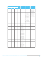
1
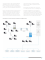
RealSens is certified by the South African National Regulator for Compulsory Standards (NRCS)
1
CONTENTS
PAGE
1.
About RealSens™
2.
RealSens™ system architecture
4.
RealSens™ communication technology
5.
RealSens™ system components
6.
Attributes of the RealSens™ system
7.
RealSens™ technical specifications
13.
Installing the RealSens™ system
17.
Operation and maintenance of the RealSens™ system
18.
Associated products
19.
Certifications (CE, ISO, SABS, NRCS, etc.)
20.
Safety & Environmental Precautions
ABOUT REALSENS™
RealSens™ is an Advanced Metering Infrastructure
(AMI) system. It is a robust metering, communication
and control system turning utility distribution
infrastructure into “smart grids” by integration of
remote meter data with conventional back-office
systems via a cloud-based database. This is achieved
through its high-tech, low-cost data acquisition and
secure communication capabilities which is based on
a bi-directional, license-free, ultra-low-power, radio
frequency mesh network, integrated with GSM, Fiber
Optic or WI-FI networks. Meter readings with intervals
as frequent as 1 minute (normal settings: ½-hourly,
hourly or daily), read on demand, time of use (TOU)
and active leak monitoring are but a few features of
RealSens™. Add to this the ability to control devices
in the field from the comfort of your office, as well as
accessing your own data on the Internet, and you own
a true AMI system.
RealSens™ was developed to meet the specific
demands of water utilities, which are generally more
onerous than the technological and operational
demands of electricity utilities, where power and
communications are readily available at the meter.
The demands of water utilities resulted in a specific
technology choice and product design, to deliver a
long-life battery operated system, independent of an
external power supply source, incorporating a built-in
communication system that is low cost, yet robust and
reliable, even in the harshest environmental conditions.
By meeting these demands, RealSens™ can be classed
as a fully multi–utility system whether it is water, gas,
electricity, or renewables.
RealSens™ now offers smart grid capability at lower
cost than first generation walk-by and drive-by
technologies. RealSens™ delivers truly intelligent,
remote metering and control capabilities that can be
utilised for: infrastructure management; load shedding;
customer services; regulatory reporting; credit
management; time-of-use reports; flow logging;
utility demand management; distributed generation
and a multitude of infrastructure and business
planning functions that older or lesser technologies
cannot deliver.
Under certain circumstances it is necessary to
commence a metering automation process with a
walk-by drive-by (WBDB) system, for example such
as when meters are not simultaneously available
in a dense and contigious geographical area, for
connection to a remote metering system. For situations
like this, RealSens™ is available as a super-efficient
WBDB system, in which the need for complicated and
expensive route planning software is not required. This
WBDB mode of RealSens™ can easily be transformed
into a fixed mesh network system when the density of
meters connected to the RealSens™ system justifies it.
The capabilities of RealSens™ make it an automatic
choice as a tool for resource demand management.
Data previously not available to utility managers is now
a push of a button away for prompt decision making,
reporting, billing and planning. RealSens™, unlike
many other systems, actually utilizes the bi-directional
communication capability, in a similar way that SCADA
(supervisory control and data acquisition) systems do.
This true bi-directional communication capability and
proven reliability under harsh environmental conditions,
make RealSens™ the leader in low-cost “smart grid”
solutions, also for water utilities.
RealSens™ was developed over the past decade by
paying careful consideration to customers’ needs.
A multi-disciplinary team of specialists from the
fields of water and power utilities, electronics &
radio communications, software development, data
management and business process design, responded
to these needs, and following extensive technology
research and field trials, the system was released. The
same team is still listening and responding to the
customers’ needs, which provides RealSens™ with its
futuristic capabilities.
RealSens™ is distributed worldwide by Reonet.
RealSens is certified by the South African National Regulator for Compulsory Standards (NRCS)
1
REALSENS™ SYSTEM ARCHITECTURE
First Generation AMR
The first step towards intelligent metering was driven
by the need to improve the numerous shortcomings
in the traditional approach to utility meter reading.
The difficulties associated with access to meters,
occupational health and safety (OHS) issues,
inaccuracies inherent in manual meter reading,
the need for special reads and the cost associated
therewith, begged for the development of a more
efficient system.
The first generation intelligent metering technologies
were designed to overcome these specific difficulties,
which led to the development of walk-by and drive-by
systems to supply one reading per meter per month,
just like the manual reading system.
Walk-by and Drive-by (WBDB) Metering Systems
In WBDB systems, meter readings are retrieved
through a Radio Frequency transceiver, usually in the
434, 868 or 915 MHz ISM (industrial, scientific and
medical) frequency bandwidths, which sends metering
information wirelessly to a handheld unit while the
meter reader walks down the road. The RF transceiver
at the meter is usually of a “sealed for life” construction
and can be used in above or below ground
applications. Other variations such as the Touchpad
System are also still employed at a smaller scale.
Drive-by systems allow for more rapid meter reading
than walk-by systems, resulting in a more efficient
solution for meter reading and billing. Utilising a
similar meter and transceiver installation set-up as
with walk-by, the drive-by system incorporates a more
powerful vehicle-based data collection transceiver.
Meter reading software normally includes a route
management program, creating a route for the meter
reading vehicle to follow.
Later versions of WBDB systems can log meter
readings at much smaller time intervals (e.g. ½-hourly)
but is still only transmitted to a handheld receiver
when it downloads the data from close proximity. The
2
RealSens™ version of WBDB does not require route
planning software because it automatically links the
meter GPS co-ordinates to a unique radio address,
which in turn is assigned to the meter interface unit
(MIU), the meter serial number and associated meter,
property and consumer details.
Second Generation AMR
Second generation intelligent metering technologies
make it possible to receive meter readings directly from
the meter on an office computer, eliminating any walkor drive-by. This is achieved by installing fixed radio
networks or wired communication systems, with the
ability to upload meter readings at pre-programmed
intervals to data concentrators from where the readings
are forwarded to management systems. These
systems are characterised by one-way communication
capability making read-on-demand impossible. The
communication media used for these systems include
power line carrier with mixed success, optic fibre, radio
and GSM data transmission.
Third Generation: AMR to AMI
The third generation intelligent metering was born out
of recognition of the need for two-way communication
with utility meters, to obtain special reads on demand
and to perform limited control functions on utility
devices. These systems are referred to as Advanced
Metering Infrastructure (AMI) systems. The two-way
communication systems used for AMI systems also
include power line frequency modulation, optic
fibres, radio and GSM data transmission, although
the effective utilization of two-way communication for
large scale deployments remains a challenge for most
system developers.
Fourth Generation:
AMI to RealSens™
Smart Grids transcend meter reading as it has been
understood before. Smart Grids refer to utility
distribution infrastructure that is equipped with
meters, devices, communication infrastructure and
Data Sheet: Advanced Metering Infrastructure System
management systems, which render the distribution
grid intelligent. This is achieved by providing realtime or near-real-time information, automatically or
on demand, to utility managers, for the management,
planning and control of the distribution infrastructure.
The term smart grid was initially coined for electricity
distribution infrastructure. It specifically implies the
capability to manage the load profile of the grid to
better manage exception conditions. Smart grids
also provide powerful and rich information for grid
expansion planning, statutory reporting, operational
improvement planning, increasing operational
efficiencies and it offers a comprehensive suite of
customer services.
Smart Grids for water utilities were, until recently,
not a viable proposition, from a cost, reliability, and
technology availability point of view. RealSens™
now offers cost-effective smart grid capabilities, by
integrating radio and GSM technology, and it exploits
the full bi-directional communication potential of this
systems architecture. A powerful cloud-based database
adds the final touches to a highly advanced system.
The RealSens™ system architecture is depicted in the figure below.
RealSens is certified by the South African National Regulator for Compulsory Standards (NRCS)
3
REALSENS™ COMMUNICATION TECHNOLOGY
At present, four categories of communication
technologies dominate the AMR/AMI/smart metering/
smart grid space. The technologies are closely linked
to the functionality of the system, for example, walkby and drive-by systems employ short-range radio
frequency technologies, whereas more modern AMR,
AMI and smart grids are based on integrated radio
frequency (RF) mesh networks, long-range fixed RF
networks or hard-wired communication systems.
RF fixed mesh network
RealSens™ employs the technology of an RF
fixed (mesh) network that connects to pervasive
communication systems such as GSM/GPRS through
the RealSens™ RF/GSM Gateway device. Unlike
long-range, star-configured fixed networks, RF mesh
networks employ ultra-low-power two-way transceivers
operating on shorter range, licence-free RF bands
within the ranges 433MHz, 868MHz or 915MHz, also
known as the industrial, scientific and medical (ISM)
frequency bands. RealSens™ operates in the 868MHz
bandwidth. It provides all the functionality to operate as
an AMI system, but at lower cost than long-range fixed
networks, and it overcomes some limitations of the
long-range, star-configured fixed radio networks. For
example, integrated RF mesh networks do not require
pre-licensing or operational licensing. It also does
not pose any health hazards due to electromagnetic
emissions, thanks to the ultra-low power output. The
RealSens™ communication protocols eliminate the
risk of data loss. Some of the communication protocols
include frequency-hopping and smart listening and
identification algorithms.
RF walk-by,
drive-by (WBDB) system
RealSens™ can also be implemented as a walk-by,
drive-by (WBDB) system. In this implementation,
only the RealSens™ meter interface units (MIUs) are
required to be installed. The WBDB system can later
be expanded into a fixed mesh network simply by
adding RealSens™ Repeaters and RealSens™ Gateway
devices. The RealSens™ WBDB implementation
does not require route-planning software because it
automatically links the meter’s GPS co-ordinates to a
unique radio address, which in turn is assigned to the
MIU, the meter serial number and associated meter,
property and consumer details. Meter readings are
collected by a handheld portable device running the
RealSens™ Sync software.
Computer screen
image of typical F/N topology
4
Data Sheet: Advanced Metering Infrastructure System
REALSENS™ SYSTEM COMPONENTS
The RealSens™ RF system connects to meters or endpoint devices. The metering data is transmitted to a
cloud-based database from where the data is available
for back-office systems that produce information and
drive processes.
RealSens™ communicates with most utility meters and
devices, provided they are equipped with an output
interface. It is fully compatible with contact closure reed
probes, electronic or inductive pulse emitters or an
industry-standard 4-20 mA output.
The first and very important part of the system is the
meter and its data output capability to which the
RealSens™ transceiver is connected. In order to
ensure that RealSens™ is connected to meters and
sensors that are of adequate quality and compatibility,
a field audit process precedes the RealSens™
installation process.
To streamline and standardise the quality and
effectiveness of the audit process, the RealSens™ team
developed productivity- and quality-management
software, which also supports system configuration
and meter reading synchronisation. The RealSens™
Sync software, which was developed as an aid in this
process, is also used in the WBDB implementation of
RealSens™ to collect meter-reading data. This
software can be installed on most Windows mobile
handheld devices.
RealSens™ Meter Interface Units (RS-MIU) connect
by data cable to the meter output interface. Each
MIU can accommodate up to four channels, allowing
four meters to be connected to one MIU. RS-MIUs are
housed in half-spherical enclosures that are rugged and
waterproof to IP68 standard.
The RealSens™ Repeaters (RS-Repeater) operate as
range extenders and are designed so that they can be
strapped to lampposts or fixed to flat vertical walls.
The long battery life and rugged construction makes
the RS-Repeater a maintenance-free installation and its
small profile renders it unobtrusive.
The RealSens™ GSM Gateway (RS-Gateway) acts as
a router between the RF mesh network and the GSM
network. The Gateway unit can “wake up” the selected
MIU and communication path components, from which
data can be requested on demand. The RS-Gateway
is housed in a rugged outdoors enclosure. It requires
an external power source, which could include solar
power, and it is optionally equipped with a standby
battery that will operate the unit independently in case
of mains power failure.
RealSens™ Manager (RS-Manager) is a powerful
software suite that remotely configures and manages
the entire radio mesh network. RS-Manager continually
monitors the RealSens™ system behaviour and it
automatically reports any system problems, such
as signal strength, “no reads” at scheduled times,
tampering, leaks on consumer properties, or any other
anomalous behaviour. RS-Manager automatically
manages downloads at preset intervals.
The RealSens™ GSM Gateway transfers data to a
cloud-based database (RS-DB) by establishing a direct
connection to the server through an access point name
(APN) via GSM/GPRS. Once connection is established
to our cloud server, data is transferred using the
RealSens™ server, which will then store each reading
in the database. This data can be either exported or
imported to other systems through various file formats,
e.g. Excel, CSV, ASCII, Text or direct database access.
These systems can be meter data management
systems (MDMSs), billing systems, reporting systems,
geographical views in Google Earth™, network
management systems, geographic information systems
(GISs) in Google Earth™, maintenance systems or
consumer information systems (CISs).
RealSens is certified by the South African National Regulator for Compulsory Standards (NRCS)
5
ATTRIBUTES OF THE REALSENS™ SYSTEM
• RealSens™ is highly suitable for connection to
existing metering infrastructure that contains a large
variety of meters of different sizes, types and ages,
from different manufacturers
• RealSens™ is proven to withstand the harsh outdoor
environmental conditions at water utilities, where it
has been subjected to rigorous field tests
• It offers smart grid capabilities for all utilities, at a
lower cost than most drive-by AMR systems
• It is capable of measuring water, gas,
electricity, temperature and any industry standard
4-20mA signal
• The four-channel RS-MIUs increase costeffectiveness. A mains-powered 16-channel MIU is
under development. This would be a cost-effective
technology to connect to a large number of
electricity meters in close proximity (meter box) and
will be able to stream data for control purposes
• The system is entirely driven through user-friendly
interface applications (web-based or workstationbased), linked directly to a cloud-based database
• RealSens™ uses the proprietary global utility
management protocol (GUMP)
• RealSens™ MIUs, Repeaters and Gateway
geographical locations and signal strength can be
viewed with Google Earth™
• RealSens™ provides for leak reporting at
consumer meters, based on customisable
“leak thresholds”
• It has an easy, secure web-based user interface for
viewing meter readings and for report creation
• RealSens Sync can be used for pre-installation
planning and post-installation quality control,
through field audits or by providing real-time
meter index comparison capabilities
• RealSens™ is as suitable for multi-utility submetering in buildings as it is for remote rural utilities
or very large urban utilities
• RealSens™ is highly scalable and is well suited to a
phased implementation
The bi-directional communication capability of
RealSens™ allows it, amongst other things, to:
• Instruct individually selected MIUs to log
consumption data at different sample rates
• Obtain “special reads” in real time
• Remotely configure and maintain the integrated
RF mesh network and remotely synchronise meter
readings with the metering database
• Close or open circuit breakers, or shut and open
valves – thereby allowing a remote credit-control
capability, either as prepaid or credit meter
• Remotely control entire utility networks
through closing and opening circuit breakers
or isolating valves
6
RealSens Meter Data Management
and Web-based Reporting System
Data Sheet: Advanced Metering Infrastructure System
REALSENS™ TECHNICAL SPECIFICATIONS
General system specifications
• Designed for reliability, simplified low-cost
installation, ultra-low power usage and robustness
• Remote configuration and system operation
from friendly user-interfaces and cloud-based
database server
• Ultra low power and “long-range” wireless
technology with significant power advantages over
other systems
• Real-time bi-directional communication capability,
allowing for the control of endpoint devices
• Easy network/device setup using GIS technologies
that can be carried out remotely
• RealSens™ does not restrict the number of
endpoints that can be connected within a
mesh network
• Long battery life with local life monitoring (>10 years
– normal operation)
• Narrow band RF communications
• Operates in 868 MHz ISM frequency (major
worldwide license free frequency)
• The mesh network can accommodate up to 5
repeater hops
• ETS300-220, FCC part 15 compliance
(certification ready)
• RF power output 32 mW, +15 dBm for
individual devices
• Programmable output power from 0 dBm to +15
dBm (32 mW) (5 dBm steps)
• Automatic Frequency Error Correction
• Sensitivity control can be manually set
• Adaptive Frequency Hopping
• Continuous phase 2-level FSK modulation
using Frequency Hopping Spread Spectrum
(FHSS) techniques
• Receiver standby algorithms to reduce
power consumption
• Various security algorithms available on request
• Quality of service management
• Fast RSSI detection (Received Signal Strength
Indicator) provides signal strength for both directions
of data communication at each hop
MIU connected to meter
• Fully managed data packet routing algorithms
allowing identification of failed segments of
backbone, etc
• Frequency switching at various positions on the
RF Mesh network to avoid unnecessary waking up of
unneeded devices, thus ensuring longer battery life
• Large number of deployment / installation tools such
as automatic network configuration, based on GIS
and live signal strength analysis
RealSens is certified by the South African National Regulator for Compulsory Standards (NRCS)
7
RS-Pulse specification
The RS-Pulse is an ultra low powered electronic
switch that replaces less reliable mechanical reed
switches. RS-Pulse makes use of electronic Hall Effect
technology.
• Produces an accurate pulse count output through
intrinsic hysteresis that eliminates switch bounce
• Suitable for connecting to most magnetic
pulse meters
• More robust (less prone to damage during
installation and operations)
• Accuracy not impaired by vibration and
temperature fluctuations
• Sensor housing is equipped with interlocking
guide to ensure optimal positioning for
accurate pulse pickup
Pulse sensor and MIU
Data connector nodes for RS232 output
RS-Pulse Hall-effect pulse pick-up sensor
8
Data Sheet: Advanced Metering Infrastructure System
RS-MIU specification
The RS-MIU is a small, battery operated, radio
transceiver designed to be situated at the meter
and accept the pulse input from any AMR compliant
meter. Its function is to locally track and record the
consumption pulses, as well as monitor leak and
tamper conditions.
• Monitors up to 4 pulse inputs
• Tracks the index readings on a continuous basis
• Records and stores up to 720 index readings (FIFO
data logging) for later downloading. Data logging
takes place at specific times and intervals that are
configurable, enabling a snapshot look that allows
for accurate consumption balancing calculations
• Monitors consumption on an hourly basis and flags
the presence of a residual leak conditions
• Detects cable cut conditions
• Provides diagnostic functions by means of 2
pushbuttons and 4 LEDs
• Robust, attractive, low-profile IP68 rated
water-proof enclosure
• Replaceable batteries (>10 yrs lifespan under normal
operating conditions)
• Withstand 600kg vertically induced load
• No data loss when radio network goes down
• 868 MHz ISM frequency band
RS-MIU with top screwed on (left) and off (right),
showing PC board with RF antenna and
diagnostics buttons
RS-MIU underside, showing four-channel data cables
RS-MIU component schematic diagram
RealSens is certified by the South African National Regulator for Compulsory Standards (NRCS)
9
MIU Data with connectors
MIU Base with PC Board
10
Data Sheet: Advanced Metering Infrastructure System
RS-Repeater specifications
RS-Gateway specifications
The RS-Repeater is a battery-operated small radio
transceiver, the purpose of which is to extend the mesh
network range.
The RS-Gateway is essentially a router that connects
the RF mesh network to the GPRS/GSM network.
• Robust IP68 sealed housing, designed to be
attached to a building or strapped to a pole
• Replaceable battery (>10 years lifespan under normal
operating conditions)
• 868MHz ISM frequency band
RS-Repeater, showing fixing lugs for
strapping or screwing fasteners
• Powered by mains power or solar panel
• Manages SIM card and PIN code functions
• Automatically maintains connection to the GPRS/
GSM network
• Maintains an open connection to the RS-Server
• Monitors network status through a
“heartbeat” system
• Provides diagnostic information by means of an
onboard LCD display
• 868MHz ISM frequency band
RS-Gateway GSM unit showing RF and
GSM antennas
RS-Gateway GSM unit showing RF and GSM antennas
RealSens is certified by the South African National Regulator for Compulsory Standards (NRCS)
11
RealSens™ Sync specifications
RealSens™ Sync is the software that provides the walkby, drive-by (WBDB) meter-reading capabilities of the
RealSens™ system. RealSens™ RealSens™ Sync also
assists with the installation and maintenance of the
RealSens™ system.
• Runs on Windows Mobile 5 or later
• Provides all WBDB download functionality
• Establishes secure bi-directional communication with
nearby MIUs
• Reads and validates meter index
• Checks strength of radio signal
• Checks and corrects pulse weight of meter
pulse output
• Synchronises MIU with meter reading
• Performs system diagnostics
• Provides system configuration tools
• 868MHz ISM frequency band
RS-Manager specifications
RS-Manager is the software that drives the
RealSens™ system. It provides the tools for:
•
•
•
•
Setup and configuration of devices on the network
Management of the RealSens™ system
Diagnostics and utilities
Collection of meter-reading data and insertion into
the cloud database
• Database management
• Importing and processing WBDB meter-reading data
from RealSens™ Sync
RS-Sync software on PDA
Weights and sizes
Weights and dimensions of RealSens™ components:
Dimension and weight
12
Component
RS-Probe
RS-MIU
RS-Repeater
RS-Gateway
Weight (gm)
10
430
198
200
Length (mm)
47
-
-
-
Width (mm)
-
-
38
24
Height (mm)
-
48
269
99
Diameter (mm)
5
100
-
-
Data Sheet: Advanced Metering Infrastructure System
INSTALLING THE REALSENS™ SYSTEM
With RS-Sync, field auditors can verify the quality
and other parameters of the installed meters, the
correctness of the installation, and the compatibility of
the signal output facility to be connected to RealSens™
transceivers. The audit process team can also provide
independent advice to utility managers regarding the
field-tested performance of utility meters. The utility
company or its contractors should first replace and/
or reinstall all meters and devices that were found to
be of inadequate standard, quality or compatibility, or
incorrectly installed.
RealSens™ can be installed as either an RF F/N mesh
system or as an advanced WBDB system. Installation
procedures for the Meter Interface Units (MIUs) are
exactly the same for the RF F/N mesh system and the
WBDB system. The installation of the RF F/N mesh
system will be discussed below.
A comprehensive RealSens™ User Manual (RSUM) has
been developed for installers, operators, maintenance
staff and data management staff, for the effective
installation and management of the RealSens™
system. An RSUM is available for all clients who wish to
install and manage their own RealSens™ system. The
RealSens™ system is otherwise installed, operated and
maintained by licensed implementers such as Reonet.
The licensed implementers can also provide a suite
of utility management services and solutions that
are underpinned by the RealSens™ AMR system.
These services and solutions include:
1. Meter data management services
2. Automated web-based utility billing
3. Automated web-based utility reporting
Meter audits
• The suitability of the installed meter (is it AMR
compatible, is it of good quality and accuracy, is
it correctly installed, is it serving the correct
consumer, etc.)
• The communication modules of the meter (this
determines the type of data connection (pulse
or data), the pulse weight, no. of outputs, units of
measure, tariff applicable, etc.
• The locality of the meter (GPS co-ordinates, property
Surveyor General details), accessibility
• Meter details (size, manufacturer, model, serial
number, meter reading, current transformer sizes –
if applicable, circuit breaker sizes, programmable
meter, meter ownership, etc.)
All of the above-mentioned data, captured during
the meter audit phase, is imported into the RSManager system.
RS-MIU installation
The RS-MIU can be installed indoors, outdoors (below
or above ground), inside housings containing the
meter, or inside meter chambers with a concrete lid.
The RS-MIU can have up to four channels with cables
up to three metres long. Each channel can connect
to meters either by hardwiring into a meter’s output
terminals, or to a pulse pickup (inserted or attached).
When the RS-MIU is installed, all relevant data pertinent
to that installation is captured on the handheld device
loaded with the installation software. This includes
data such as RS-MIU unique radio address, unique
meter number, GPS co-ordinates and pulse weight.
Synchronisation of the actual meter reading to the
RS-MIU occurs at the final stage when the system
is configured.
Prior to installation of the RealSens™ system, it is
necessary to conduct a meter audit, the purpose of
which is to determine the following:
RealSens is certified by the South African National Regulator for Compulsory Standards (NRCS)
13
Variable (determine on site)
132mm dia. hole augered
through concrete/asphalt
Steel lid
110mm dia. PVC pipe
with screw-on endcap
Concrete/
Asphalt
20mm dia. hole drilled
and fitted with 15mm
dia. PVC duct
Polystyrene
Sand
MIU
Data Cable threaded
through duct
110mm dia. PVC sleeve slotted into auger hole
Above and below: typical below-ground (meter well)
installation of an RS-MIU inside a sealed 110-diameter
PVC pipe with thermal insulation
R
n
e a
l S e
s
s
n
e a
l S e
s
R
R
n
e a
l S e
14
Data Sheet: Advanced Metering Infrastructure System
RS-Repeater installation
The RS-Repeater is a range extender and an RF mesh
network-building component. RS-Repeaters should
be installed at high points in the network area, so
as to offer the best transmission capability for signal
coverage. RS-Repeaters are commonly attached to
lamp posts, telephone poles and flag poles or affixed
to buildings.
RS-Gateway installation
The RS-Gateway is the device that connects the RF
mesh network to the GSM network, in other words, the
RS-Gateway acts as a GSM-RF router. RS-Gateways are
connected to a 12V DC – 1.5 Amp power supply. RSGateways should always be installed indoors, but when
it has to be installed outdoors it should be enclosed
in a water-resistant enclosure with an IP rating of at
least 65.
Water (F/N and WBDB) installation
All relevant information about the meter, data channel,
MIU, radio address, GPS co-ordinates, property
description, etc, should be captured through a job
card system in order to ensure that the relevant data is
imported into and maintained by RS-Manager and RSDB. A predetermined list of fields must be captured on
the job card system, in order for the fixed network to be
built. This information can later be used for fault finding
and troubleshooting. A post-installation audit must
be undertaken within a day to a week after installation
(timing dependent on the size and consumption of the
meter) to ensure that the meter readings as reflected
in RS-Manager, correctly tracks with the meter readings
on the face of the meter.
In order to install a RealSens™ MIU on a water meter,
information about the meter is required. The meter
manufacturer, model, size and type will dictate the
type of pulse pickup to be used with the meter.
Pulse pickups can either be supplied by the meter
manufacturer (HRI Mei, HRI, RD01, Actaris Cybels)
or from RealSens™. The RealSens™ pulse pickup
(RealSens™ Probe) is a solid hall-effect sensor (no
moving parts) and is available for most mainline
meters. In some instances a computer and software are
required for programming the meter manufacturer’s
pulse pickups.
The pulse pickup is connected to the RS-MIU in
accordance with the applicable manufacturer’s
connection diagram. Placement of the RS-MIU must
be determined before it is connected, so as to limit
exposure to vandalism or the accidental damage of
cabling and the RS-MIU. Once the RS-MIU is installed,
its screw-on lid needs to be removed and the unit
needs to be switched on. The RS-MIU is now ready to
be synchronised with the reading of the meter to which
it is connected. It is important to note the pulse weight
of the different meters or pulse pickups, as this will
ensure that the ongoing meter reading values on the
RS-MIU and RS-Manager are correct.
Examples of typical pulse pick-up
connections to domestic-sized water meters
RealSens is certified by the South African National Regulator for Compulsory Standards (NRCS)
15
Electricity (F/N &
WBDB) installation
For electricity meters, the RS-MIU data cable can be
connected directly to the meter’s output interface.
Furthermore, if it is a programmable meter, the meter
would need to be re-programmed with a meter scheme
set-up, using the meter manufacturer`s proprietary
software. Some meters need modifications done on the
electronic board, in order for the RS-MIU to receive the
output pulse.
The remainder of the installation procedures is
essentially the same as for water meters.
Network building
and configuring (F/N)
Once the relevant data from the job card fields have
been inserted into RS-Manager, the RS-MIU positions
are plotted on a Google Earth™ background. With
the aid of the Google Earth™ tool, the RF technician
employs his knowledge of the site to set up the RF
fixed mesh network topology.
In this scheme, the RS-Gateway is placed as close as
possible to the geographical centre of the installed
RS-Repeaters and RS-MIU’s. A sufficient number of
RS-Repeaters must be installed in close enough
proximity to MIU’s to ensure that adequate signal
strength is maintained between the devices. It is
important to note that only five repeater hops are
available before the signal must enter the RS-Gateway.
A predefined list of fields must be captured on the job
card system in order for the fixed network to be built.
All RS-MIUs and RS-Repeaters are thereafter ready
for configuration on the network. A data SIM card,
supplied by a cellphone provider, must be inserted into
the RS-Gateway and then activated, whereafter it is
provisioned on an APN network.
The RF power and sensitivity settings as well as a few
other parameters must be set to ensure optimum
communication. It also includes the synchronisation of
the actual meter reading with the RS-MIU, in order for
the meter reading values in RS-Base to be the same as
those reflected on the face of the meter.
Operation and maintenance of the RealSens™ system
RealSens™ is operated differently when used as an RF
F/N mesh system as opposed to when it is used as a
WBDB system. The comprehensive RealSens™ User
Manual (RSUM) describes how RealSens™ should be
installed and operated in the two different modes. A
short summary is provided below.
Schematic diagram of the RealSens™
components in a fixed mesh network
configuration showing five repeater hops
16
Data Sheet: Advanced Metering Infrastructure System
OPERATION AND MAINTENCE
OF THE REALSENS™ SYSTEM
Operation and maintenance – F/N
RS-Sync software on a handheld mobile computing
device or personal digital assistant (PDA) is used
for many operational and maintenance functions.
Before RS-Sync can be used on site for operation
and maintenance, the latest zone lookup file must be
uploaded to the PDA.
Using the RS-Sync software, the following should
be done daily:
Check the “Collection attempt” column for
communication failures. After six collection-attempt
failures, a forced download on that device must be
triggered to confirm if there is a communication error.
On a weekly basis it is neccassery to conduct a
forced download (using RS-Sync) on all MIUs. This
will download the necessary data records to provide
a snapshot of the network communications and will
identify devices that are not functioning properly at
that moment.
Using data from the actions described above, a
maintenance list of work orders can be produced
for maintenance teams to investigate and remedy
communication errors.
Operation and
maintenance – WBDB
RS-Sync software on a PDA is used for many
operational and maintenance functions. Before RS-Sync
can be used on site for operation and maintenance, the
latest zone lookup file must be uploaded to the PDA.
Meter readers use RS-Sync, loaded onto their PDAs,
to download meter readings from the MIUs connected
to the meters. When in close proximity to the meters
and MIUs (from 10m to 200m), the PDA automatically
establishes RF connection and downloads the meter
reading data. RS-Sync needs to be set to “Download”
and the GPS must be “ON”. If certain MIU downloads
fail, the meter reader can force a retry to reread and
download the data records. If the MIU fails again, a
work order needs to be generated for such events
and devices to be investigated and remedied. When
the meter reading route is complete, or all MIUs have
been downloaded, the file with all the data records are
imported into RS-DB using RS-Manager.
Maintenance procedures for both F/N and WBDB,
regarding the MIUs, are the same, but F/N will also
include RS-Repeater and RS-Gateway repairs.
RealSens is certified by the South African National Regulator for Compulsory Standards (NRCS)
17
ASSOCIATED PRODUCTS
RealSensTM Meter Data Management
and Web-based Reporting System
GSM data logger with external antennae
Model MD-AP RealSensTM Metering
Model CM-1 RealSensTM Metering
Model PD-AP RealSensTM Metering
18
Model PD-A RealSensTM Metering
Data Sheet: Advanced Metering Infrastructure System
CERTIFICATIONS
RealSens™ device components are manufactured
by ISO 9001, ISO 14000 or ISO 18000 registered
companies.
RealSens™ devices are assembled in accordance with
ISO 9001, ISO 14000 and ISO 18 000 standards.
RealSens™ devices emit electromagnetic pulses in the
RF licence-free frequency of 868MHz in compliance
with ETS300-220, FCC part 15 and the European
Conference of Postal and Telecommunication
Administration (CEPT) Electronic Communications
Committee (ECC) Regulation document ERC/REC
70-03 for short-range devices (SRD), Annex 3 for Local
Area Networks.
Certification documents are available on request.
RealSens™ is already certified by the South African
National Regulator for Compulsory Specifications
(NRCS) to accurately download water consumption
readings from the following types of meters: Itron
Model Aquadis+; Sensus Model 220C; Elster Kent
Model PSM and Elster Kent Model KSM.
System certification can be procured on demand for a
large number of other meter types and sizes.
RealSens is certified by the South African National Regulator for Compulsory Standards (NRCS)
19
SAFETY AND ENVIRONMENTAL PRECAUTIONS
Number
1
Aspect
Activity/ Product/
Service
Impact
Significance - Normal Conditions
Significance - Abnormal Conditions
Severity
Frequency
Rating
Severity
Frequency
Rating
Health impact
0
1
0
-
-
-
0
1
0
-
-
-
Resource depletion
1
-
198
-
-
-
Resource depletion
1
-
-
-
-
-
Battery replacement
Hazardous
3
-
38
-
-
-
/ product
substances - Health
decommissioning of
& environment
Landfill pollution
1
-
269
-
-
-
1
-
-
-
-
-
Electromagnetic
Short-range,
RF Emissions
small data packet
transmission, once
daily, between ultra
low-powered (32 mW)
RF transceivers in
868MHz bandwidth
2
Electromagnetic
Short-range,
Interference with
RF Emissionst
small data packet
other RF systems
transmission, once
daily, between ultra
low-powered (32 mW)
RF transceivers in
868MHz bandwidth.
3
Electricity usage
Battery-powered RF
transceiver devices
(RS-MIU and RSRepeater) - entire
manufacturing process
4
Electricity usage
Mains-powered
RS-Gateway - entire
manufacturing process
+ operational use
- small data packet
transmission, once
daily, over existing
GSM networks
5
Product disposal
RF transceiver devices
once every 10 years
6
Product disposal
Packaging disposal packaging in plastic
bubble wrap and
cardboard boxes of RF
transceiver devices for
transport and storage
until installation and
commissioning.
7
Fuel
Transport of small,
Fuel consumption,
consumption
light-weight, RF
Resource depletion
transmission devices
(maximum weight
per device = 200g,
aggregate weight =
450g, minimum weight
= 430g)
20
Data Sheet: Advanced Metering Infrastructure System
Significance - Emergency Conditions
Severity
Frequency
Rating
-
-
-
Risk
Operational
Law & Regulation
0
None required
ETS300-220, FCC
Compliant. ISM
part 15
bandwidths below
Rating
Procedure
Reference
Comments
prescribed power
output limits
(32mW for 868MHz)
-
-
-
0
None required
European
Compliant. ISM
Conference
bandwidths below
of Postal and
prescribed power
Telecommunication
output limits
Administration
(32mW for 868MHz)
(CEPT) Electronic
Communications
Committee
(ECC) Regulation
document ERC/
REC 70-03 for
Short-range devices
(SRD), Annex 3 for
Local Area Network
-
-
-
1
Energy-efficient
South Africa
production
processes
-
-
-
1
Energy-efficient
South Africa & UK
production
processes
-
-
-
3
Re-use packaging
UK
materials. Obviate
the need for
foil packagin
by switching off
RS-MIU’s and
removing batteries
from RS-Repeaters
during transport
and storage, in
order to prevent
battery run-down
due to accidental
RF activation
-
-
-
3
End-user business
UK
process
-
-
-
1
Logistics
International
companies
business
processes. Timely
orders and buffer
stock to limit air
transport
RealSens is certified by the South African National Regulator for Compulsory Standards (NRCS)
21
Contact details
SOUTH AFRICA
UNITED KINGDOM
Unit 45
Thembi Place Office Park
Calderwood Road
Lonehill
Johannesburg
South Africa
1010 Cambourne Business Park
Cambourne
Cambridge
CB23 6DP
United Kingdom
Reonet (Pty) Ltd
Tel.: +27 11 706 4564
Fax: +27 11 706 2662
Email: [email protected]
22
Reonet UK Ltd
Email: [email protected]
Data Sheet: Advanced Metering Infrastructure System