1
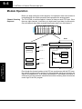
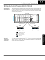
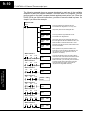
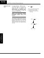
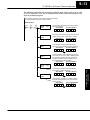
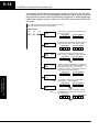
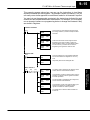
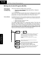
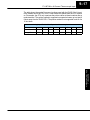
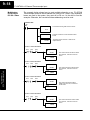
F3–08THM–n
8-Channel
Thermocouple Input
In This Chapter. . . .
Ċ Introduction
Ċ Module Specifications
Ċ Setting the Module Switches
Ċ Connecting the Field Wiring
Ċ Module Operation
Ċ Writing the Control Program
19
9–2
F3–08THM–n 8-Channel Thermocouple Input
Introduction
Automatic
Conversion
The F3–08THM–n Thermocouple Input Module provides eight, differential
thermocouple input channels (12-bit resolution). The module automatically converts
type E, J, K, R, S or T thermocouple signals into direct temperature readings. No
extra scaling or complex conversion is required. You can select between _F or _C
operation.
This module is also available in versions specially designed to convert millivolt signal
levels into direct digital values (0–4095). Two versions are available, one for
0–50mV and one for 0–100mV.
Hardware Features The F3–08THM–n also features automatic cold junction compensation,
thermocouple linearization, plus analog and digital filtering. The temperature
calculation and linerazation are based on data provided by the National Bureau of
Standards.
F3–08THM–n
8Ch. Thermocouple In.
Diagnostic
Features
Thermocouple burnout and other errors are automatically reported to the CPU. For
example, if the thermocouple becomes disconnected, then a value of 4095 is
assigned to that channel.
9–3
F3–08THM–n 8-Channel Thermocouple Input
Module Specifications
The following table provides the specifications for the F3–08THM–n Thermocouple
Input Module from FACTS Engineering. Review these specifications to make sure
the module meets your application requirements.
8, differential inputs
Input Ranges
Type E: –270/1000 _C, –450/1832 _F
Type J: –210/760 _C, –350/1390 _F
Type K: –270/1370 _C, –450/2500 _F
Type R: 0/1768 _C, –32/3214 _F
Type S: 0/1768 _C, –32/3214 _F
Type T: –270/400 _C, –450/752 _F
–1: 0 – 50 mV
–2: 0–100 mV
Resolution
12 bit (1 in 4096)
Input Impedance
27KW DC
Absolute Maximum Ratings
Fault protected input, 130 Vrms or 100 VDC
Cold Junction Compensation
Automatic
Conversion Time
15ms per channel, minimum
1 channel per CPU scan
Converter Type
Successive Approximation, 574
Linearity Error
"1 count (0.03% of full scale) maximum
Maximum Inaccuracy at 77 °F
(25 °C)
0.35% of full scale
Accuracy vs. Temperature
57 ppm / _C maximum full scale
Power Budget Requirement
50 mA @ 9 VDC, 34 mA @ 24 VDC
External Power Supply
None required
Operating Temperature
32° to 140° F (0° to 60° C)
Storage Temperature
–4° to 158° F (–20° to 70° C)
Relative Humidity
5 to 95% (non-condensing)
Environmental air
No corrosive gases permitted
Vibration
MIL STD 810C 514.2
Shock
MIL STD 810C 516.2
Noise Immunity
NEMA ICS3–304
The F3–08THM–n Thermocouple Input appears as a 16-point module. The module
can be installed in any slot configured for 16 points. See the DL305 User Manual for
details on using 16 point modules in DL305 systems. The limitation on the number of
analog modules are:
S For local and expansion systems, the available power budget and
16-point module usage are the limiting factors.
F3–08THM–n
8Ch. Thermocouple In.
Analog Input
Configuration
Requirements
Number of Channels
9–4
F3–08THM–n 8-Channel Thermocouple Input
Setting the Module Jumpers
Jumper Locations
The module is set at the factory for _C thermocouple readings. If this is acceptable
you do not have to change any of the jumpers. The following diagram shows how the
jumpers are set.
WARNING: DO NOT change the calibration jumper settings. If you think this
jumper has been changed, make sure it is NOT in the CAL position. All
calibration is performed at the factory. Any changes to this may affect the
module accuracy which could result in the risk of personal injury and/or
equipment damage.
Selecting _F or _C
Operation
There is a jumper located on the bottom
of the board that selects between _C and
_F temperature measurements. This
jumper (labeled _F) should be removed if
you require _C measurements.
Measurement
Selection
_F
CNTS
Remove this jumper
for _C operation.
F3–08THM–n
8Ch. Thermocouple In.
Selecting 0–4095
Operation
There is a jumper located on the bottom
of the board that allows you to disable the
direct temperature conversion feature. If
you install a jumper on the CNTS pin, the
temperature will be represented by a
digital value between 0 and 4095. For
example, an E type thermocouple would
have a value of 0 for –450 _F and a value
of 4095 for 1832 _F.
NOTE: If you are using the –1 (50mV) or
the –2 (100mV) millivolt input versions,
you should make sure this jumper is
installed.
Measurement
Selection
_F
CNTS
Install this jumper to obtain
digital values (0 – 4095).
9–5
F3–08THM–n 8-Channel Thermocouple Input
Connecting the Field Wiring
Wiring Guidelines
Your company may have guidelines for wiring and cable installation. If so, you should
check those before you begin the installation. Here are some general things to
consider.
S Use the shortest wiring route whenever possible.
S Use shielded wiring and ground the shield at the signal source. Do not
ground the shield at both the module and the source.
S Don’t run the signal wiring next to large motors, high current switches, or
transformers. This may cause noise problems.
S Route the wiring through an approved cable housing to minimize the risk
of accidental damage. Check local and national codes to choose the
correct method for your application.
User Power Supply The F3–08THM–n receives all power from the base. A separate power supply is not
required.
Requirements
Wiring Diagram
Note 1: Terminate shields at the respective signal source
Note 2: Leave unused channels open (no connection)
Internal Module Wiring
THERMOCOUPLE
F3–08THM
A/D
See note
C
C
–1
–1
CH1
+1
+1
–2
–2
Examples of differential
Thermocouple wiring
+2
+2
CH3
+3
+3
C
C
–4
–4
+4
+4
–5
+5
C
–6
CH6
+6
–7
Examples of grounded
Thermocouple wiring
+7
–8
CH8
+8
C
Analog
Switch
–5
+5
C
–6
+6
–7
+7
–8
+8
C
F3–08THM–n
8Ch. Thermocouple In.
–3
–3
9–6
F3–08THM–n 8-Channel Thermocouple Input
Module Operation
Channel Scanning
Sequence
Before you begin writing the control program, it is important to take a few minutes to
understand how the module processes and represents the analog signals.
The F3–08THM–n module supplies1 channel of data per each CPU scan. Since
there are eight channels, it can take up to eight scans to get data for all channels.
Once all channels have been scanned the process starts over with channel 1.
Scan
I/O Update
Channel 1
Scan N
Execute Application Program
Channel 2
Scan N+1
Channel 8
Scan N+7
Channel 1
Scan N+8
F3–08THM–n
8Ch. Thermocouple In.
.
.
.
Read the data
.
.
.
Store data
Even though the channel updates to the CPU are synchronous with the CPU scan,
the module asynchronously monitors the thermocouple signal and converts the
signal to a temperature (or 12-bit binary) representation. This enables the module to
continuously provide accurate measurements without slowing down the discrete
control logic in the RLL program.
9–7
F3–08THM–n 8-Channel Thermocouple Input
Understanding the You may recall the F3–08THM–n module appears to the CPU as a 16-point module.
These 16 points provide:
I/O Assignments
S an indication of which channel is active.
S the digital representation of the temperature.
Since all I/O points are automatically mapped into Register (R) memory, it is very
easy to determine the location of the data word that will be assigned to the module.
F3–08THM
8pt
Relay
8pt
Output
8pt
Output
050
–
057
040
–
047
030
–
037
16pt
Input
8ch
(Analog)
020
027
–
120
127
R 002, R012
010
017
–
110
117
16pt
Input
000
007
–
100
107
R 000, R010
R 011
MSB
1
1
7
R 001
LSB
MSB
1
1
0
LSB
0
1
0
0
1
7
Within these two register locations, the individual bits represent specific information
about the analog signal.
The next to last three bits of the upper
Register indicate the active channel. The
indicators automatically increment with
each CPU scan.
Active Channel
Scan
Inputs
Channel
N
000
1
N+1
001
2
N+2
010
3
N+3
011
4
N+4
100
5
N+5
101
6
N+6
110
7
N+7
111
8
N+8
000
1
R011
MSB
LSB
1 1 1 1 1 1 1 1
1 1 1 1 1 1 1 1
7 6 5 4 3 2 1 0
- active channel
indicator inputs
F3–08THM–n
8Ch. Thermocouple In.
Active Channel
Indicator Inputs
9–8
F3–08THM–n 8-Channel Thermocouple Input
Temperature Sign
Bit
The most significant bit is used to note
the sign of the temperature. If this bit is
on, then the temperature is negative. If
the bit is off, then the temperature is
positive.
R011
MSB
LSB
1 1 1 1 1 1 1 1
1 1 1 1 1 1 1 1
7 6 5 4 3 2 1 0
- temperature sign
Analog Data Bits
Temperature Input
Resolution
F3–08THM–n
8Ch. Thermocouple In.
Millivolt Input
Resolution
The first twelve bits represent the
temperature. If you have selected the
0–4095 scale, the following format is
used.
Bit
Value
Bit
Value
0 (LSB)
1
6
64
1
2
7
128
2
4
8
256
3
8
9
512
4
16
10
1024
5
32
11
2048
R011
R001
MSB
LSB
1 1 1 1 11 1 1
1 1 1 1 11 1 1
7 6 5 4 32 1 0
0 0 0 0 0 0 0 0
1 1 1 1 1 1 1 1
7 6 5 4 3 2 1 0
- data bits
Typically, the F3–08THM–n resolution enables you to detect a 1 _C change in
temperature. The National Bureau of Standards publishes conversion tables that
show how each temperature corresponds to an equivalent signal level.
Since the module has 12-bit resolution,
the analog signal is converted into 4096
“pieces” ranging from 0 – 4095 (212). For
example, with a –2 (100mV) module a
signal of 0 mV would be 0, and a signal of
100 mV would be 4095. This is
equivalent to a a binary value of 0000
0000 0000 to 1111 1111 1111, or 000 to
FFF hexadecimal. The diagram shows
how this relates to the example signal
range.
Each “piece” can also be expressed in
terms of the signal level by using the
equation shown. The following table
shows the smallest signal levels that will
result in a change in the data value for
each signal range.
Range
0–100 mV Scale
100mV
0 mV
0
4095
Resolution + H * L
4095
H = high limit of the signal range
L = low limit of the signal range
Highest Signal
Lowest Signal
Smallest Change
0 – 50 mV
50 mV
0 mV
12.2 mV
0 – 100 mV
100mA
0mA
24.2 mV
Now that you understand how the module and CPU work together to gather and
store the information, you’re ready to write the control program.
9–9
F3–08THM–n 8-Channel Thermocouple Input
Writing the Control Program (DL330 / DL340)
Identifying the
Data Locations
Since all channels are multiplexed into a single data word, the control program must
be setup to determine which channel is being read. Since the module provides input
points to the CPU, it is very easy to use the channel status bits to determine which
channel is being monitored.
F3–08THM
8pt
Relay
8pt
Output
8pt
Output
050
–
057
040
–
047
030
–
037
16pt
Input
020
027
–
120
127
R 002, R012
8ch
(Analog)
010
017
–
110
117
16pt
Input
000
007
–
100
107
R 000, R010
R 011
MSB
R 001
LSB
1 1 1 1
1 1 1 1
7 6 5 4
1
1
0
MSB
0
1
7
LSB
0
1
0
- temperature sign
Automatic
Temperature
Conversion
If you are using the temperature scale (°F or° C) then you do not have to perform any
scaling. Once you convert the binary temperature reading to a four-digit BCD
number, you have the temperature.
F3–08THM–n
8Ch. Thermocouple In.
- active channel
indicator inputs
- data bits
9–10
F3–08THM–n 8-Channel Thermocouple Input
The following example shows a program designed to read any of the available
channels of data into Register locations. Once the data is in a Register, you can
perform math on the data, compare the data against preset values, etc. Since the
DL305 CPUs use 8-bit word instructions, you have to move the data in pieces. It’s
simple if you follow the example.
Read the data
374
Store channel 1
114
115
116
F3–08THM–n
8Ch. Thermocouple In.
Store channel 2
114
115
116
Store channel 3
114
115
116
Store channel 4
114
115
116
Store channel 5
114
115
116
Store channel 6
114
115
116
Store channel 7
114
115
116
Store channel 8
114
115
116
DSTR3
R011
F53
This rung loads the four data bits into the
accumulator from Register 011 on every scan.
DOUT1
R501
F61
Temporarily store the bits to Register 501.
DSTR1
R001
F51
This rung loads the eight data bits into the
accumulator from Register 001.
DOUT1
R500
F61
Temporarily store the bits to Register 500. Since
the most significant bits were loaded into 501, now
R500 and R501 contain all twelve bits in order.
DSTR
R500
F50
Now that all the bits are stored, load all twelve bits
into the accumulator.
BCD
F86
DOUT
R400
F60
DOUT
R402
F60
DOUT
R404
F60
DOUT
R406
F60
DOUT
R410
F60
DOUT
R412
F60
DOUT
R414
F60
DOUT
R416
F60
Math operations are performed in BCD. This
instruction converts the binary data to BCD. (You
can omit this step if your application does not
require the conversion.)
The channel selection inputs are used to let the
CPU know which channel has been loaded into the
accumulator. By using these inputs to control a
DOUT instruction, you can easily move the data to
a storage register. Notice the DOUT instruction
stores the data in two bytes. (Two bytes are
required for four digit BCD numbers.)
9–11
F3–08THM–n 8-Channel Thermocouple Input
Using the Sign Bit
By adding a couple of simple rungs you can easily monitor the temperature for
positive vs. negative readings. (For example, you have to know whether the
temperature is +100 _F or –100 _F.) Notice how we’ve changed Channel 2 to control
an output that denotes the sign of the temperature.
Read the data
374
Store channel 1
114
115
116
Store channel 2
114
115
116
114
115
116
DSTR3
R011
F53
This rung loads the four data bits into the
accumulator from Register 011 on every scan.
DOUT1
R501
F61
Temporarily store the bits to Register 501.
DSTR1
R001
F51
This rung loads the eight data bits into the
accumulator from Register 001.
DOUT1
R500
F61
Temporarily store the bits to Register 500. Since
the most significant bits were loaded into 501, now
R500 and R501 contain all twelve bits in order.
DSTR
R500
F50
Now that all the bits are stored, load all twelve bits
into the accumulator.
BCD
F86
DOUT
R400
F60
DOUT
R402
F60
117
200
114
115
116
117
200
RST
Store channel 3
114
115
116
Store channel 4
114
115
116
DOUT
R404
F60
DOUT
R406
F60
The channel selection inputs are used to let the
CPU know which channel has been loaded into the
accumulator. By using these inputs to control a
DOUT instruction, you can easily move the data to
a storage register. Notice the DOUT instruction
stores the data in two bytes. (Two bytes are
required for four digit BCD numbers.)
If 117 is on, then the temperature on channel 2 is
negative.
If 117 is off, then the temperature on channel 2 is
positive.
F3–08THM–n
8Ch. Thermocouple In.
SET
Math operations are performed in BCD. This
instruction converts the binary data to BCD. (You
can omit this step if your application does not
require the conversion.)
9–12
F3–08THM–n 8-Channel Thermocouple Input
Scaling the Input
Data
If you are using the –1 (50mV) or the
–2 (100mV) versions, you may want to
scale the data to represent the
measurements in engineering units,
which provide more meaningful data.
This is accomplished by using the
conversion formula shown.
Units +
A S
4096
Units = value in Engineering Units
A = Analog value (0 – 4095)
S = high limit of the Engineering
unit range
NOTE: The thermocouple versions
automatically provide the correct
temperature readings. Scaling is not
required.
The following example shows how you
would use the analog data to represent
pressure (PSI) from 0 to 100. This
example assumes the analog value is
1760. This should yield approximately
42.9 PSI.
Units +
A S
4096
Units + 1760 100
4096
F3–08THM–n
8Ch. Thermocouple In.
Units + 42.9
9–13
F3–08THM–n 8-Channel Thermocouple Input
The following instructions are required to scale the data. (We’ll continue to use the
42.9 PSI example.) Once we’ve explained how these instructions operate, we’ll
show an example program.
This example assumes you have already read the analog data
and stored the BCD equivalent in R400 and R401
Scale the data
114
115
116
DSTR
R400
F50
This instruction brings the analog value (in BCD)
into the accumulator.
Accumulator
Aux. Accumulator
1 7 6 0
0 0 0 0
R577
DIV
K4096
F74
The analog value is divided by the resolution of the
module, which is 4096. (1760 / 4096 = 0.4296)
Accumulator
Aux. Accumulator
0 0 0 0
4 2 9 6
R577
DSTR
R576
F50
F73
F50
R576
The accumulator is then multiplied by the scaling
factor, which is 100. (100 x 4296 = 429600). Notice
the most significant digits are now stored in the
auxilliary accumulator. (This is different from the
way the Divide instruction operates.)
9
DSTR
R576
R576
This instruction moves the two-byte decimal
portion into the accumulator for further operations.
Accumulator
Aux. Accumulator
4 2 9 6
4 2 9 6
R577
MUL
K100
R576
Accumulator
6 0 0
Aux. Accumulator
0 0 4 2
R577
R576
DOUT
R450
F60
R577
R576
This instruction stores the accumulator to R450
and R451. R450 and R451 now contain the PSI,
which is 42 PSI.
Accumulator
Store in R451 & R450
0 0 4 2
0 0 4 2
R451
R450
F3–08THM–n
8Ch. Thermocouple In.
This instruction moves the two-byte auxilliary
accumulator for further operations.
Accumulator
Aux. Accumulator
0 0 4 2
0 0 4 2
9–14
F3–08THM–n 8-Channel Thermocouple Input
You probably noticed the previous example yielded 42 PSI when the real value
should have been 42.9 PSI. By changing the scaling value slightly, we can “imply” an
extra decimal of precision. Notice in the following example we’ve added another digit
to the scale. Instead of a scale of 100, we’re using 1000, which implies 100.0 for the
PSI range.
This example assumes you have already read the analog data
and stored the BCD equivalent in R400 and R401
Scale the data
114
115
116
DSTR
R400
F50
This instruction brings the analog value (in BCD)
into the accumulator.
Accumulator
Aux. Accumulator
1 7 6 0
0 0 0 0
R577
DIV
K4096
F74
The analog value is divided by the resolution of the
module, which is 4096. (1760 / 4096 = 0.4296)
Accumulator
Aux. Accumulator
0 0 0 0
4 2 9 6
R577
DSTR
R576
F50
F73
F3–08THM–n
8Ch. Thermocouple In.
F50
R576
The accumulator is multiplied by the scaling factor,
which is now 1000. (1000 x 4296 = 4296000). The
most significant digits are now stored in the
auxilliary accumulator. (This is different from the
way the Divide instruction operates.)
6
DSTR
R576
R576
This instruction moves the two-byte decimal
portion into the accumulator for further operations.
Accumulator
Aux. Accumulator
4 2 9 6
4 2 9 6
R577
MUL
K1000
R576
Accumulator
0 0 0
Aux. Accumulator
0 4 2 9
R577
R576
This instruction moves the two-byte auxilliary
accumulator for further operations.
Accumulator
Aux. Accumulator
0 4 2 9
0 4 2 9
DOUT
R450
F60
R577
R576
This instruction stores the accumulator to R450
and R451. R450 and R451 now contains the PSI,
which implies 42.9.
Accumulator
Store in R451 & R450
0 4 2 9
0 4 2 9
R451
R450
9–15
F3–08THM–n 8-Channel Thermocouple Input
This example program shows how you can use the instructions to load these
equation constants into data registers. The example is written for channel 1, but you
can easily use a similar approach to use different scales for all channels if required.
You may just use the appropriate constants in the instructions dedicated for each
channel, but this method allows easier modifications. For example, you could easily
use an operator interface or a programming device to change the constants if they
are stored in Registers.
Load the constants
374
Read the data
374
F50
DOUT
R430
F60
DSTR
K1000
F50
DOUT
R432
F60
DSTR3
R011
F53
This rung loads the four most significant data bits
into the accumulator from Register 011 on every
scan.
DOUT1
R501
F61
Temporarily store the bits to Register 501.
DIV
R430
F74
The analog value is divided by the resolution of the
module, which is stored in R430 and R431.
DSTR
R576
F50
This instruction moves the decimal portion from the
auxilliary accumulator into the regular accumulator
for further operations.
MUL
R432
F73
The accumulator is multiplied by the scaling factor,
which is stored in R432 and R433.
DSTR
R576
F50
This instruction moves most significant digits (now
stored in the auxilliary accumulator) into the
regular accumulator for further operations.
DOUT
R400
F60
The scaled value is stored in R400 and R401 for
further use.
These two instructions load the high limit of the
Engineering unit scale (constant of 1000) into
R432 and R433. Note, if you have different scales
for each channel, you’ll also have to enter the
Engineering unit high limit for those as well.
F3–08THM–n
8Ch. Thermocouple In.
Store channel 1
114
115
116
On the first scan, these first two instructions load
the analog resolution (constant of 4096) into R430
and R431.
DSTR
K4096
9–16
F3–08THM–n 8-Channel Thermocouple Input
Writing the Control Program (DL350)
Reading Values:
Pointer Method
and Multiplexing
There are two methods of reading values for the DL350:
S The pointer method (all system bases must be D3–xx–1 bases to
support the pointer method)
S Multiplexing
You must use the multiplexing method with remote I/O modules (the pointer method
will not work). You can use either method when using DL350, but for ease of
programming it is strongly recommended that you use the pointer method.
Pointer Method
The DL350 has special V-memory locations assigned to each base slot that greatly
simplifies the programming requirements. These V-memory locations allow you to:
S specify the data format
S specify the number of channels to scan
S specify the storage locations
The example program shows how to setup these locations. Place this rung
anywhere in the ladder program or in the Initial Stage if you are using RLL PLUS
instructions. This is all that is required to read the data into V-memory locations.
Once the data is in V-memory, you can perform math on the data, compare the data
against preset values, and so forth. V2000 is used in the example, but you can use
any user V-memory location. In this example the module is installed in slot 2. You
should use the V-memory locations for your module placement.
SP0
F3–08THM–n
8Ch. Thermocouple In.
LD
K 08 00
- or -
LD
K 88 00
Loads a constant that specifies the number of channels to scan and
the data format. The upper byte, most significant nibble (MSN)
selects the data format (i.e. 0=BCD, 8=Binary), the LSN selects
the number of channels (i.e. 1, 2, 3, 4, 5, 6, 7, 8).
The binary format is used for displaying data on some operator
interfaces.
OUT
V7662
Special V-memory location assigned to slot 2 that contains the
number of channels to scan.
LDA
O2000
This loads an octal value for the first V-memory location that will be
used to store the incoming data. For example, the O2000 entered
here would designate the following addresses.
Ch1 - V2000, Ch2 - V2001, Ch3 - V2002, Ch4 - V2003,
Ch5 – V2004, Ch6 – V2005, Ch7 – V2006, Ch8 – V2007
OUT
V7672
The octal address (O2000) is stored here. V7672 is assigned to slot
2 and acts as a pointer, which means the CPU will use the octal
value in this location to determine exactly where to store the
incoming data.
9–17
F3–08THM–n 8-Channel Thermocouple Input
The table shows the special V-memory locations used with the DL350. Slot 0 (zero)
is the module next to the CPU, slot 1 is the module two places from the CPU, and so
on. Remember, the CPU only examines the pointer values at these locations after a
mode transition. The pointer method is supported on expansion bases up to a total of
8 slots away from the DL350 CPU. The pointer method is not supported in slot 8 of a
10 slot base.
Analog Input Module Slot-Dependent V-memory Locations
Slot
0
1
2
3
4
5
6
7
No. of Channels
V7660 V7661 V7662
V7663 V7664
V7665 V7666
V7667
Storage Pointer
V7670 V7671 V7672
V7673 V7674
V7675 V7676
V7677
F3–08THM–n
8Ch. Thermocouple In.
9–18
F3–08THM–n 8-Channel Thermocouple Input
Multiplexing:
DL350 with a
D3–XX–1 Base
The example below shows how to read multiple channels on an F3–08THM
Thermocouple module in the X0 address slot of the D3–xx–1 base. If any expansion
bases are used in the system, they must all be D3–xx–1 to be able to use this
example. Otherwise, the conventional base addressing must be used.
Load the data
_On
SP1
LDF
X0
This loads the analog data from the module.
K12
The BCD command converts the data to BCD
format.
BCD
OUT
V1400
The scaled value is stored in V1400 with an
implied decimal.
Channel 1 Select Bit States
X14
X15
X16
LD
V1400
OUT
This writes channel one data to V2000
when bits X14, X15 and X16 are as
shown.
V2000
Channel 2 Select Bit States
X14
X15
X16
LD
F3–08THM–n
8Ch. Thermocouple In.
V1400
OUT
This writes channel two data to V2001
when bits X14, X15 and X16 are as
shown.
V2001
Channel 3 Select Bit States
X14
X15
X16
LD
V1400
OUT
This writes channel three data to
V2002 when bits X14, X15 and X16
are as shown.
V2002
Channel 4 Select Bit States
X14
X15
X16
LD
V1400
OUT
V2003
This writes channel four data to V2003
when bits X14, X15 and X16 are as
shown.
9–19
F3–08THM–n 8-Channel Thermocouple Input
Channel 5 Select Bit States
X14
X15
X16
LD
V1400
OUT
This writes channel five data to V2004
when bits X14, X15 and X16 are as
shown.
V2004
Channel 6 Select Bit States
X14
X15
X16
LD
V1400
OUT
This writes channel six data to V2005
when bits X14, X15 and X16 are as
shown.
V2005
Channel 7 Select Bit States
X14
X15
X16
LD
V1400
OUT
This writes channel seven data to
V2006 when bits X14, X15 and X16
are as shown.
V2006
Channel 8 Select Bit States
X14
X15
X16
LD
V1400
V2007
Using the Sign Bit
X17 is the sign bit when in module address 0.
Channel 1 Selected
X14
X15
X16
X17
C0
SET
X14
X15
X16
X17
C0
RST
When the sign bit is on, the sign control relay (C0)
is set, causing the temperature on channel one to
be negative.
When the sign bit is not true, the sign bit control bit
is reset, causing the temperature on channel one
to be positive.
F3–08THM–n
8Ch. Thermocouple In.
OUT
This writes channel eight data to
V2007 when bits X14, X15 and X16
are as shown.
9–20
F3–08THM–n 8-Channel Thermocouple Input
Multiplexing:
DL350 with a
Conventional
DL305 Base
The example below shows how to read multiple channels on an F3–08THM
Thermocouple module in the X20–X27 / 120 –127 address of a DL305 conventional
base. The first six channels are shown.
Load the data
_On
SP1
LDF
X120
This loads the upper byte of the analog data from
the module.
K8
SHFL
K8
ORF
X20
K8
ANDD
Kfff
BCD
This shifts the to the left to make room for the
lower byte of data.
This brings the lowewr byte of data from the
module into the accumulator.
This masks off the 12 analog data bits
The BCD command converts the data to BCD
format.
The channel data is stored in V2200.
OUT
V2200
Channel 1 Select Bit States
X124 X125
X126
LD
V2200
F3–08THM–n
8Ch. Thermocouple In.
OUT
Channel 2 Select Bit States
X124 X125
X126
This writes channel one data to V3000
when bits X124, X125 and X126 are
as shown.
V3000
LD
V2200
OUT
This writes channel two data to V3001
when bits X124, X125 and X126 are
as shown.
V3001
Channel 3 Select Bit States
X124 X125
X126
LD
V2200
OUT
V3002
This writes channel three data to
V3002 when bits X124, X125 and
X126 are as shown.
9–21
F3–08THM–n 8-Channel Thermocouple Input
Channel 4 Select Bit States
X124 X125
X126
LD
V2200
OUT
This writes channel four data to V3003
when bits X124, X125 and X126 are
as shown.
V3003
Channel 5 Select Bit States
X124 X125
X126
LD
V2200
OUT
This writes channel five data to V3004
when bits X124, X125 and X126 are
as shown.
V3004
Channel 6 Select Bit States
X124 X125
X126
LD
V2200
OUT
X16
X17
C0
SET
X14
X15
X16
X17
C0
RST
When the sign bit is on, the sign control relay (C0)
is set, causing the temperature on channel one to
be negative.
When the sign bit is not true, the sign bit control bit
is reset, causing the temperature on channel one
to be positive.
F3–08THM–n
8Ch. Thermocouple In.
X15
V3005
X17 is the sign bit when in module address 0.
Channel 1 Negative Temp
X14
This writes channel six data to V3005
when bits X14, X15 and X16 are as
shown.
9–22
F3–08THM–n 8-Channel Thermocouple Input
Scaling the
Input Data
Most applications usually require
measurements in engineering units,
which provide more meaningful data.
This is accomplished by using the
conversion formula shown.
You may have to make adjustments to
the formula depending on the scale you
choose for the engineering units.
Units + A H * L
4095
H = high limit of the engineering
unit range
L = low limit of the engineering
unit range
A = Analog value (0 – 4095)
For example, if you wanted to measure pressure (PSI) from 0.0 to 99.9 then you
would have to multiply the analog value by 10 in order to imply a decimal place when
you view the value with the programming software or a handheld programmer.
Notice how the calculations differ when you use the multiplier.
Here is how you would write the program to perform the engineering unit conversion.
This example assumes you have BCD data loaded into the appropriate V-memory
locations using instructions that apply for the model of CPU you are using.
NOTE: This example uses SP1, which is always on. You could also use an X, C, etc. permissive contact.
SP1
LD
V3000
When SP1 is on, load channel 1 data to the accumulator.
MUL
K1000
Multiply the accumulator by 1000 (to start the conversion).
DIV
K4095
Divide the accumulator by 4095.
F3–08THM–n
8Ch. Thermocouple In.
OUT
V3010
Store the result in V3010.
9–23
F3–08THM–n 8-Channel Thermocouple Input
Temperature and
Digital Value
Conversions
Since the thermocouple devices are non-linear, it is much easier to rely on published
standards for conversion information. The National Bureau of Standards publishes
conversion tables that show how each temperature corresponds to an equivalent
signal level.
Millivolt and Digital Sometimes it is helpful to be able to quickly convert between the signal levels and the
Value Conversions digital values. This is especially helpful during machine startup or troubleshooting.
The following table provides formulas to make this conversion easier.
mV Range
If you know the digital value ... If you know the analog signal
level ...
MV50
0 to 50 mV
A + 50D
4095
D + 4095 A
50
MV100
0 to 100 mV
A + 100D
4095
D + 4095 A
100
For example, if you are using a
–2 (100mV) version and you have
measured the signal as 30 mV, you
would use the following formula to
determine the digital value that should be
stored in the register location that
contains the data.
D + 4095 A
100
D + 4095 (30)
100
D + (40.95) (30)
D + 1229
F3–08THM–n
8Ch. Thermocouple In.