1
User Guide
V2IU 6400-S Converged
Network Appliance
V7.2.2 — May 2007
Trademark Information
Polycom®, the Polycom logo design, [and others that appear in your document] are registered trademarks of Polycom,
Inc. [List other trademarks]™ are trademarks of Polycom, Inc. in the United States and various other countries. All other
trademarks are the property of their respective owners.
© 2007 Polycom, Inc. All rights reserved.
Polycom Inc.
4750 Willow Road
Pleasanton, CA 94588-2708
USA
No part of this document may be reproduced or transmitted in any form or by any means, electronic or mechanical, for
any purpose, without the express written permission of Polycom, Inc. Under the law, reproducing includes translating
into another language or format.
As between the parties, Polycom, Inc. retains title to, and ownership of, all proprietary rights with respect to the software
contained within its products. The software is protected by United States copyright laws and international treaty
provision. Therefore, you must treat the software like any other copyrighted material (e.g. a book or sound recording).
Every effort has been made to ensure that the information in this manual is accurate. Polycom, Inc. is not responsible
for printing or clerical errors. Information in this document is subject to change without notice.
Contents
Contents
Introduction . . . . . . . . . . . . . . . . . . . . . . . . . . . . . . . . . . . 1–1
Introducing the V2IU 6400-S Converged Network Appliance . . . . . . . . . 1–1
Features . . . . . . . . . . . . . . . . . . . . . . . . . . . . . . . . . . . . . . . . . . . . . . . . . . . . . . . 1–4
Physical Connections and Specifications . . . . . . . . . . . . . . . . . . . . . . . . . . . 1–4
Management Features . . . . . . . . . . . . . . . . . . . . . . . . . . . . . . . . . . . . . . . . . . . 1–5
Installing the 6400-S . . . . . . . . . . . . . . . . . . . . . . . . . . . . . 2–1
Physical Installation . . . . . . . . . . . . . . . . . . . . . . . . . . . . . . . . . . . . . . . . . . . . . 2–1
If AC power supplies are installed . . . . . . . . . . . . . . . . . . . . . . . . . . . .
Mains AC power disconnect . . . . . . . . . . . . . . . . . . . . . . . . . . . . . .
Grounding the rack installation . . . . . . . . . . . . . . . . . . . . . . . . . . .
Overcurrent protection . . . . . . . . . . . . . . . . . . . . . . . . . . . . . . . . . . .
2–1
2–1
2–1
2–2
If DC power supplies are installed: . . . . . . . . . . . . . . . . . . . . . . . . . . . .
Main DC power disconnect: . . . . . . . . . . . . . . . . . . . . . . . . . . . . . .
Grounding the 6400-S . . . . . . . . . . . . . . . . . . . . . . . . . . . . . . . . . . . .
Overcurrent protection . . . . . . . . . . . . . . . . . . . . . . . . . . . . . . . . . . .
2–2
2–2
2–2
2–2
Power Supplies . . . . . . . . . . . . . . . . . . . . . . . . . . . . . . . . . . . . . . . . . . . . . . . . . 2–3
DC Power Supply Interface Requirements . . . . . . . . . . . . . . . . . . . . . . 2–3
Voltage . . . . . . . . . . . . . . . . . . . . . . . . . . . . . . . . . . . . . . . . . . . . . . . . 2–4
DC Power Supply LED Indicators . . . . . . . . . . . . . . . . . . . . . . . . . 2–4
AC Power Supply Interface Requirements . . . . . . . . . . . . . . . . . . . . . . 2–4
AC Power Supply LED Indicators . . . . . . . . . . . . . . . . . . . . . . . . . 2–4
Configuring the V2IU 6400-S . . . . . . . . . . . . . . . . . . . . . . . 3–1
Connecting to the 6400-S . . . . . . . . . . . . . . . . . . . . . . . . . . . . . . . . . . . . . . . . 3–1
Logging In and Out of the 6400-S . . . . . . . . . . . . . . . . . . . . . . . . . . . . . . . . . 3–3
Navigating Through the Configuration Pages . . . . . . . . . . . . . . . . . . . . . . 3–3
Read-only User . . . . . . . . . . . . . . . . . . . . . . . . . . . . . . . . . . . . . . . . . . . . . . . . . 3–4
Enabling a Read-only User . . . . . . . . . . . . . . . . . . . . . . . . . . . . . . . . . . . 3–4
Getting Help . . . . . . . . . . . . . . . . . . . . . . . . . . . . . . . . . . . . . . . . . . . . . . . . . . . 3–5
Getting information about the network . . . . . . . . . . . . . . . . . . . . . . . .
Routing Information . . . . . . . . . . . . . . . . . . . . . . . . . . . . . . . . . . . . .
Link Status . . . . . . . . . . . . . . . . . . . . . . . . . . . . . . . . . . . . . . . . . . . . .
Interface Information . . . . . . . . . . . . . . . . . . . . . . . . . . . . . . . . . . . .
3–5
3–6
3–6
3–7
Getting information about the system . . . . . . . . . . . . . . . . . . . . . . . . . . 3–7
1
User Guide V2IU 6400-S Converged Network Appliance
System uptime . . . . . . . . . . . . . . . . . . . . . . . . . . . . . . . . . . . . . . . . . .
Number of active streams . . . . . . . . . . . . . . . . . . . . . . . . . . . . . . . .
Recent Call Log . . . . . . . . . . . . . . . . . . . . . . . . . . . . . . . . . . . . . . . . .
Process Information . . . . . . . . . . . . . . . . . . . . . . . . . . . . . . . . . . . . .
Memory Usage . . . . . . . . . . . . . . . . . . . . . . . . . . . . . . . . . . . . . . . . . .
System Logging Messages . . . . . . . . . . . . . . . . . . . . . . . . . . . . . . . .
3–8
3–8
3–9
3–9
3–9
3–9
Configuring Network Settings . . . . . . . . . . . . . . . . . . . . . . 4–1
Configuring Subscriber Interface Settings . . . . . . . . . . . . . . . . . . . . . . . . . . 4–2
Configuring Provider Interface Settings . . . . . . . . . . . . . . . . . . . . . . . . . . . 4–3
Subinterfaces . . . . . . . . . . . . . . . . . . . . . . . . . . . . . . . . . . . . . . . . . . . . . . . . . . . 4–4
How Subinterfaces Works . . . . . . . . . . . . . . . . . . . . . . . . . . . . . . . . . . . . 4–4
Configuring Subinterfaces . . . . . . . . . . . . . . . . . . . . . . . . . . . . . . . . . . . . 4–4
ToS Byte Setting . . . . . . . . . . . . . . . . . . . . . . . . . . . . . . . . . . . . . . . . . . . . . . . . 4–5
How the ToS Byte Setting Works . . . . . . . . . . . . . . . . . . . . . . . . . . . . . . 4–6
Viewing or Changing the ToS Byte Setting . . . . . . . . . . . . . . . . . . . . . 4–6
Setting the Ethernet Link Rate . . . . . . . . . . . . . . . . . . . . . . . . . . . . . . . . . . . . 4–7
Configuring the Network . . . . . . . . . . . . . . . . . . . . . . . . . . . . . . . . . . . . . . . . 4–9
Configuring for Video . . . . . . . . . . . . . . . . . . . . . . . . . . . . 4–1
H.323 Configuration . . . . . . . . . . . . . . . . . . . . . . . . . . . . . . . . . . . . . . . . . . . . 4–2
H.323 Activity . . . . . . . . . . . . . . . . . . . . . . . . . . . . . . . . . . . . . . . . . . . . . . 4–7
H.323 Alias Manipulation . . . . . . . . . . . . . . . . . . . . . . . . . . . . . . . . . . . . 4–7
H.323 Neighboring . . . . . . . . . . . . . . . . . . . . . . . . . . . . . . . . . . . . . . . . . . 4–9
Regular Expressions . . . . . . . . . . . . . . . . . . . . . . . . . . . . . . . . . . . . . . . . 4–11
Forwarding Rules . . . . . . . . . . . . . . . . . . . . . . . . . . . . . . . . . . . . . . . . . . . . . 4–12
How Forwarding Rules Works . . . . . . . . . . . . . . . . . . . . . . . . . . . . . . . 4–12
Example . . . . . . . . . . . . . . . . . . . . . . . . . . . . . . . . . . . . . . . . . . . . . . . . . . 4–12
Configuring Forwarding Rules . . . . . . . . . . . . . . . . . . . . . . . . . . . . . . 4–13
Peering Proxy . . . . . . . . . . . . . . . . . . . . . . . . . . . . . . . . . . . . . . . . . . . . . . . . . 4–15
How Peering Proxy Works . . . . . . . . . . . . . . . . . . . . . . . . . . . . . . . . . . 4–15
Configuring Peering Proxy . . . . . . . . . . . . . . . . . . . . . . . . . . . . . . . . . . 4–19
Adding an H.323 Prefix Entry . . . . . . . . . . . . . . . . . . . . . . . . . . . . 4–20
Clients List Lock . . . . . . . . . . . . . . . . . . . . . . . . . . . . . . . . . . . . . . . . . . . . . . . 4–21
Enabling the Clients List Lock . . . . . . . . . . . . . . . . . . . . . . . . . . . . . . . 4–22
H.323 Activity Monitor . . . . . . . . . . . . . . . . . . . . . . . . . . . . . . . . . . . . . . . . . 4–23
Type of Events . . . . . . . . . . . . . . . . . . . . . . . . . . . . . . . . . . . . . . . . . . . . . 4–24
Call Status . . . . . . . . . . . . . . . . . . . . . . . . . . . . . . . . . . . . . . . . . . . . . . . . 4–24
Call Termination . . . . . . . . . . . . . . . . . . . . . . . . . . . . . . . . . . . . . . . . . . . 4–26
Viewing the H.323 Activity Monitor . . . . . . . . . . . . . . . . . . . . . . . . . . 4–27
2
Contents
H.460 Operation Mode . . . . . . . . . . . . . . . . . . . . . . . . . . . . . . . . . . . . . . . . . 4–28
How H.460 Operation Mode Works . . . . . . . . . . . . . . . . . . . . . . . . . . 4–28
Configuring the H.460 Operation Mode . . . . . . . . . . . . . . . . . . . . . . . 4–30
Configuring VoIP . . . . . . . . . . . . . . . . . . . . . . . . . . . . . . . . 5–1
Configuring VoIP subnet routing . . . . . . . . . . . . . . . . . . . . . . . . . . . . . . . . . 5–6
Deleting a VoIP subnet route . . . . . . . . . . . . . . . . . . . . . . . . . . . . . . . . . 5–7
Configuring VRRP . . . . . . . . . . . . . . . . . . . . . . . . . . . . . . . . . . . . . . . . . . . . . . 5–8
Configuring the Firewall . . . . . . . . . . . . . . . . . . . . . . . . . . 6–1
Configuring the Firewall Basic Settings . . . . . . . . . . . . . . . . . . . . . . . . . . . . 6–1
Basic settings rules . . . . . . . . . . . . . . . . . . . . . . . . . . . . . . . . . . . . . . . . . . 6–3
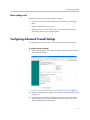
Configuring Advanced Firewall Settings . . . . . . . . . . . . . . . . . . . . . . . . . . . 6–3
Advanced setting rules . . . . . . . . . . . . . . . . . . . . . . . . . . . . . . . . . . . . . . 6–4
Enabling or disabling the firewall . . . . . . . . . . . . . . . . . . . . . . . . . . . . . 6–4
Administrative Options . . . . . . . . . . . . . . . . . . . . . . . . . . . 7–1
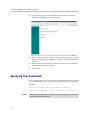
Changing the Administration Password . . . . . . . . . . . . . . . . . . . . . . . . . . . 7–1
Specifying User Commands . . . . . . . . . . . . . . . . . . . . . . . . . . . . . . . . . . . . . . 7–2
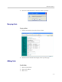
Managing SIP, MGCP or H.323 Clients . . . . . . . . . . . . . . . . . . . . . . . . . . . . 7–3
Selecting a client . . . . . . . . . . . . . . . . . . . . . . . . . . . . . . . . . . . . . . . . . . . . 7–4
Deleting clients . . . . . . . . . . . . . . . . . . . . . . . . . . . . . . . . . . . . . . . . . . . . . 7–4
Querying clients . . . . . . . . . . . . . . . . . . . . . . . . . . . . . . . . . . . . . . . . . . . . 7–5
Adding clients . . . . . . . . . . . . . . . . . . . . . . . . . . . . . . . . . . . . . . . . . . . . . . 7–5
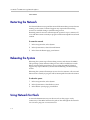
Restarting the Network . . . . . . . . . . . . . . . . . . . . . . . . . . . . . . . . . . . . . . . . . . 7–6
Rebooting the System . . . . . . . . . . . . . . . . . . . . . . . . . . . . . . . . . . . . . . . . . . . 7–6
Using Network Test Tools . . . . . . . . . . . . . . . . . . . . . . . . . . . . . . . . . . . . . . . 7–6
Running a ping test . . . . . . . . . . . . . . . . . . . . . . . . . . . . . . . . . . . . . . . . . 7–7
Running a traceroute test . . . . . . . . . . . . . . . . . . . . . . . . . . . . . . . . . . . . 7–7
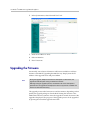
Upgrading the Firmware . . . . . . . . . . . . . . . . . . . . . . . . . . . . . . . . . . . . . . . . 7–8
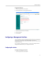
Configuring a Management Interface . . . . . . . . . . . . . . . . . . . . . . . . . . . . . . 7–9
Configuring the interface . . . . . . . . . . . . . . . . . . . . . . . . . . . . . . . . . . . . 7–9
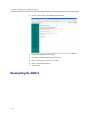
Reconnecting the 6400-S . . . . . . . . . . . . . . . . . . . . . . . . . . . . . . . . . . . . . . . . 7–10
Figure 1. Move the connection from Port 2 to Port 3 . . . . . . . . . 7–11
Configuring the Trusted Management Addresses . . . . . . . . . . . . . . . . . . 7–11
Setting the Provider MTU Size . . . . . . . . . . . . . . . . . . . . . . . . . . . . . . . . . . 7–12
Enabling SNMP . . . . . . . . . . . . . . . . . . . . . . . . . . . . . . . . . . . . . . . . . . . . . . . 7–13
Disabling SNMP . . . . . . . . . . . . . . . . . . . . . . . . . . . . . . . . . . . . . . . . . . . 7–15
Enabling remote system logging . . . . . . . . . . . . . . . . . . . . . . . . . . . . . 7–15
3
User Guide V2IU 6400-S Converged Network Appliance
Disabling remote system logging . . . . . . . . . . . . . . . . . . . . . . . . . . . . . 7–17
Setting the System Date and Time . . . . . . . . . . . . . . . . . . . . . . . . . . . . . . . 7–17
Creating a Static Route . . . . . . . . . . . . . . . . . . . . . . . . . . . . . . . . . . . . . . . . . 7–18
Appendix . . . . . . . . . . . . . . . . . . . . . . . . . . . . . . .Appendix–1
Troubleshooting Tips . . . . . . . . . . . . . . . . . . . . . . . . . . . . . . . . . . . Appendix–1
Trouble accessing the Internet . . . . . . . . . . . . . . . . . . . . . . . . Appendix–1
No dial tone . . . . . . . . . . . . . . . . . . . . . . . . . . . . . . . . . . . . . . . . Appendix–1
Checking the ALG registration code . . . . . . . . . . . . . . . . . . . Appendix–2
Telephone doesn't register with the softswitch . . . . . . . . . . Appendix–2
Checking the configurations on the ALG page . . . . . . . . . . Appendix–2
Pinging the softswitch . . . . . . . . . . . . . . . . . . . . . . . . . . . . . . . Appendix–2
Regulatory Notices . . . . . . . . . . . . . . . . . Regulatory Notices–1
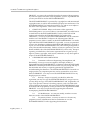
END-USER LICENSE AGREEMENT FOR POLYCOM® SOFTWARE .
Regulatory Notices–1
Compliance and Compatibility . . . . . . . . . . . . . . Regulatory Notices–12
4
1
Introduction
Introducing the V2IU 6400-S Converged Network Appliance
Installed at the edge of the operations center, 6400-S Series converged network
appliances secure critical voice, video and data infrastructure components
such as VoIP softswitches, video Gatekeepers, gateways and media servers.
This chapter contains the following sections:
•
Introducing the V2IU 6400-S Converged Network Appliance
•
Features
•
Physical Connections and Specifications
•
Management Features
1-1
User Guide V2IU 6400-S Converged Network Appliance
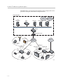
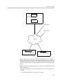
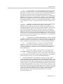
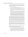
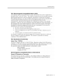
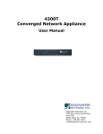
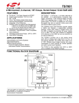
The 6400-S Series converged network appliances can be deployed in service
provider or enterprise environments as depicted below.
Service Provider
ISDN,
PSTN Network
PSTN
H.323
Gatekeeper
NMS
Softswitch
Gateway
MCU
6400-S
Aggregation Router
Hotspot
NAT/Firewall
Public IP
Network
PSTN
SIP Voice
User
T-1/E-1
Company A
NxT-1/E-1
Company B
Aggregation
Router
6400-S
4300T
H.323 Video
Endpoint
Gateway
V500
IP
Phone
Laptop
IP
Phone
H.323 Video
Endpoint
EM015
1-2
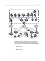
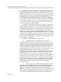
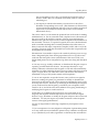
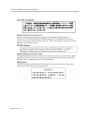
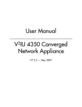
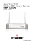
Introduction
Headquarters
PC
H.323
Gatekeeper
Application
Server
Softswitch
PC
NMS
PC
IP Phone
PSTN
Gateway
6400-S
6400-E
IP Phone
IP Phone
Aggregation Router
IP
Network
PSTN
T-1/E-1
Branch Office
PSTN
NxT-1/E-1
Aggregation
Router
Company B
6400-E
4300T
Gateway
H.323
H.323
Endpoint
Gateway
PC
Laptop
IP Phone
IP Phone
EM016
The 6400-S is designed to protect managed VoIP service providers and
enterprise customers from network-based attacks. It combines topology
hiding, dynamic session admission control and stateful packet inspection to
secure critical voice, video and data infrastructure components.This chapter
introduces the:
•
Functional features
•
Hardware features
•
Management features
1-3
User Guide V2IU 6400-S Converged Network Appliance
Features
•
Resolves firewall traversal problems at the Network Operations Center for
VoIP by providing a VoIP application layer gateway (ALG) or voice and
video aware firewall that supports SIP, MGCP and H.323
•
Resolves firewall traversal problems at customer offices for VoIP by
providing NAT-Traversal capability for SIP.
•
Supports up to 10,000 concurrent VoIP calls or up to 85 Mbps of H.323
video traffic
•
Protects the enterprise LAN using a stateful packet inspection (SPI)
firewall for both voice and data traffic
•
Performs static IP routing
•
Provides integrated test tools to facilitate problem isolation
•
Performs TFTP relay for IP phone images
•
Uses a simple web based GUI for configuration and management
•
Supports logging to external syslog servers and interfaces to network
management systems using SNMP
Physical Connections and Specifications
Port
Description
Subscriber (ETH0) Ethernet
This port is a 10/100 auto sensing port. It
is connected through an Ethernet switch
to IP phones, IADs or PCs installed on the
public network.
Port 1
Provider (ETH1) Ethernet
Port 2
Out of Band Management
Port 3
Console Port (COM 1)
1-4
This port is a 10/100 auto sensing port. It
is connected to the private network.
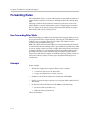
This port can be configured to allow out of
band management sessions. It is typically
connected to a private management
network.
This port is used to establish a local
console session with the EdgeProtect
using a VT100 terminal or emulation
program. The baud rate is 9600. It is used
for debug or local diagnostic purposes
only.
Introduction
Port
Description
Dimensions
Compact 2U design - 3.45"(H) x
17.11"(W) x 20"(D)
Weight
45 lbs (20411 grams)
Power
Dual, redundant 500W AC supplies
Dual, redundant 470W DC supplies
Warranty
1 Year
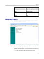
Management Features
The 6400-S is configured and managed through the Configuration Menu, a
web-based Graphical User Interface.
Access the Configuration Menu by entering a URL in a web browser such as
Internet Explorer, Netscape, or Firefox.
Using the Configuration Menu, you can set a wide range of network services,
including:
•
Provider and subscriber settings and related network settings.
1-5
User Guide V2IU 6400-S Converged Network Appliance
•
Remote system logging.
•
VoIP and subnet routing.
•
Firewall
•
Administration, maintenance and upgrading.
The following chapters give you detailed processing steps you need to set up
the 6400-S.
1-6
2
Installing the 6400-S
Physical Installation1
Anchor the equipment rack that will contain the 6400.
The equipment rack must be anchored to an unmovable support to prevent it
from falling over when one or more systems are extended in front of the rack
on slides. You must also consider the weight of any other device installed in
the rack. A crush hazard exists should the rack tilt forward which could cause
serious injury.
If AC power supplies are installed
Mains AC power disconnect
The AC power cord(s) is considered the mains disconnect for the 6400-S and
must be readily accessible when installed. If the individual server power
cord(s) will not be readily accessible for disconnection then you are
responsible for installing an AC power disconnect for the entire rack unit. This
main disconnect must be readily accessible, and it must be labeled as
controlling power to the entire rack, not just to the 6400-S. To remove all
power, two AC cords must be removed.
Grounding the rack installation
To avoid the potential for an electrical shock hazard, you must include a third
wire safety ground conductor with the rack installation. If the 6400-S power
cord is plugged into an AC outlet that is part of the rack, then you must
provide proper grounding for the rack itself. If the 6400-S power cord is
plugged into a wall AC outlet, the safety ground conductor in the power cord
provides proper grounding only for the 6400-S. You must provide additional,
proper grounding for the rack and other devices installed in it.
1
Intel® Telco/Industrial Grade Server TIGPR2U Product Guide
2-1
User Guide V2IU 6400-S Converged Network Appliance
Overcurrent protection
The 6400-S is designed for an AC line voltage source with up to 20 amperes of
overcurrent protection per cord feed. If the power system for the equipment
rack is installed on a branch circuit with more than 20 amperes of protection,
you must provide supplemental protection for the 6400-S. The overall current
rating of a 6400-S configured with two power supplies is less than 4 amperes.
If DC power supplies are installed:
Connection with a DC source should only be performed by trained service
personnel. The 6400-S with DC input is to be installed in a Restricted Access
Location in accordance with articles 110-16, 110-17, and 110-18 of the National
Electric Code, ANSI/NFPA 70. The DC source must be electrically isolated by
double or reinforced insulation from any hazardous AC source. The DC
source must be capable of providing up to 650 Watts of continuous power per
feed pair.
Main DC power disconnect:
You are responsible for installing a properly rated DC power disconnect for
the 6400-S system. This mains disconnect must be readily accessible, and it
must be labeled as controlling power to the 6400-S. The circuit breaker of a
centralized DC power system may be used as a disconnect device when easily
accessible and should be rated no more than 10 amps.
Grounding the 6400-S
To avoid the potential for an electrical shock hazard, you must reliably connect
an earth grounding conductor to the 6400-S. The earth grounding conductor
must be a minimum 14AWG connected to the earth ground stud(s) on the rear
of the 6400-S. The safety ground conductor should be connected to the chassis
stud with a Listed closed two-hole crimp terminal with a maximum width of
0.25 inch. The nuts on the chassis earth ground studs should be installed with
a 10 in/lbs torque. The safety ground conductor provides proper grounding
only for the 6400-S. You must provide additional, proper grounding for the
rack and other devices installed in it.
Overcurrent protection
Overcurrent protection circuit breakers must be provided as part of each host
equipment rack and must be incorporated in the field wiring between the DC
source and the 6400-S. The branch circuit protection shall be rated minimum
75Vdc, 10 A maximum per feed pair. If the DC power system for the
equipment rack is installed with more than 10 amperes of protection, you must
provide supplemental protection for the 6400-S. The overall current rating of
a 6400-S configured with two power supplies is 8 amperes.
Do not attempt to modify or use an AC power cordset that is not the exact type
required. You must use a power cordset that meets the following criteria:
2-2
Installing the 6400-S
•
Rating: For U.S./Canada cords must be UL Listed/CSA Certified type
SJT, 18-3 AWG. For outside U.S./Canada cords must be flexible
harmonized (<HAR>) or VDE certified cord with 3 x 0.75 mm conductors
rated 250 VAC.
•
Connector, wall outlet end: Cords must be terminated in grounding-type
male plug designed for use in your region. The connector must have
certification marks showing certification by an agency acceptable in your
region and for U.S. must be Listed and rated 125% of overall current
rating of the 6400-S.
•
Connector, 6400-S end: The connectors that plug into the AC receptacle
on the 6400-S must be an approved IEC 320, sheet C19, type female
connector.
•
Cord length and flexibility: Cords must be less than 4.5 meters (14.76 feet)
long. CAUTION Temperature: The temperature in which the 6400-S
operates when installed in an equipment rack, must not go below 5 °C (41
°F) or rise above 40 °C (104 °F). Extreme fluctuations in temperature can
cause a variety of problems in your 6400-S.
•
Ventilation: The equipment rack must provide sufficient airflow to the
front of the 6400-S to maintain proper cooling. The rack must also include
ventilation sufficient to exhaust a maximum of 1023 BTU's per hour for the
6400-S. The rack selected and the ventilation provided must be suitable to
the environment in which the 6400-S will be used.
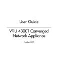
Power Supplies1
The power supply cage shown is accessed from the rear of the chassis. The
power supply cage supports up to two hot-swap power supplies (either AC
input or DC input) in a (1+1) redundant configuration. Only the DC input
version is NEBS certified. The combined output power to the 6400-S system is
470 Watts per DC supply and 500 Watts per AC supply.
DC Power Supply Interface Requirements
The DC power source may produce hazardous voltage levels exceeding -60
VDC and high energy levels above 240VA that may cause electric shock or
burns. All DC input connections should be made only by a qualified service
person to prevent injury. All wiring terminals connected to the DC input
terminal block must be fully insulated with no exposed bare metal.
The power supply will operate within all specified limits over the input
voltage range outlined as follows:
1
Intel® Telco/Industrial Grade Server TIGPR2U Product Guide
2-3
User Guide V2IU 6400-S Converged Network Appliance
Voltage
•
Minimum tolerance = -38VDC
•
Nominal rating = -48 to -60VDC
•
Maximum tolerance = -75VDS
•
Maximum input current = 17.0 Amps
The power supply will power-off if the DC input is less than -34 VDC.
DC Power Supply LED Indicators
Power Supply condition
Power Supply LED
No DC power to all PSUs
Off
No DC power to this PSU only
Amber
DC present/Only Standby Outputs On
Blink Green
Power supply DC outputs ON and OK
Green
Current limit
Amber
Power supply failure
Amber
AC Power Supply Interface Requirements
The AC power supply operates within the following limits:
•
AC line voltage = Auto-ranging for either 100-127 VAC or 200-240 VAC
•
AC line frequency = 50/60 Hz
•
AC input current = 4 Amp at 100-127 VAC, 2 Amp at 200-240 VAC
AC Power Supply LED Indicators
2-4
Power Supply condition
Power Supply LED
No AC power to all PSUs
Off
No AC power to this PSU only
Amber
DC present/Only Standby Outputs On
Blink Green
Power supply DC outputs ON and OK
Green
Power supply in Alert Condition
Blink Amber
Power supply failure
Amber
3
Configuring the V2IU 6400-S
Configure the 6400-S using a web browser such as Internet Explorer or
Netscape Navigator. The 6400-S is shipped with a pre-configured IP address
for its Subscriber (Port 1) interface.
This chapter gives you the information you need to get started. It contains the
following sections:
•
Connecting to the 6400-S
•
Logging In and Out of the 6400-S
•
Navigating Through the Configuration Pages
•
Read-only User
•
Getting Help
Connecting to the 6400-S
You need to connect to the 6400-S before you can configure it to work with
your network. Connect using the supplied preset IP address and subnet
mask. You are also supplied with a default user ID and password.
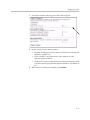
To connect to the 6400-S:
1. Connect a PC using an IP address of 192.168.1.2 and subnet mask of
255.255.255.0 to Port 1 of the 6400-S.
2. Launch a web browser on the PC and enter the URL string: 192.168.1.1.
3-1
User Guide V2IU 6400-S Converged Network Appliance
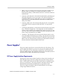
3. Press Return.
The Main Configuration Menu appears.
4. To log in, select Network from the navigation bar.
5. In the Connect to pop-up enter the following default information:
— For username: root
— For password: default
Caution
3-2
To maintain your network security, be sure to change the default username and
password as described under Changing the Administration Password on page 7-1.
Configuring the V2IU 6400-S
6. Continue to configure the system using the information provided in
subsequent chapters of this guide.
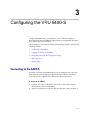
Logging In and Out of the 6400-S
You are prompted to log in every time you point a new browser session to the
Configuration URL.
To log out, simply close your browser.
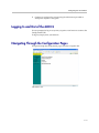
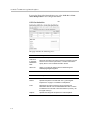
Navigating Through the Configuration Pages
Navigate through the configuration pages from the navigation bar.
The choices are:
3-3
User Guide V2IU 6400-S Converged Network Appliance
Menu
Description
Network
Through the Network page, you can
configure a wide range of multimedia
network services. These services can be
enabled or disabled depending on the
functionality required for a network
configuration. The device's network
settings include configuring the Subscriber
and Provider interfaces, DNS and Default
Gateway.
VoIP ALG
Using the VoIP ALG page, you can
configure the connectivity and
management for Subscriber and Provider
voice and video over IP devices.
Firewall
Through the Firewall page, you can
configure the 6400-S to act as a firewall
for voice, video and data traffic.
System
Through the System menu you have
access to a variety of configuration
operations and status information.
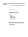
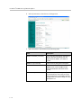
Read-only User
This feature works by creating a new user with read-only access to the
system. All information is displayed in a non-changeable form. Information
changed in entry boxes cannot be submitted. In fact, most Submit and OK
buttons are not visible.
Note: You must have administrator privileges and log in as an administrator
to change read-only user.
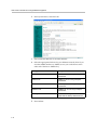
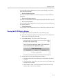
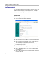
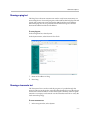
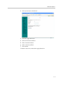
Enabling a Read-only User
To enable a read-only user, use the following steps:
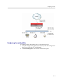
1. Using the configuration graphical user interface, from the Configuration
Menu on the left-hand side, click Network.
Note: You must have administrator access and log in as an administrator
to change read-only user.
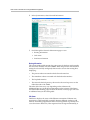
2. Scroll down to the area of the screen shown below.
3-4
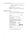
Configuring the V2IU 6400-S
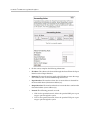
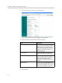
3. Click changed. The following window screen appears:
Note: All open web browsers must be closed when you change between
administrative user “root” and read-only “rouser.”
4. Enter a new password. The password must be a minimum of six
characters long.
4. Re-enter the new password to confirm it.
5. Click Submit.
Now when you access the system using this user name (rouser) and password,
all fields are read-only.
Getting Help
You can get help from several sources in the Configuration Menu.
•
By pressing Help in the navigation bar.
•
Following the link in Info at the top of the various Configuration pages.
•
From the links on the Configuration Menu home page.
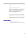
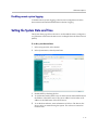
Getting information about the network
You can view a variety of information about the network from Network Information in the System menu. Networking Information displays the low-level
IP network and interface configuration of the 6400-S.
To view network information:
1. In the navigation bar, select System.
3-5
User Guide V2IU 6400-S Converged Network Appliance
2. In the System menu, select Network Information.
3. Scroll through the Network Information page to view:
— Routing information
— Link status
— Interface information
Routing Information
The system routing table contains the static routes for the hosts and networks
that are on the Provider side of the 6400-S. When the provider and subscriber
settings have been fully configured, there must be at least four routing lines
displaying:
•
The private subnet associated with the Provider interface.
•
The immediate subnet associated with the Subscriber interface.
•
The loopback interface.
•
The network's default gateway, this must be the next-hop-router on the
Subscriber side of the 6400-S.
The order of the lines may vary depending on the subnet masks.
Additional lines may be displayed depending on the contents of the Route
and VoIP Subnet Routing pages. Each of the entries on these pages will cause
an additional entry in the routing table.
Link Status
Link Status displays the status of the Ethernet connections. Ethernet auto
negotiation is often unreliable, especially between different vendors or old
and new networking equipment. Failure of auto negotiation is generally not a
cause for concern. However, if the negotiated rates change intermittently, or
3-6
Configuring the V2IU 6400-S
the link is down or there is no link, the link rate may need to be set manually
on the Set Link Rate page. Intermittent data and voice outages may be caused
by auto negotiation “flutter”. Setting the link rate manually is recommended
and ensures that the device at the far end of the connection will not renegotiate rates during VoIP operation.
Interface Information
The specific status and configuration information for the system interfaces is
displayed in the Interface Information section. The MAC address of interface
eth0 is needed to retrieve the VoIP ALG License Key if the license information
is lost.
The interface statistics can point to areas of congestion in the network. If the
errors statistic increase during normal operation of the device, it may be an
indication of excessive congestion on the network interface. If the congestion
is not corrected, the quality of voice calls will be affected. The topology of the
network attached to the network interface with the errors should be examined and modified to better segment and isolate network traffic. See Link Status on page 3-6.
Getting information about the system
You can view a variety of information about the network from System Information in the System menu. System Information displays detailed information regarding the operating system running on the 6400-S. Customer support
may ask you to examine or forward this information when troubleshooting
problems with the 6400-S.
To view system information:
1. In the navigation bar, select System.
3-7
User Guide V2IU 6400-S Converged Network Appliance
2. In the System menu, select System Information.
3. Scroll through the System Information page to view:
— System uptime
— Number of active streams
— Recent call log
— Process information
— Memory usage
— System logging messages
System uptime
System Uptime displays the current time, the amount of time elapsed since
the last system reboot, and the system load averages for the past one, five,
and 15 minutes. Uptime can help identify when a power outage may have
interrupted service. Load averages greater than two indicate excessive system
loading and could indicate over provisioning of the VoIP ALG feature.
Number of active streams
The number of active streams indicates how many calls are transiting the
6400-S (crossing from Subscriber to Provider interfaces) OR being hair-pinned
by the 6400-S as part of its NAT-Traversal facility. Calls that are in progress
and between two devices on one side of the 6400-S are not counted in this
number.
3-8
Configuring the V2IU 6400-S
Recent Call Log
The Recent Call Log displays quality information about calls that are in
progress or have recently completed. If a call falls below the configured MOS
Threshold, a system log message is created. The MOS score for a call is always
displayed when the call is completed. Detailed statistics for the call are
reported in the Advanced MOS syslog message.
Process Information
Process Information displays detailed process table information that may be
of use to technical support.
Memory Usage
Memory Usage displays detailed memory allocation information that may be
of use to technical support.
System Logging Messages
System Logging Messages displays information logged during system boot
and normal operation. Logging messages may indicate unauthorized
attempts to access the 6400-S, process restart messages, and excess resource
utilization messages.
3-9
User Guide V2IU 6400-S Converged Network Appliance
3 - 10
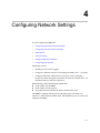
4
Configuring Network Settings
You can configure the 6400-S for:
•
Configuring Subscriber Interface Settings
•
Configuring Provider Interface Settings
•
Subinterfaces
•
ToS Byte Setting
•
Setting the Ethernet Link Rate
•
Configuring the Network
Optionally, you can:
•
Enabling remote system logging.
•
Configure a different interface for managing the 6400-S. See 7, for details.
•
Configure additional administrative operations, such as changing
the password and setting the system date and time are available. See 7, for
details about these, and other operations.
Before Starting, collect the following information:
An IP address for the 6400-S.
An IP address for the gateway.
The preferred and secondary IP address for the DNS server.
The 6400-S is shipped with the preset subscriber (Port 1) IP address of:
192.168.1.1, and the default subnet mask: 255.255.255.0 so you can access and
configure the 6400-S.
4-1
User Guide V2IU 6400-S Converged Network Appliance
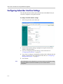
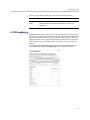
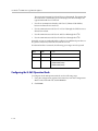
Configuring Subscriber Interface Settings
The subscriber interface defines the interface between the 6400-S and your
customers’ endpoints or the public network.
To configure subscriber interface settings:
1. In the navigation bar, select Network.
\
2. In Subscriber Interface Settings, highlight and replace the default IP
Address and Subnet Mask.
3. If you are configuring network settings, see the instructions in
“Configuring the Network” on page 4-9.
4. If you want to configure a management interface that is different than the
default, complete all of the configuration tasks, then see “Configuring a
Management Interface” on page 7-9.
5. Press Submit.
Note
4-2
After submitting the new configurations, you need to reconnect to the 6400-S using
the new IP address and subnet mask before you can continue with the
configuration.
Configuring Network Settings
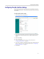
Configuring Provider Interface Settings
The provider interface defines the interface between the 6400-S and internal
voice, video and data devices. This interface is generally connected to the private network.
To configure provider interface settings:
1. In the navigation bar, select Network
2. In Provider Interface Settings, select Static IP Address (the most common
configuration), or DHCP if a DHCP server assigns the 6400-S internal
address.
3. Enter an IP Address.
4. Enter a Subnet Mask.
5. If you are configuring network settings, see the instructions in
“Configuring the Network” on page 4-9.
6. If you want to configure a management interface that is different than the
default, complete all of the configuration tasks, then see “Configuring a
Management Interface” on page 7-9.
7. Press Submit.
4-3
User Guide V2IU 6400-S Converged Network Appliance
Subinterfaces
The Subinterfaces feature allows a system administrator to assign additional
IP addresses to interfaces. These are sometimes referred to as aliases or
loopback interfaces. An additional address may be assigned to the system’s
WAN interface to support, for example, another management IP address.
How Subinterfaces Works
A common use for subinterfaces is forwarding a public subnet. A subinterface
may be created to support a subnet forwarded through the Polycom V2IU
6400-S. When forwarding a subnet through the Polycom V2IU 6400-S, it is
necessary to assign an address for this subnet to the system to act as the
subnet's gateway. To configure forwarding rules, use the Forwarding Rules
submenu under the Firewall configuration link.
When applied to the WAN/Provider interface, these addresses are protected
by the same firewall policy that is applied to the WAN/Provider address.
Several other features in the system automatically create Subinterfaces. VRRP
(if supported) and Static NAT automatically create Subinterfaces.
When viewing the Network Information page, Subinterfaces are designated in
the Interface Information section with the device name and number, separated
by a colon (for example, eth0:100).
Configuring Subinterfaces
To configure subinterfaces, use the following steps:
1. Using the configuration graphical user interface, from the Configuration
Menu on the left-hand side, click Network.
4-4
Configuring Network Settings
2. Click Subinterfaces. The window shown below opens.
3. On this screen, complete the following information:
•
IP Address is the address to be assigned to the subinterface.
•
Netmask is the network mask to use for the address. If several addresses
are applied to an interface and these addresses are in a common network,
they must use a common subnet. The system does not support
supernetting.
•
Interface is the port where the subinterfaces will be configured.
4. When you have finished entering this information, click Add. The
following popup appears:
5. Click OK. The new subinterfaces entry appears on the Subinterfaces
window in the list area.
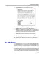
ToS Byte Setting
Since the Internet itself has no direct knowledge of how to optimize the path
for a particular application or user, the IP protocol provides a limited facility
for upper layer protocols to convey hints to the Internet Layer about how the
trade-offs should be made for the particular packet. This facility is the “Type
of Service” or ToS facility.
ToS settings allow the service provider to prioritize time sensitive traffic, such
as voice plus video to ensure minimized packet loss and delay through their
network. When providing end-to-end QOS, it is important that the voice plus
4-5
User Guide V2IU 6400-S Converged Network Appliance
video traffic be placed in the correct queues to deliver a higher QOS than
regular traffic. Regular traffic, that is not time sensitive, can be delayed with
little or no indication to the user, while the slightest delay in voice plus video
can cause auditable differences. The ToS byte setting helps prioritize traffic
going to the WAN so a provider can prioritize the traffic correctly in its
network.
Although the ToS facility has been a part of the IP specification since the
beginning, it has been little used in the past. However, the Internet host
specification now mandates that hosts use the ToS facility. Additionally,
routing protocols (including OSPF and Integrated IS-IS) have been developed
which can compute routes separately for each type of service. These new
routing protocols make it practical for routers to consider the requested type
of service when making routing decisions.
How the ToS Byte Setting Works
For all RTP traffic (voice and video), the Polycom V2IU 6400-S marks the ToS
byte in the IP header as “High Priority,” and strips (set to 0) the ToS byte for
all other traffic. Unchecking the “Enable ToS Byte Stripping” option means
that the ToS byte will not be stripped from non-RTP traffic, but will remain
unchanged.
Note: For most situations, you should leave this setting as it is. Only change it
if your provider indicates that you should do so.
Viewing or Changing the ToS Byte Setting
To view or change the ToS byte setting, use the following steps:
1. Using the configuration graphical user interface, from the Configuration
Menu on the left-hand side, click Traffic Shaper.
2. Scroll down the area of the screen shown below.
4-6
Configuring Network Settings
3. For most situations, you should leave this setting as it is. Only change it if
your provider indicates that you should do so. If your provider indicates
that you need to change the ToS byte setting, that provider should also
provide the other parameters required on this screen.
4. If you have changed the values, click Submit to activate the new settings.
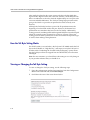
Setting the Ethernet Link Rate
Ethernet autonegotiation is often unreliable, especially between different vendors or old and new networking equipment. Failure of autonegotiation is
generally not a cause for concern. However, if the negotiated rates change
intermittently or the link is reported as no link or down, the link rate may
need to be set manually. An interface that “flutters” because of the autonegotiation setting, may cause intermittent voice and data outages.
Note
The vast majority of Ethernet networking devices including the 6400-S use
“autonegotiate” as a default setting. Chances are that you will not have to set the
Ethernet link rate. Please use caution if manually configuring the link rate, as a
speed or duplex mismatch will result in a loss of connectivity.
If needed, configure the rate of the physical Ethernet port on the 6400-S. The
default setting for the Ethernet port is autonegotiate, and it applies to both the
link speed and duplex with locally attached devices.
The link rate of an interface can be assigned to a desired rate. A network
administrator may want to set the rate manually if autonegotiation fails to
select a rate consistently or if it selects a rate that is slower than the maximum
rate supported by both interfaces.
To set the link rate:
1. In the navigation bar, select System.
4-7
User Guide V2IU 6400-S Converged Network Appliance
2. In the System menu, select Set Link.
3. Select Subscriber Ethernet or Provider Ethernet.
4. Select the appropriate link rate for your Ethernet network (Note: If you
set either 6400-S interfaces to 100FD, be sure you set the device at the
other end of the line to 100FD also.):
Setting
Description
10baseT-HD
10Mbits per second using half duplex
transmission
10baseT-FD
10Mbits per second using full duplex
transmission
100baseT-HD
100Mbits per second using half duplex
transmission
100baseT-FD
100Mbits per second using full duplex
transmission
Autonegotiate
The 6400-S autonegotiates link rate and
duplex with the directly attached device.
5. Press Submit.
4-8
Configuring Network Settings
Configuring the Network
Use network settings to configure the default gateway address, and the primary and secondary DNS servers.
Packets destined for IP addresses not known to the 6400-S are forwarded to
the Default Gateway for handling. For the 6400-S the Default Gateway MUST
be the next hop router attached to Port 1 (the Subscriber interface).
The primary DNS server is used by the 6400-S to resolve domain names to IP
addresses. The secondary DNS server is used in the event the primary DNS
server is unreachable.
To configure network settings:
1. In the Network page, move to the Network Settings section.
2. Enter an IP address for the Default Gateway
This must be the next-hop-router connected to Port 1, the Subscriber side
interface
3. Enter the Primary DNS Server.
4. Enter the Secondary DNS Server.
5. Press Submit.
4-9
User Guide V2IU 6400-S Converged Network Appliance
4 - 10
4
Configuring for Video
This chapter describes how to configure the Polycom V2IU 6400-S to support
video:
•
H.323 Configuration
•
Forwarding Rules
•
Peering Proxy
•
Clients List Lock
•
H.323 Activity Monitor
•
H.460 Operation Mode
4-1
User Guide V2IU 6400-S Converged Network Appliance
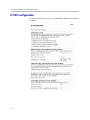
H.323 Configuration
To access the H.323 Settings page, select VoIP ALG > H.323 in the Configuration Menu.
4-2
Configuring for Video
The H.323 Settings page has the following areas:
•
Gatekeeper Mode
•
WAN/Provider-side gatekeeper mode settings
•
LAN/Subscriber-side gatekeeper mode settings
•
Embedded gatekeeper mode settings
•
LRQ Size
•
Default Alias
•
Stale Time
•
Multicast Messages
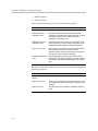
4-3
User Guide V2IU 6400-S Converged Network Appliance
•
H.460.18 Support
•
Alias Restrictions
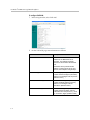
In the Gatekeeper mode area, select one of the following modes:
Item
Description
None
H.323 is disabled.
WAN/Provider-side
gatekeeper mode
Specifies that the system will forward all client RAS
messages to the gatekeeper. If this is selected, you must
configure the settings in the WAN/Provider-side
gatekeeper mode settings area.
LAN/Subscriber-side
gatekeeper mode
Specifies that the system will act as a gatekeeper. If this
option is selected, you must configure the settings in the
LAN/Subscriber-side gatekeeper mode settings area.
Peering-Proxy mode
Allows calls to be forwarded to other endpoints based on
the information sent from the endpoints. All the
information about routing the call must be sent as part of
the request or prefixes must be configured.
Embedded gatekeeper
mode
Provides gatekeeper functions and accepts endpoint
registrations. If this option is selected, you must configure
the settings in the Embedded gatekeeper mode settings
area.
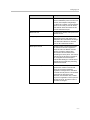
If WAN/Provider-Side Gatekeeper mode is selected, you must configure the
following parameters:
4-4
Item
Description
WAN/Provider-side GK
address
Specifies the IP address of the gatekeeper
Modify Time-To-Live
Allows you to override the value for time-to-live returned
by the gatekeeper before forwarding the response to the
endpoint.
New Time-To-Live
Specifies how long an endpoint's registration should be
valid.
Configuring for Video
If LAN/Subscriber-Side Gatekeeper mode is selected, you must configure the
following parameters:
Item
Description
LAN/Subscriber-side GK
address
Enter the IP address of the gatekeeper.
Allow public IP in LCF
Select the checkbox if the gatekeeper has been deployed
with multiple outbound proxies and must decide which
proxy to use based on the IP address returned in the LCF.
This is an advanced configuration option and should
usually not be selected.
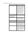
If Embedded Gatekeeper is selected, you must configure the following
parameters:
Item
Description
Time-to-Live(s)
Enter a time in seconds. This setting controls how
long an endpoint’s registration should be valid. At
the end of this period the endpoint sends another
registration request.
Prevent calls from
unregistered endpoints:
Blocks unregistered LAN-side endpoints from
making calls through the device.
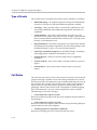
In the LRQ Size area, you can limit the number of source aliases in a
forwarded LRQ message to a maximum of two to allow interoperability with
gatekeepers that cannot handle more than two source aliases.
In the Default Alias area, you can specify a default alias to be added to incoming calls without a destination message in the Q.931 Setup message. This alias
allows the embedded gatekeeper or a LAN/Subscriber-side gatekeeper to
route the call to a default endpoint. Enter a default alias and select one of the
following types:
•
E.164
•
H.323
In the Stale Time area, you can arrange to delete clients that have not sent any
registration requests for the specified interval. This area includes the
following configurable parameters:
Item
Description
Delete stale clients
Select this checkbox to enable the stale timer feature.
Stale time (m)
Specify the length of the interval in minutes.
4-5
User Guide V2IU 6400-S Converged Network Appliance
Some RAS messages can be multicast in order to automatically detect gatekeepers. In the Multicast Messages area, you can enable listening to multicast
messages. This area includes the following configurable parameter:
Item
Description
Listen to multicast
messages
Select this checkbox to enable listening to multicast
messages.
In the H.460.18 Support area, you can configure H.460.18 support. This allows
the system to do NAT/Firewall traversal for clients behind NAT or firewall
devices. This area includes the following configurable parameters:
Item
Description
Disabled
Disables H.460.18 support.
Enabled
Enables H.460.18 support.
Keep-alive time(s)
Specifies the keep-alive time if H.460.18 support is
enabled.
In the Alias Restrictions area, you can set a limit on the number of aliases that
are allowed to register with the system. If this number is exceeded when a client tries to register, the registration is rejected. This area includes the following parameter:
Item
Description
Max Aliases
Enter the maximum number of allowed aliases. If the value is set
to 0, the maximum is not enforced.
The H.323 Settings page includes the following two buttons:
4-6
Item
Description
Submit
Applies the settings configured on this page.
Reset
Clears all fields and selections and allows you to enter new
information.
Configuring for Video
H.323 Activity
To access the H.323 Activity page, select VoIP ALG > H.323 Activity in the
Configuration Menu.
The H.323 Activity page is a read-only page that shows the following information:
•
Current time
•
WAN Gatekeeper status
•
Current payload bandwidth
•
Estimated total bandwidth
•
Activity log of recent H.323 events
H.323 Alias Manipulation
Alias manipulation is performed immediately when a message (such as an
ARQ, LRQ or a Setup) is received. Any matching pattern is replaced with the
specified string, allowing you to replace characters or strings that are hard or
impossible to dial on certain endpoints. Normal call look-up is performed
following alias manipulation.
4-7
User Guide V2IU 6400-S Converged Network Appliance
To access the H.323 Alias Manipulation page, select VoIP ALG > H.323
>Alias Manipulation in the Configuration Menu.
This page includes the following areas:
4-8
Item
Description
Destination
H323-ID or
E.164 Alias
Modification
table
Lists alias manipulation rules.
Add a rule
Allows you to add new prefixes to the Prefix Routing and
Gatekeeping Neighboring table.
Item
Description
Action
Indicates whether the rule is to be added or edited.
Pattern
Specifies the pattern to be matched. See <l_link>“Regular
Expressions” on page 11 for details on valid patterns.
Index
Determines the order in which the rule is scanned in the
Destination H323-ID or E.164 Alias Modification table. To add a
rule between two rules with consecutive indexes (n and m), use
the higher index (m).
Replace
Specifies the string that will replace the matched pattern.
Rules are executed in the order in which they are listed. Use the
arrows to move entries up and down, or use the Index field to
specify where a new or edited rule falls in the list.
Configuring for Video
The H.323 Alias Manipulation page includes the following buttons:
Item
Description
Commit
Applies the settings configured on this page.
Reset
Clears all fields and selections and allows you to enter new
information.
H.323 Neighboring
Neighboring and prefix routing can be used to route calls based on a matching prefix in the destination alias of the call. The call decision is made following alias manipulation and acts on the modified string, similar to other call
lookup processes such as registered client look-up. Each prefix is associated
with a domain name or IP address that is used in the event that the prefix
matches.
To access the H.323 Neighboring page (formerly the Prefix Routing page),
select VoIP ALG > H.323 > Neighboring in the Configuration Menu.
4-9
User Guide V2IU 6400-S Converged Network Appliance
This page includes the following areas:
Item
Description
Prefix Routing
and
Gatekeeper
Neighboring
table
Lists rules for forwarding incoming calls based on their dialed
alias.
Add a prefix
Allows you to add new prefixes to the Prefix Routing and
Gatekeeper Neighboring table.
Item
Description
Action
Indicates whether the rule is to be added or edited.
Prefix
Specifies the prefix pattern to be matched against the dialing
string. See <l_link>“Regular Expressions” on page 11 for details
on valid patterns.
Index
Determines the order in which the rule is scanned in the Prefix and
Gatekeeper Neighboring table. To add a rule between two rules
with consecutive indexes (n and m), use the higher index (m).
Strip
Indicates whether the matching prefix is stripped from the dialing
string.
Add
Specifies a string to be prepended to the dialing string.
Neighbor
Determines whether a location request (LRQ) is sent when this
prefix matches.
Rules are executed in the order in which they are listed. Use the
arrows to move entries up and down, or use the Index field to
specify where a new or edited rule falls in the list.
•
If enabled, the prefix becomes a neighboring statement.
•
If disabled, the incoming Q.931 Setup is forwarded to the given
address without a preceding LRQ.
This field is used for interoperability with other gatekeepers that
may not accept a Setup without a preceding LRQ.
Local Zone
Provides compatibility with remote gatekeepers that are
configured to accept LRQs only from sources that match its
configured remote zone. If a gatekeeper is configured to accept
requests only from a known source, enter the zone in this field.
Address
Specifies the IP address or domain name of the device to which
the call is to be forwarded.
The H.323 Neighboring page includes the following buttons:
4 - 10
Item
Description
Commit
Applies the settings configured on this page.
Reset
Clears all fields and selections and allows you to enter new
information.
Configuring for Video
Regular Expressions
Alias manipulation patterns and prefixes use regular expressions to match a
string in the destination alias. A regular expression can be a string of literal
characters to match or a set of special expressions.
Alias manipulation patterns can match a sub-string at any location and
number of times within the alias. Prefixes are always searched from the left of
the alias and cannot match a middle part or the end of the alias.
Regular expressions are listed in <l_link>Table 1 and <l_link>Table 2 lists
some example expressions.
Table 1 Regular Expressions
Symbol
Description
.
Matches any single character.
[]
Matches any single character listed between the []. For example,
[abc], [123]. If the characters are separated by a -, all characters
between the two are matching, e.g. [a-z], [0-9]
()
Matches the literal string given, e.g. (abc)
|
Matches the block on either side of the |, e.g. a|b.
?
Matches 0 or 1 of the preceding block.
*
Matches 0 or more of the preceding block.
+
Matches 1 or more of the preceding block.
\
Escapes the special meaning of the next character.
{a}
Matches exactly 'a' numbers of the preceding block.
{a,}
Matches 'a' or more of the preceding block.
{a,b}
Matches between 'a' and 'b' (inclusive) of the preceding block.
Table 2 Example Regular Expressions
Expression
Description
100
Matches the string 100.
(555)?123
Matches 555123 or 123.
(408|555)
Matches 408 or 555.
555[0-9]{3}
Matches 555 followed by exactly 3 digits.
#
Matches the character '#'.
\*
Matches the character '*'. Note that '*' by itself is a regular
expression and must therefore be escaped with a '\' to match the
character itself.
4 - 11
User Guide V2IU 6400-S Converged Network Appliance
Forwarding Rules
Forwarding Rules allows a system administrator to forward data traffic for a
subnet from one interface to another, overriding the Firewall’s default drop
rules.
Allowing a subnet to be forwarded is commonly used when servers with
public addresses are placed behind the system. Configuring the network in
this way allows the system to manage and prioritize bandwidth, sharing it
between the VoIP services and the servers.
How Forwarding Rules Works
When forwarding, one address from the forwarded range of addresses must
be assigned to the rule's output interface. The Polycom V2IU 6400-S uses this
address to act as a gateway router for the subnet. The address may be
assigned using the Subinterfaces page.
Note: The subnet and forwarded addresses are not protected by the firewall.
A similar method for forwarding traffic is provided by Proxy ARP. Proxy ARP
is used to “bridge” addresses within a single subnet range from one interface
to another. Often this is used to bridge and forward a public address to the
protected side of the system without having to subnet the public address
range. Proxy ARP does not require an additional gateway address on the system for the subnet, but does not allow port and protocol filtering for forwarded data.
Example
In this example:
•
The ISP has supplied two separate subnets to the customer:
— A small one (2 hosts) for the WAN link
— A large one (254 hosts) for a bank of servers
•
67.40.41.2 is the WAN IP address for the Polycom V2IU 6400-S
•
NAT is a private IP range of 192.168.1.xxx using the WAN address for PCs
and Phones
•
On the LAN side of the Polycom V2IU 6400-S are the following:
— Private IP subnet (192.168.1.xxx)
— Public IP subnet (67.40.40.xxx)
This is shown below.
4 - 12
Configuring for Video
Configuring Forwarding Rules
To configure address forwarding rules, use the following steps:
1.
Using the configuration graphical user interface, from the Configuration
Menu on the left-hand side, click Firewall.
2.
Click Forwarding Rules. The window shown below opens.
4 - 13
User Guide V2IU 6400-S Converged Network Appliance
3.
On this screen, complete the following information:
•
IP Subnet: The subnet to be forward through the firewall from the Input
Interface to the Output Interface.
•
Netmask: The network mask to apply to the IP Subnet to create the range
of IP addresses that are forwarded through the firewall.
•
Input Interface: The interface where data is received that is destined for
the forwarded subnet (destination address(es)).
•
Output Interface: The interface where data is received that is sent from the
forwarded subnet (source address(es)).
•
Protocol: The following protocols are used:
— UDP: for the specified network, allows the specified UDP port or port
range to pass through the system
— TCP: for the specified network, allows the specified TCP port or port
range to pass through the system
4 - 14
Configuring for Video
— Any: for the specified network, allows all ports and protocols through
the system. No ports are required because not all protocols support
the concept of ports.
•
Port or Port Range: The port number or port range allowed through the
system when UDP or TCP are selected. A port range is specified by
separating the starting and ending ports with a colon ':' (for example,
22:80). The ports parameter is not supported when you select Any
protocol because not all protocols support the concept of ports.
4.
When you have finished entering this information, click Add.
5.
Click OK. The new forwarding entry appears on the Forwarding Rules
window in the list area.
Peering Proxy
H.323 prefixes can be used to route calls based on a matching prefix in the
destination alias of the call. Each prefix is associated with a domain name or IP
address to send the call to in case the prefix matches.
The prefixes are searched in order, that is, the first prefix is tried first, and then
the next one on the list until the system finds a matching prefix. This means
that if there are multiple matching prefixes, the first one is used.
How Peering Proxy Works
The Polycom V2IU 6400-S supports the concept of an H.323 Peering Proxy.
This function provides advanced security layers or peering points within the
network where a security layer is needed. Peering Proxy allows network
providers to add internetworking connections between their “trusted”
network and an unknown network. This topology hides their trusted network
and the Stateful packet inspection Firewall provides the policies to ensure
security. You can add Peering Proxies in series with one another to push the
core H.323 networking infrastructure to meet individual security
requirements.
The illustration below shows a sample diagram with dial plan and call flow
examples. It is a snapshot of how the Peering Proxy can be deployed. Peering
Proxy however, is not limited to this specific scenario, so contact your Polycom
representative to discuss specific network requirements for full Peering Proxy
support.
4 - 15
User Guide V2IU 6400-S Converged Network Appliance
Note: A minimum configuration for Peering Proxy would be for inbound only
prefixes, since there may be many endpoints to statically route calls to. There
might also be a master gatekeeper to which all endpoints are registered. In this
case, you would only need 1 prefix pointing to the master gatekeeper and let
that gatekeeper signal the other endpoints directly.
In the example above, the Polycom V2IU 6400-S Peering Proxy is installed in
“Private Video Network A and B,” a peering point into this network. This
network could have additional peering points to allow topology spreading of
network resources. However, this example shows only a single point. Peering
4 - 16
Configuring for Video
Proxy provides an access point into this network and is responsible for the
E.164 dial plan using NANP (North American Numbering Plans or NPAs).
The NPAs in this case are 831 and 408.
Dial plan integrity is required to insure proper routing of prefix's. This means
that if users are to dial into your network, they could be required to enter a
“Prefix” on their V2IU with a corresponding destination IP. If the user was to
dial another user NOT destined to your network with the same beginning
prefix, the prefix configured on this V2IU would create a prefix match and the
call would route incorrectly. The call routes to the destination defined in the
prefix and not to the intended endpoint. The example shows “Private Video
Network A's Peering Proxy” with an inbound prefix defined as 8315…… Any
inbound call that matches 8315 with any 6 digits creates a prefix match and
sends the call to 10.10.11.1. Refer to “Regular Expressions” in the Info button
on the GUI interface for information on all the methods for defining prefixes.
Private Video Network A is one example of a V2IU configured in “LAN Side
Gatekeeper” mode with an ANNEX O dial method to dial “Off Net.” Internal
“On Net” endpoints registered to the LAN Side Gatekeeper will dial E.164
only. This allows any location to place calls to any location with an ANNEX O
dial plan, that is, E.164@WAN_IP or other V2IU's deployed on the network. In
this example a Peering Proxy has been deployed to allow dialing ingress and
egress to the Public Internet. At each V2IU location required to egress, the
Public Internet requires a “Prefix” to be configured. This allows that location's
endpoint to dial “Off Net” to the Public Internet. This prefix can be configured
to any digit and may be part of the externally dialed E.164 in the
E.164@WAN_IP, that is, to reach site A by dialing [email protected]
where the prefix is defined as 415* or 415……. In this example, a “9” was
chosen. The prefix is then mapped to the LAN interface of the Peering Proxy
10.10.11.1. The dial string is now [email protected] and a strip rule for
the prefix is applied. This is needed to route the call at the destination
correctly. If the Site C V2IU does not strip the “9”, the destination V2IU fails the
call with a “No Registered Client” message (call failures can be viewed under
the “H323 Activity” page in the GUI), since the “9” becomes part of the E.164.
If you choose a prefix that matches the destination E.164, set Site C's V2IU to
NOT strip matching prefixes.
NOTE: In this illustration E.164@WAN_IP was used as an example. Peering
Proxy and all V2IU's support user@host ANNEX O dialing methods, for
example [email protected] or [email protected] or [email protected] with a DNS SRV record
configured to point to an A record for the WAN IP of the V2IU.
The following sections demonstrate the Dial Plan for ingress and egress calls
to Private Video Network A as shown in the illustration.
Outbound from Site C to Site A
Site C dials an endpoint located at Site A: [email protected]. The
PathNavigator receives the call and generates a Q.931setup to the V2IU for that
subnet. The V2IU processes the Q.931 setup from the calling endpoint. The
V2IU looks for a prefix match. In this case, the “9” creates a match. The “Strip
Matching Prefix” rule is applied, the “9” is stripped, and the call is routed to
4 - 17
User Guide V2IU 6400-S Converged Network Appliance
the Peering Proxy IP 10.10.10.1. The Peering Proxy applies the same rule set, in
this case, NO matching prefix is found and ANNEX O dialing is applied. The
call is now routed to Site A's V2IU. The call is forwarded to the LAN Side
PathNavigator where the registered client with the E.164 of 4155551000 is
located and the call is gatekeeper routed to the called endpoint.
Inbound from Site A to Site C
Site A dials: [email protected]. (The destination IP is the Peering Proxy
WAN IP address.) The Peering Proxy is configured with prefix 8315……and is
mapped to the WAN IP of the V2IU 10.10.11.1. As explained earlier, the prefix
could be 831* or 83, and so on, depending upon dial plan requirements. The
PathNavigator receives the Q.931setup from the endpoint and forwards the
call to the V2IU for that subnet. The V2IU receives the Q.931 setup from the
calling endpoint. The V2IU looks for a prefix match, finds NO matching prefix,
and ANNEX O dialing is applied. The call is now routed to the Peering Proxy
IP 67.40.40.4. The Peering Proxy receives the Q.931 setup and looks for a prefix
match, in this case “8315” creates a match. The Peering Proxy now changes the
destination IP to 10.10.11.1 and routes the call to Site C's V2IU. The Q.931 setup
is forwarded to the LAN Side PathNavigator where the registered client with
the E.164 of 8315551000 is located, and the call is gatekeeper routed to the
called endpoint.
Outbound from Site C to Site D
Site C dials an endpoint located at Site D: [email protected]. The
PathNavigator receives the call and generates a Q.931 setup to the V2IU for
that subnet. The V2IU processes the Q.931 setup from the calling endpoint. The
V2IU looks for a prefix match, in this case the “9” creates a match. The “Strip
Matching Prefix” rule is applied, the “9” is striped, and the call is routed to the
Peering Proxy IP 10.10.10.1. The Peering Proxy applies the same rule set, in this
case NO matching prefix is found, and ANNEX O dialing is applied. The call
is now routed to the Peering Proxy for “Private Video Network B” IP
68.30.30.4. The Peering Proxy receives the Q.931 and looks for a prefix match.
In this case, “5125” creates a match. The Peering Proxy now changes the
destination IP to 172.16.2.1 and routes the call to Site D's V2IU. The V2IU is
configured for Embedded Gatekeeper Mode. In this mode, the endpoint is
directly registered and an E.164 registered client match is made. The call is
then routed to the called endpoint.
Outbound from Site D to Site B
Site D dials an endpoint located at Site B: [email protected]. The V2IU
Embedded Gatekeeper is configured with a prefix of “9” to point to Peering
Proxy 172.16.1.1. The V2IU looks for a prefix match. In this case, the “9” creates
a match. The “Strip Matching Prefix” rule is applied, the “9” is striped, and the
call is routed to Peering Proxy IP 172.16.1.1. The Peering Proxy applies the
same rule set. In this case NO matching prefix is found and ANNEX O dialing
is applied. The call is now routed to Site B. The V2IU is configured for
4 - 18
Configuring for Video
Embedded Gatekeeper Mode. In this mode, the endpoint is directly registered,
an E.164 registered client match is made, and the call is routed to the called
endpoint.
Outbound from Site C to Public IP Endpoint
Site C dials the public endpoint: [email protected]. The PathNavigator receives the
call and generates a Q.931 setup to the V2IU for that subnet. The V2IU receives
the Call setup from the calling endpoint, and the V2IU looks for a prefix match.
In this case, the “9” creates a match. The “Strip Matching Prefix” rule is
applied, the “9” is striped, and the call is routed to the Peering Proxy IP
10.10.10.1. The Peering Proxy applies the same rule set, in this case NO
matching prefix is found, and direct IP dialing is applied.
Inbound from Public IP Endpoint to Site C
Public IP endpoint is NOT registered to a gatekeeper and must dial an IP+EXT
to reach Site C's endpoint,. In this case, the IP address is 67.40.40.4 and EXT
8315551000. The Peering Proxy receives the call and looks for a prefix match.
In this case “8315” creates a match. The Peering Proxy now changes the
destination IP to 10.10.11.1 and routes the call to Site C's V2IU. The Q.931 setup
is forwarded to the LAN Side PathNavigator where the registered client with
the E.164 of 8315551000 is located, and the call is gatekeeper routed to the
called endpoint.
Configuring Peering Proxy
To configure peering proxy, use the following steps:
1. Using the configuration graphical user interface, from the Configuration
Menu on the left-hand side, click VoIP ALG.
2. Click H.323. The window shown below opens.
4 - 19
User Guide V2IU 6400-S Converged Network Appliance
3. On this screen, check “Peering-Proxy mode”.
4. Scroll to the bottom of the window and click Submit.
Adding an H.323 Prefix Entry
You can add prefixes by entering the prefix string and the target address.
To add an H.323 prefix entry, use the following steps:
1. Using the configuration graphical user interface, from the Configuration
Menu on the right-hand side, click VoIP ALG.
2. Click H.323 Prefixes. The window shown below opens.
4 - 20
Configuring for Video
The prefix routing table shows all currently configured prefixes. The
prefixes are searched in the order they are entered. Each prefix can be
moved up or down in the list. You can select and delete prefixes.
3. To strip a matching prefix, select the checkbox and click Submit.
If you enable this, all matching prefixes are stripped from the destination
alias before the call is forwarded.
4. To add an entry, enter the prefix and the address.
The prefix string can be a regular expression as described above. The
target address can be a domain name or an IP address.
5. Click Add. The new entry appears in the table.
Clients List Lock
Client List lockdown allows you to prevent new clients from registering. This
is done as follows:
•
Creating a client, as follows:
4 - 21
User Guide V2IU 6400-S Converged Network Appliance
— Manually entering all clients that are allowed to use the system
— Running the system without the Client List lockdown feature until all
desired clients have registered
• Enabling this feature.
This feature is useful for lists involved with 911 usage.
When this feature is in effect, any message from an unauthorized SIP client
will be rejected with a “403 Forbidden” response. MGCP messages will be
discarded.
Enabling the Clients List Lock
To configure clients list lock, use the following steps:
6. Using the configuration graphical user interface, from the Configuration
Menu on the left-hand side, click VoIP ALG. The following window
appears.
3. On this screen, check “Enable Client List lockdown”.
4. Scroll to the bottom of the window and click Submit.
4 - 22
Configuring for Video
H.323 Activity Monitor
The H.323 Activity Monitor shows any recent H.323 events that may be of
interest to the administrator of the system. The information appears in three
columns:
•
Event/Time
•
Source
• Destination
Following this information are a number of lines with event specific information such as call-id, duration, call-status, and so on.
Abnormal events have their event specific information listed in red.
4 - 23
User Guide V2IU 6400-S Converged Network Appliance
Type of Events
The events that may currently be listed in the activity monitor are as follows:
•
Bandwidth change - the endpoint requested a change of the bandwidth
used for its call, only sent if the bandwidth management is enabled.
•
Call Setup – Only sent if the call was ‘successfully’ established. A call is
successfully established if the H.245 media negotiation connection was
established.
•
Call Termination – Sent when a call terminates. You can have a call
termination event without a call setup event, for example, a failed call that
doesn’t reach the H.245 established state will not cause a call setup event,
but only a call termination event.
•
Registration Reject – Sent when a registration was rejected. This includes
the authority that rejected the registration (our side or the gatekeeper (only
in WAN GK mode) as well as a text reason for the rejection.
•
Gatekeeper reachability changed (only in WAN GK mode). Gatekeeper
status toggled from reachable to unreachable or vice versa.
•
Location Request – Received a location request from a neighboring
gatekeeper.
•
Location Confirm – Sent, or forwarded, a location confirm to a previous
request.
•
Location Reject - Sent, or forwarded, a location reject to a previous
request.
Call Status
The call status shows the last state of the call at the time of the event. Each call
progresses through a number of states when being established. If a call fails,
the call-status in the call termination event can help trouble-shoot the cause of
the call failure. For example, if the call fails at the “Caller/Callee admission
request received” state, there may be a problem communicating with the
gatekeeper, whereas if the call fails at the “Attempting to establish outgoing
Q.931 TCP connection” state, the remote endpoint may not be reachable.
The following are call status messages:
• “Caller admission request received”
Received an admission request from the source endpoint and forwarded it to
the gatekeeper.
• “Caller admission response received”
Received an admission response (either confirm or reject) from the gatekeeper
and forwarded it to the source endpoint.
• “Incoming Q.931 TCP connection established”
Received an incoming Q.931 TCP connection from the source.
4 - 24
Configuring for Video
• “Attempting to establish outgoing Q.931 TCP connection”
Successfully resolved the destination of the call and attempting to establish an
outgoing Q.931 TCP connection to the destination.
• “Q.931 signaling received and forwarded”
Both Q.931 TCP connections have been successfully established and Q.931
signaling has been received and forwarded.
• “Callee admission request received”
Received an admission request from the destination endpoint and forwarded
it to the gatekeeper.
• “Callee admission response received”
Received an admission response (either confirm or reject) from the gatekeeper
and forwarded it to the destination endpoint.
• “Incoming H.245 TCP connection established”
Received an incoming H.245 TCP connection from the source.
• “Attempting to establish outgoing H.245 TCP connection”
Attempting to establish an outgoing H.245 TCP connection to the destination.
• “H.245 signaling received and forwarded”
Both H.245 TCP connections have been successfully established and H.245
signaling has been received and forwarded. At this point, the call is considered established, even though no media channels have been opened up yet.
• “Outgoing media channel established”
An outgoing media channel (from the LAN/subscriber side to the WAN/provider side) has been opened.
• “Incoming media channel established”
An incoming media channel (from the WAN/provider side to the LAN/subscriber side) has been opened.
• “Bidirectional media channels established”
Media channels have been opened in both directions. This is a normal call
where media is being sent in both directions.
4 - 25
User Guide V2IU 6400-S Converged Network Appliance
Call Termination
The call termination cause may also give some information about why the call
terminated or failed to be established.
• “Out of system resources”
The call could not be completed because the system was out of system
resources.
• “Client owning the call has been deleted”
The call could not be completed because the client that made this call was
deleted during the call setup.
• “Connection to destination could not be established”
A TCP connection to the destination could not be established.
• “Connection refused by destination”
The call could not be completed because the destination refused the incoming
TCP connection.
• “No route to destination”
A TCP connection to the destination could not be established because the destination could not be reached. This could happen if there is no route to the
destination or, if the destination is on the same subnet, the destination does
not answer to ARP requests.
• “Connection to destination timed out”
The TCP connection attempt to the destination timed out before it could be
established.
• “Call ended by source”
The call was gracefully terminated by H.323 signaling from the source. This
usually indicates that the endpoint intended to terminate the call.
• “Call ended by destination”
The call was gracefully terminated by H.323 signaling from the destination.
This usually indicates that the endpoint intended to terminate the call.
• “Connection terminated by source”
The call was terminated because the source terminated the TCP connection
without prior call termination signaling.
• “Connection terminated by destination”
The call was terminated because the destination terminated the TCP connection without prior call termination signaling.
• “No admission confirm received”
The call could not be established because the admission response was not
received from the gatekeeper.
• “Cannot resolve destination”
The call could not be established because the destination could not be
resolved.
•
4 - 26
“At maximum bandwidth usage”
Configuring for Video
The call could not be established because the system already is at the maximum allowed bandwidth.
• “Received admission reject”
The call was terminated because an admission reject was received from the
gatekeeper.
• “Received disengage request”
The call was terminated because the endpoint requested to tear down the call.
• “Received invalid data”
The call could not be established because the system received invalid data on
the signaling channel.
• “Cannot find client”
The call could not be established because the called client could not be found.
Viewing the H.323 Activity Monitor
To configure the H.323 Activity Monitor, use the following steps:
5. Using the configuration graphical user interface, from the Configuration
Menu on the left-hand side, click VoIP.
6. Click H.323 Activity. The window shown below opens.
2. On this screen, the event list contains three columns:
— The Event/Time field - shows the type of event and the time that it
occurred.
— The Source field - shows the source of the event as an IP address and
an alias (when available).
— The Destination field - shows the destination of the event as an IP
address and an alias (when available).
4 - 27
User Guide V2IU 6400-S Converged Network Appliance
H.460 Operation Mode
This feature allows the Polycom V2IU 6400-S to do NAT/Firewall traversal for
clients behind NAT or firewall devices.
The endpoint must always signal H.460.18 capability for this feature to be
enabled.
Note: For this to be fully functional, it must be enabled with H.460 capability
on both ends.
How H.460 Operation Mode Works
H.460.18 is an extension to H.323 for traversing NAT/Firewalls when
communicating between H.323 devices. Typically a NAT/Firewall will block
any incoming connection attempts from a public-side host to a private-side
host.
The figure below shows a basic configuration of video users with both firewall
and non-firewall connections.
4 - 28
Configuring for Video
Gatekeeper
Video User D
V2IU-S
Video User E
Video User C
Internet
NAT/Firewall
Video User A
Video User F
NAT/Firewall
Trusted
Video User B
H.323 requires many connections in order to establish a call, for example,
Q.931 and H.245 TCP connections and multiple RTP UDP streams. H.460.18
allows an H.323 device to traverse a NAT/Firewall by having the private-side
endpoint initiate all TCP connections and UDP streams to the outside H.323
device.
Note: When NAT/Firewall connections are configured, H.323 Fixup software
must be turned off.
In the previous figure, the following communication between video users is
available:
•
User D communicates to Users A, B, C, E, and F.
4 - 29
User Guide V2IU 6400-S Converged Network Appliance
The connection between User D and User A is hairpinned. This means that
the connection is 768 kilobits per second (kbps) or 2 times 384 kbps, the
typical bandwidth for a H.323 call.
•
User E can communicate directly with User C (Shortest Path Media)
because no firewalls are involved.
•
User A communicates with User C or User E through the V2IU because a
firewall is involved.
•
User D communicates with User A and User B through the V2IU.
•
User A communicates with User F and User A through the V2IU.
Normally, as long as outbound traffic is allowed, no additional ports have to
be opened on the NAT/Firewall for H.460.18 to work.
If outbound traffic is restricted, the following port ranges must be opened.
RAS
UDP
1719
Q.931
TCP
1720
H.245
TCP
14085:15084
RTP
UDP
16386:17286 (4200/4300)
16386:25386 (5300)
16386:34386 (6400)
Configuring the H.460 Operation Mode
To configure the H.460 Operation Mode, use the following steps:
1. Using the configuration graphical user interface, from the Configuration
Menu on the left-hand side, click VoIP ALG.
2. Click H.323.
4 - 30
Configuring for Video
3. Scroll down until the following part of the window appears.
4. On this screen, use the following options:
— Disabled – disabled (The system will not use H.460.18 even though the
endpoint is capable of it.)
— Always enabled – The system always turns H.460.18 on if the
endpoint signals capability.
— The keep-alive time is the interval between keep-alive messages (used
to keep the firewall open) that the endpoint should use. The default is
30s.
5. When you have entered your selections, click Submit.
4 - 31
User Guide V2IU 6400-S Converged Network Appliance
4 - 32
5
Configuring VoIP
An application-layer gateway provides basic proxy features for voice and
video over IP traffic. Serving as an ALG proxy, the 6400-S provides Network
Address Translation (NAT) services for the protected softswitch, gatekeeper
or other media devices. It maps multiple devices on the subscriber interface
(public) to a single IP address on the provider interface (private). The ALG
must first recognize and register a public network based device before it
presents traffic from the IP telephone, video endpoint or data device through
its provider port.
The 6400-S contains an MGCP, SIP, and H.323 call-control proxy ALG. VoIP
phones, video endponts and client adapters have to be configured to point to
the 6400-S as the call-control server, proxy, gatekeeper or gateway (depending
on protocol). The 6400-S then forward this traffic onto the actual call-control
server or gatekeeper.
For corporate customers with high-end routers and firewalls, the 6400-S can be
configured as a VoIP Application Layer Gateway only. This allows all of the
normal data traffic to continue to be handled by the existing network devices,
and only voice or traffic to be handled by the 6400-S. For this configuration, the
6400-S Subscriber Ethernet port is connected to the internet. The 6400-S
Provider Ethernet port is connected to a port on the local Ethernet switch.
5-1
User Guide V2IU 6400-S Converged Network Appliance
To configure VoIP ALG:
1. In the navigation bar, select VoIP ALG.
2. On the VoIP ALG page, enter information as follows:
Field
Description
MGCP Server IP Address
If a MGCP ALG is needed, enter the IP
address for the MGCP Server as
provided. This address should be
reached via the Provider side Ethernet
port.
The MGCP server provides media
gateway control protocol service to IP
phones, client adapters and gateways.
5-2
MGCP Call Agent Port
The Call Agent port specifies the port
number that the Call Agent (soft-switch)
listens to for messages from the phones.
(Default is 2727)
MGCP Media Gateway Port
The Media Gateway port specifies the port
number the Media Gateway (phones)
listens to for messages from the
soft-switch. (Default is 2427)
MGCP Notified Entity Port
The Notified Entity port specifies the port
number that the soft-switch uses for
notifications from the phones, e.g. hook
up, hook down, digits. (Default is 2432)
Configuring VoIP
Field
Description
SIP Server Address
The SIP server provides
session-initialization protocol service to IP
phones, client adapters and gateways.
If a SIP ALG is needed, enter the address
(either an IP or URL) for the SIP Server.
This address should be reached via the
Provider side Ethernet port.
SIP Server Port
If a SIP ALG is needed, enter a port for the
SIP Server Port.
Always hairpin SIP media
Normally set to False. If set to True, then
SIP phone-to-phone calls made on the
Subscriber side of the 6400-S will always
have their RTP traffic flow to and back
from the EP's subscriber interface.
SIP Expires override
The SIP Expires override field specifies
the number of seconds a registration
should be valid. The 6400-S uses this
value to re-write the expires value
returned from the soft-switch before
forwarding it to the IP phone. This value is
used to force the IP phone to register at
the configured interval And helps to
maintain NAT bindings in network based
firewalls when the 6400-S is performing
NAT/firewall traversal.
SIP Soft-Switch Expires override
The SIP Soft-Switch expires override field
specifies the number of seconds that
should be used when forwarding
registration messages to the soft-switch
on behalf of the IP phones. This should be
higher than the rate pacing value,
otherwise, the soft-switch may consider
the phone's registration to have expired. If
this field is not set, the phone's value is
forwarded unchanged.
5-3
User Guide V2IU 6400-S Converged Network Appliance
Field
Description
SIP Register pacing
If the SIP Expires override field is set to a
lower value, the number of registration
messages may overload the soft-switch.
In order to prevent this, you can set the
SIP Register pacing field to the number of
seconds to wait before forwarding a
register message from one phone to the
soft-switch. Any register messages
received before this time will be locally
answered by the 6400-S. For example,
you may set the expires value to 60 and
the pacing value to 1800 to have the
phone register to the 6400-S every
minute, but only let a register message
through to the soft-switch every 30
minutes.
TFTP Server IP Address
Enter the IP address for the TFTP Server.
This allows the 6400-S to forward
(proxy) TFTP requests from devices
on the Subscriber side to a TFTP
server on the Provider side.
5-4
H232 Gatekeeper IP Address
If an H.323 ALG is needed, enter the
address (either an IP or URL) for the
H.323 Gatekeeper. This address should
be reached via the Provider side Ethernet
port.
Use ALG Alias IP Addresses
Not used
ALG Subscriber Interface
Not Used.
Automatic MCCP Re-registration
Automatic MGCP Re-registration is used
to re-register MGCP endpoints every time
the network or system restarts. Enable
this feature to automatically synchronize
the softswitch and phones immediately
after a restart. The default is Enabled.
MGCP Re-registration Rate(s)
The MGCP Re-registration Rate is used to
set the number of MGCP RSIP messages
to send per second to the Media Gateway
Controller when re-registration is needed.
If the MGCP Re-registration Rate needs to
be changed, enter a value between 1 and
5. Generally, this value does not need to
be modified. The default value is 5
msg/second.
Configuring VoIP
Field
Description
Automatic MGCP Audit
The Automatic MGCP Audit flag specifies
whether MGCP clients should be
automatically audited by sending a
message to each client and wait for a
response.
Audit Cycle Interval
The Audit Cycle Interval specifies how
often these messages should be sent out
to the clients. For each cycle, all endpoints
are audited so the rate of messages being
sent is dependent on the number of clients
currently registered.
State Time
The Stale Time value is used to decide
when a client is supposed to be deemed
stale, or unavailable.
Prevent state re-registration
The Prevent stale re-registration flag can
be used to disable the automatic MGCP
re-registration feature for stale clients.
Automatic Client Deletion
Automatic Client Deletion will delete
clients that have been unavailable for a
given period of time.
Deletion Time
Deletion Time specifies the time that a
stale client will show a warning icon in the
client list.
H 323 Terminal Type
The H.323 TerminalType is used to
specify the type of terminal that the
6400-S should use. This value should be
set to endpoint.
Maximum bandwidth (kbps)
This value is not used and should be set
to 0.
Current payload bandwidth
The total bandwidth in use for H.323 video
calls as requested by the H.323 video
endpoints.
Estimated total bandwidth
The total bandwidth in use for video calls;
generally the current payload bandwidth
plus 20% for packet overhead.
H 323 Max Aliases
This value is not used and should be set
to 0.
5-5
User Guide V2IU 6400-S Converged Network Appliance
Field
Description
SIP LAN side Gateway
The SIP LAN Side Gateway is used to
configure a LAN side SIP gateway to
which calls that are not for a registered
phone can be sent. The name of the
gateway is a locally meaningful name.
These two fields must both be filled in, or
be empty.
Gateway Name
The name of a subscriber PSTN gateway
or a single SIP proxy for multiple PSTN
gateways.
Gateway Address
The IP address of a subscriber PSTN
gateway or a single SIP proxy for multiple
PSTN gateways.
Configuring VoIP subnet routing
In its simplest configuration, the 6400-S acts as a proxy for a soft-switch or
H.323 gatekeeper on its immediate Provider subnet. Because these devices
reside on the same subnet as the 6400-S, packets proxied by the ALG function
do not require additional routing information.
The 6400-S can support a VoIP call-control server or H.323 gatekeeper on it's
Provider side but not located immediately on the Provider-side subnet by
configuring VoIP Subnet Routes.
Using the VoIP Subnet Routing feature, the 6400-S can be configured to serve
these remote devices. Three pieces of information are required for each subnet
containing the VoIP call-control server or H.323 gatekeeper:
•
The IP Network address.
•
The Netmask.
•
The Gateway.
You can configure up to 20 VoIP subnets.
To configure VoIP subnet routing:
1. In the navigation bar, select System.
5-6
Configuring VoIP
2. In the System menu, select VoIP Subnet Routing.
3. Enter the network address in IP Network, such as 10.10.12.0.
This is the IP address of the remote subnet containing the voice devices.
4. Enter a subnet mask in Netmask, such as 255.255.255.0
A subnet mask of the network determines which packets are destined for
the 6400-S.
5. Enter and address in Gateway, such as 10.10.10.2.
This is the IP address of the intermediate router that knows the return path
to the remote subnet from the 6400-S.
6. Press Submit.
7. You can configure as many as 20 subnets. Complete steps 3 through 6 for
each subnet.
Deleting a VoIP subnet route
To delete a VoIP subnet route:
1. In the navigation bar, select System.
2. In the System menu, select VoIP Subnet Route.
3. Enter an IP Network, such as 10.10.10. 0.
4. Check the Delete Subnet box.
5. Press Submit.
5-7
User Guide V2IU 6400-S Converged Network Appliance
Configuring VRRP
The Virtual Router Redundancy Protocol (VRRP) is designed to eliminate the
6400-S as a single point of failure in a network configuration. Two 6400-S
devices can be configured to perform as a redundant pair. One 6400-S is the
Master, the other is the Backup. If the Master fails because of a network or
hardware failure, the Backup takes over for the Master.
To configure VRRP:
1. In the navigation bar, select System.
2. In the System menu, select VRRP Configuration.
3. To enable VRRP, check the Enable VRRP box.
4. Enter a Subscriber IF Virtual IP Address. The common virtual IP address
to be shared on the Port 1 interface.
5. Enter a Subscriber IF Virtual Routing ID. A unique number in the range
1-255 that identifies the router for the Subscriber virtual IP.
6. Enter a Provider IF Virtual IP Address. The common virtual IP address to
be shared on the Port 2 interface.
7. Enter a Provider IF Virtual Routing ID. A unique number in the range
1-255 that identifies the router for the Provider virtual IP.
8. Enter the VRRP Advertise Interval. How often (in seconds) that VRRP
packets should be sent.
9. Enter the VRRP Authentication Password. Password used to authenticate
routers in a VRRP group.
5-8
Configuring VoIP
10. Enter the Gratuitous ARP Delay. How long in seconds an 6400-S should
wait after a switch over before sending Gratuitous ARPs packets.
11. Press Submit.
5-9
User Guide V2IU 6400-S Converged Network Appliance
5 - 10
6
Configuring the Firewall
This chapter describes how to configure the 6400-S as a firewall. It contains the
following sections:
•
Configuring the Firewall Basic Settings
•
Configuring Advanced Firewall Settings
The 6400-S can act as a firewall. A firewall restricts and controls the traffic
between networks, typically between a corporate network and the Internet. If
an external firewall is used, the firewall features can be set to pass or block
traffic depending on whether the 6400-S is placed in series or in parallel with
the external firewall.
Configuring the Firewall Basic Settings
The basic settings are under Basic LAN (Subscriber) and WAN (Provider)
Firewall Settings on the Firewall configuration page.
6-1
User Guide V2IU 6400-S Converged Network Appliance
To configure basic settings:
1. In the navigation pane, select Firewall.
2. In the section: Basic LAN and WAN Firewall Settings, enable the
management services that you want to reach the 6400-S by checking the
appropriate box for:
— Allow HTTP access through firewall
— Allow TELNET access through firewall
— Allow SSH access through firewall
— Allow SNMP access through firewall
3. Configure Allow TCP Port according to the rules in “Basic settings rules”
on page 31. This setting allows traffic with the specified TCP port to
terminate on the 6400-S.
4. Configure Allow UDP Port according to the rules in Basic settings rules
on page 6-3. This setting allows traffic with the specified UDP port to
terminate on the 6400-S.
5. Skip Enable PPTP server Pass-through. This setting is not currently used.
6. Enter an IP address in PPTP Server IP Address. This setting is not
currently used.
7. To restrict Trusted Management to the Management Interface, see
Configuring a Management Interface on page 7-9.
8. Press Submit.
6-2
Configuring the Firewall
Basic settings rules
Follow these rules when configuring basic settings:
•
For Allow TCP Port and Allow UDP Port, valid values are 1 through
65535.
•
Separate multiple entries by spaces,
•
Indicate a range of values with a colon (:). For example, 25:50 means
perform the action on ports 25 through 50
Configuring Advanced Firewall Settings
A comprehensive security policy can be created using advanced settings.
To configure advanced settings:
1. In the navigation pane, select Firewall and scroll to Advanced LAN and
WAN Firewall Settings.
2. Enable to disable firewall logging. (See Enabling or disabling the firewall
on page 6-4.)
3. Configure Deny Hosts (IP) according to the rules in Advanced setting
rules on page 6-4. Deny Hosts (IP) denies all traffic with the source IP
address matching the specified hosts
6-3
User Guide V2IU 6400-S Converged Network Appliance
4. Configure Deny Hostwise TCP (IP-Port) according to the rules in
Advanced setting rules on page 6-4. This setting denies all traffic
matching the specified TCP port numbers and the specified source IP
addresses
5. Configure Deny Hostwise UDP (IP-Port) according to the rules in
Advanced setting rules on page 6-4. This feature denies all traffic
matching the specified UDP port numbers and the specified source IP
addresses
6. Configure Allow Hostwise TCP (IP-Port) according to the rules in
Advanced setting rules on page 6-4. This setting allows all traffic
matching the specified TCP port numbers and the specified source IP
addresses
7. Configure Allow Hostwise UDP (IP-Port) according to the rules in
Advanced setting rules on page 6-4. This setting allows all traffic
matching the specified UDP port numbers and the specified source IP
addresses
8. Press Submit.
Advanced setting rules
Follow these rules when configuring advanced settings:
•
Separate multiple entries with spaces.
•
Specify a port using the dash (-), as in 192.168.3.1-23 for Telnet.
•
Indicate a range of ports with a colon (:). For example, 192.168.3.1-23:50
means perform the action on ports 25 through 50
•
Classful IP addresses are assumed by default. For example: 192.168.3.1
uses a class “c” mask. Specify subnets using the forward slash (/), as in
192.168.3.1/24
Enabling or disabling the firewall
6-4
1.
To disable the firewall, check or uncheck the Enable Firewall box.
2.
Press Submit.
7
Administrative Options
The 6400-S supports a number of additional administrative operations. Using
these options you can:
•
Changing the Administration Password
•
Specifying User Commands
•
Managing SIP, MGCP or H.323 Clients
•
Restarting the Network
•
Rebooting the System
•
Using Network Test Tools
•
Upgrading the Firmware
•
Configuring a Management Interface
•
Reconnecting the 6400-S
•
Configuring the Trusted Management Addresses
•
Setting the Provider MTU Size
•
Enabling SNMP
•
Setting the System Date and Time
•
Creating a Static Route
Changing the Administration Password
We strongly recommend that you change the default password for the root
administrative account.
To change the password:
1. In the navigation bar, select System.
7-1
User Guide V2IU 6400-S Converged Network Appliance
2. On the System page, locate Change Password, and follow this link:
The password of the device can be changed.
3. Enter the New Password. The new password must be between 6 and 20
characters in length. Any combination of alpha and numeric characters is
accepted.
4. Enter the password again in the Confirm Password to ensure that there
were no mistakes in the initial entry.
5. Press Submit.
Specifying User Commands
User commands allow you to execute special operations that may be required
for your installation, such as creating user specific firewall or routing rules.
Examples:
ifconfig eth0:20 192.168.20.10 netmask 255.255.255.0
iptables -I POSTROUTING -t nat -s 192.168.20.10 -j ACCEPT
Caution
7-2
Use caution when adding user commands. The system may become unreachable if
an incorrect command is entered.
Administrative Options
To enter a user command:
1. Choose User Commands from the System menu on the navigation bar.
2. Enter a command in the User Commands: area.
3. Press Submit.
4. Restart the network to guarantee that the user commands are running.
See Restarting the Network on page 7-6.
Managing SIP, MGCP or H.323 Clients
You can view and manage information about devices that have registered as
clients with the 6400-S. This information is displayed on the Clients List page.
You can filter, sort, query, add and delete records.
Caution
Currently, MGCP clients can be added and deleted without restarting the 6400-S
but changes to SIP or H.323 clients list will automatically restart the 6400-S.
Use caution! All calls that are in progress will be interrupted.
7-3
User Guide V2IU 6400-S Converged Network Appliance
To work with the client list:
1. Choose Clients List from the System menu on the navigation bar.
2. Select a protocol from Protocol to display. The SIP client list is the default.
3. Perform an operation according to the instructions in:
— Filtering the clients list
— Deleting clients
— Querying clients
— Adding clients
Selecting a client
You can select a single client by entering a client identifier in the Client List
Filter field.
Deleting clients
1. To delete a client, click the trashcan in the No Sort column.
7-4
Administrative Options
2. Press OK to delete the client or Cancel to end the operation.
Querying clients
To query a client:
1. Click the Information Icon in the No Sort column.
2. Details about the selected client display at the top of the page.
Adding clients
To add a client:
1. Enter the client Name.
2. Enter an IP Address.
3. Enter a Port.
7-5
User Guide V2IU 6400-S Converged Network Appliance
Press Submit.
Restarting the Network
Use Network Restart to stop and the restart all the networking services that are
running on the system. Technical support may request that networking
services be restarted during a troubleshooting session.
Restarting network services will interrupt the system for up to a minute. All
voice and data sessions currently in progress will be interrupted! Proceed with
caution!
To restart the network:
1. In the navigation bar, select System.
2. In the System menu, select Network Restart.
3. In the Network Restart page, press Restart.
Rebooting the System
Rebooting the system stops all networking services and reboots the 6400-S.
The operating system and networking services will be loaded from scratch.
Reboot is functionally equivalent to power cycling the 6400-S. Technical
support may request that the system be rebooted during a troubleshooting
session.
Rebooting the system will interrupt services for a few minutes. All voice and
data sessions currently in progress will be interrupted! Proceed with caution!
To reboot the system:
1. In the navigation bar, select System.
2. In the System menu, select Reboot system.
3. In the Reboot system page, press Reboot.
Using Network Test Tools
A network administrator may use the test tools on this page to verify
connectivity of the 6400-S and trace the path of data throughout the network.
You can run a ping test or a traceroute test.
7-6
Administrative Options
Running a ping test
The Ping Test is the most common test used to verify basic connectivity to a
networking device. Successful ping test results indicate that both physical and
logical path connections exist between the 6400-S and the test IP address.
Successful ping tests do not guarantee that all data message are allowed
between the 6400-S and the test IP address.
To run a ping test:
In the navigation bar, select System.
In the System menu, select Network Test Tools.
1. Enter an IP Address to Ping.
2. Press Ping.
Running a traceroute test
The Traceroute Test is used to track the progress of a packet through the
network. The test can be used to verify that data destined for a provider device
reaches the remote IP address via the desired path. Similarly, network paths
internal to a company can be traced over the subscriber network to verify the
local network topology.
To run a traceroute test:
1. In the navigation bar, select System.
7-7
User Guide V2IU 6400-S Converged Network Appliance
2. In the System menu, select Network Test Tools.
3. Enter an IP Address to Trace
4. Select an Interface.
5. Press Traceroute.
Upgrading the Firmware
Occasionally, new releases of firmware will become available to add new
features to the 6400-S. Upgrading the 6400-S is easy. Simply enter the IP
address of the upgrade server and press Submit.
Note
During the upgrade, telephone services are interrupted. For this reason, the
upgrade should take place during a maintenance window.
Warning! During the upgrade process, the 6400-S must not be interrupted or
powered off. If the upgrade is interrupted, the device may become unusable and
need to be returned to the factory.
The upgrade process takes between two and five minutes, depending on how
quickly the upgrade package is downloaded. Writing the software to the
6400-S takes about five minutes. Once the upgrade is started, the status of the
upgrade is displayed. The progress of the upgrade process can be upgraded
by pressing the refresh the upgrade status link.
7-8
Administrative Options
To upgrade the firmware:
1. In the navigation bar, select System.
2. In the System menu, select Upgrade Firmware.
3. Enter an Download Server IP address.
4. Enter a Filename.
5. Press Submit.
Configuring a Management Interface
You can configure a specific management interface and restrict management
of the system to this interface only. When enabled, connections to
management protocols such as HTTP, SSH, SNMP, Telnet will only be allowed
through this interface.
If you configure a management interface, you must also configure trusted
management addresses when you configure the firewall.
Configuring the interface
To configure the Management Interface:
1. In the navigation bar, select System.
7-9
User Guide V2IU 6400-S Converged Network Appliance
2. On the System menu, select Management Interface.
3. On the Management Interface page:
4. Check the Enable Management Interface box.
5. Enter a Management Interface IP Address.
6. Enter a Subnet Mask address.
7. Press Submit.
Reconnecting the 6400-S
7 - 10
Administrative Options
1. Reconnect the 6400-S to the network by moving the connection from the
Provider port (Port 2) to the Optional Out of Band Ethernet Port (Port 3).
Figure 1. Move the connection from Port 2 to Port 3
2. Restart the system.
Configuring the Trusted Management Addresses
Trusted management addresses, define a list of trusted management host
addresses or network/masks. All other addresses are blocked from accessing
the device.
7 - 11
User Guide V2IU 6400-S Converged Network Appliance
To configure trusted management addresses:
1. In the navigation pane, select Firewall.
2. Within the Trusted Management Addresses, enter a list of trusted
management host addresses or network/masks. The basic firewall rules
will be applied only to those addresses. All other addresses will be
blocked from accessing the device.
If you do not include your management station, or a station to which you
have access, you lose access to the 6400-S. You can only reinstate access by
connecting to the serial console interface.
3. Press Submit.
Setting the Provider MTU Size
The Provider MTU size may be set to reduce the latency that is introduced
when large data packets are sent over a slow link. The default setting is 1500
bytes for static IP addresses. PPPoE links negotiate the value automatically
although the value can be overridden using this field. If the Upstream
Bandwidth is less than 256 Kbit/s, the MTU size is automatically reduced to
576 bytes.
When the link rate is set manually, ensure that the device at the far end of the
connection can communicate at the desired rate. Incompatible rates can cause
a loss of communication with the 6400-S!
7 - 12
Administrative Options
Caution
When manually configuring the MTU size we recommend that you use a setting of
800 bytes or greater. You may experience problems with certain types of VoIP
traffic if the MTU size is set below 800 bytes.
To set the Provider MTU size:
1. In the navigation bar, select System.
2. In the System menu, select Set Link.
3. Enter the Provider MTU size.
4. Press Submit.
Enabling SNMP
The 6400-S can be managed remotely by an SNMP network management
system such as HP Openview. The 6400-S supports SNMPv1 and MIB-II
(RFC1213). All MIB-II variables are read only. The MIB variables sysContact
and sysLocation are set by the web GUI.
To enable SNMP:
1. In the Navigation bar, select System.
7 - 13
User Guide V2IU 6400-S Converged Network Appliance
2. In the System menu, select Services Configuration.
3. Enter information as described in the following table.
7 - 14
Field
Description
SNMPv1 Read-Only Community
The community string that the management
station uses when accessing read-only
objects from the 6400-S. The default is
'public'.
SNMPv1 Trap Community
Trap community string place in trap pdus.
SNMPv3 User Name
If SNMPv3 is enabled, this field defines the
SNMPv3 user name for SNMPv3 USM
based authentication and VACm access
control.
SNMPv3 Passphrase
The SNMPv3 passphrase is optionally used
to authenticate the user as well as encrypt
the payload based on the SNMPv3 Security
setting below. The minimum length of a valid
passphrase is 8.
Administrative Options
Field
Description
SNMPv3 Security
The SNMPv3 security level for user
authentication and encryption of both
synchronous requests as well as
asynchronous traps. “None” means neither
SNMPv3 authentication or encryption are
used. “Auth(MD5)” means authenticating
user using MD5 hash algorithm.
“AuthPriv(MD5/DES)” means authentication
as well as encryption using the DES
encryption algorithm. The default value is
None.
SNMPv3 Trap Context
The SNMPv3 trap context defaults to nothing
but can be set to any string.
System Location
A comment string that can be used to
indicate the location of the 6400-S. By
default, no value is set.
System Contact
The administrative contact information for the
6400-S. By default, no value is set.
SNMP Port
The port that the 6400-S monitors to read
and send SNMP data. The default is 161.
4. Press Submit.
Disabling SNMP
To disable SNMP, select Services Configuration from the System menu and
uncheck the SNMP checkboxes.
Enabling remote system logging
The 6400-S can be configured to log system messages to an external syslog
server.
To enable remote system logging:
1. In the Navigation bar, select System.
7 - 15
User Guide V2IU 6400-S Converged Network Appliance
2. In the System menu, select Services Configuration.
3. Scroll to Enable Remote System Logging, and check the box.
4. Enter information as described in the following table:
Field
Description
Remote Syslog Host:
The address of the system running a
system log server. By default, the system
sends to port 514. The system log port
can be set by adding a colon and the port
number to the end of the address: e.g.
ADDRESS[:PORT]
Local Hostname:
Set the hostname for this system. By
default, the hostname is the system type.
Enable MOS Scoring:
Enable MOS scoring for media that is
passing through the 6400-S. Disabling
MOS scoring will improve system
performance. By default, MOS scoring is
Enabled.
MOS Threshold:
Set the minimum allowable MOS for the
system. MOS values below this value will
cause system messages to be sent to the
system log. By default, the value is 2.5
5. Press Submit.
7 - 16
Administrative Options
Disabling remote system logging
To disable remote system logging, select Services Configuration from the
System menu and uncheck Enable Remote System Logging.
Setting the System Date and Time
The System Time page allows the user to set the 6400-S's time or configure it
to synchronize with a network time source via Simple Network Time Protocol
(SNTP).
To set the system date and time:
1. In the navigation bar, select System.
2. In the System menu, select System Time.
3. Enable SNTP by checking the box.
4. To synchronize with a SNTP server on the network, enable SNTP and set
the address of the SNTP server. The server address can be either an IP
address or the DNS name of the SNTP server.
5. To set the date and time, enter information as follows. The date on the
device can be set manual using this option. The values are entered in
numeric form.
7 - 17
User Guide V2IU 6400-S Converged Network Appliance
Field
Description
Month
Enter a value from 1 to 12.
Day
Enter a value from 1 to 31.
Year
Enter the current year.
Hour
Enter a value from 0 (Midnight) to 23 (11
pm).
Minute
Enter a value from 0 to 59.
Second
Enter a value from 0 to 59.
6. Press Submit.
Creating a Static Route
Static routes may be needed to support network applications, such as a web
server, that are allowed through the firewall and directed to a specific IP
address or subnet.
Use care when configuring static routes! Static routes may prevent the other
networking features in the 6400-S from functioning properly.
To configure a static route:
1. In the navigation bar, select System.
7 - 18
Administrative Options
2. In the System menu, select Route.
3. Check the Apply Route box.
4. Enter an IP Network address.
5. Enter a Netmask address.
6. Enter a Gateway address.
7. Press Submit
To delete a static route, uncheck the Apply Route box.
7 - 19
User Guide V2IU 6400-S Converged Network Appliance
7 - 20
Appendix
Troubleshooting Tips
This section assists you with problems you may encounter while installing the
6400-S.
Trouble accessing the Internet
We recommend connecting a PC either directly or through a switch to the Port
1 of the 6400-S. The default IP address of the 6400-S is 192.168.1.1 so please be
sure that the IP address of the PC is on the same network (eg. 192.168.1.2).
Once you have connected please verify that the IP configuration information
in the Network page is correct. Some other items to try:
•
Ping the Port 2 interface of the 6400-S from the attached PC
•
Ping the DNS server for your network. Sometimes connectivity problems
occur when the domain name being used cannot be mapped to the proper
IP address.
•
Ping a well known address on the Internet.
•
Ping the IP address of the softswitch.
No dial tone
If don't hear a dial tone when off hook:
•
Check the configurations on the VoIP ALG page.
•
Make sure the ALG registration code is configured.
Appendix - 1
User Guide V2IU 6400-S Converged Network Appliance
Checking the ALG registration code
To check the ALG registration code:
1. From the navigation bar, select System.
2. From Registration Status, click License Key.
3. If you do not see a license key, contact Polycom Technical Services.
Telephone doesn't register with the softswitch
If one or more telephones are not registering with the softswitch:
•
Check the configurations on the VoIP ALG page.
•
Attempt to ping the softswitch.
Checking the configurations on the ALG page
To check configurations on the ALG page:
1. From the navigation bar, select VoIP ALG.
2. …and then what? What would they be looking for and what needs to be
corrected?
Pinging the softswitch
To ping the softswitch:
1. From the navigation bar, select System.
2. From the System submenu, select Network Test Tools.
3. In IP Address to Ping, enter the softswitch address.
4. Click Ping.
Appendix - 2
Regulatory Notices
Important Safeguards
Read and understand the following instructions before using the system:
•
Close supervision is necessary when the system is used by or near children. Do not leave
unattended while in use.
•
Only use electrical extension cords with a current rating at least equal to that of the system.
•
Always disconnect the system from power before cleaning and servicing and when not in use.
•
Do not spray liquids directly onto the system when cleaning. Always apply the liquid first to a
static free cloth.
•
Do not immerse the system in any liquid or place any liquids on it.
•
Do not disassemble this system. To reduce the risk of shock and to maintain the warranty on the
system, a qualified technician must perform service or repair work.
•
Connect this appliance to a grounded outlet.
•
Only connect the system to surge protected power outlets.
•
Keep ventilation openings free of any obstructions.
SAVE THESE INSTRUCTIONS.
END-USER LICENSE AGREEMENT FOR POLYCOM® SOFTWARE
IMPORTANT-READ CAREFULLY BEFORE USING THE SOFTWARE
PRODUCT:
This End-User License Agreement (“Agreement”) is a legal agreement
between you (and/or any company you represent) and either Polycom
(Netherlands) B.V. (in Europe, Middle East, and Africa), Polycom Hong Kong,
Ltd. (in Asia Pacific) or Polycom, Inc. (in the rest of the world) (each referred
to individually and collectively herein as “POLYCOM”), for the SOFTWARE
PRODUCT licensed by POLYCOM. The SOFTWARE PRODUCT includes
computer software and may include associated media, printed materials, and
“online” or electronic documentation (“SOFTWARE PRODUCT”). By clicking
“I AGREE” or by installing, copying, or otherwise using the SOFTWARE
Regulatory Notices - 1
User Guide V2IU 6400-S Converged Network Appliance
PRODUCT, you agree to be and will be bound by the terms of this Agreement.
If you do not agree to the terms of this Agreement, your use is prohibited and
you may not install or use the SOFTWARE PRODUCT.
The SOFTWARE PRODUCT is protected by copyright laws and international
copyright treaties, as well as other intellectual property laws and treaties. The
SOFTWARE PRODUCT is licensed (not sold) to you, and its use is subject to
the terms of this Agreement. This is NOT a sale contract.
1.
GRANT OF LICENSE. Subject to the terms of this Agreement,
POLYCOM grants to you a non-exclusive, non-transferable, revocable license
to install and use the SOFTWARE PRODUCT solely on the POLYCOM
product with which this SOFTWARE PRODUCT is supplied (the
“PRODUCT”). You may use the SOFTWARE PRODUCT only in connection
with the use of the PRODUCT subject to the following terms and the
proprietary notices, labels or marks on the SOFTWARE PRODUCT or media
upon which the SOFTWARE PRODUCT is provided. You are not permitted
to lease, rent, distribute or sublicense the SOFTWARE PRODUCT, in whole or
in part, or to use the SOFTWARE PRODUCT in a time-sharing arrangement or
in any other unauthorized manner. Further, no license is granted to you in the
human readable code of the SOFTWARE PRODUCT (source code). Except as
expressly provided below, this License Agreement does not grant you any
rights to patents, copyrights, trade secrets, trademarks, or any other rights in
respect to the SOFTWARE PRODUCT.
2.
OTHER RIGHTS AND LIMITATIONS.
2.1
Limitations on Reverse Engineering, Decompilation, and
Disassembly. You may not reverse engineer, decompile, modify or
disassemble the SOFTWARE PRODUCT or otherwise reduce the SOFTWARE
PRODUCT to human-perceivable form in whole or in part, except and only to
the extent that such activity is expressly permitted by applicable law
notwithstanding this limitation. The SOFTWARE PRODUCT is licensed as a
single product. Its component parts may not be separated for use on more
than one PRODUCT. You may not use the SOFTWARE PRODUCT for any
illegal purpose or conduct.
2.2
Back-up. Except as expressly provided for under this
Agreement you may not copy the SOFTWARE PRODUCT; except, however,
you may keep one copy of the SOFTWARE PRODUCT and, if applicable, one
copy of any previous version, for back-up purposes, only to be used in the
event of failure of the original. All copies of the SOFTWARE PRODUCT must
be marked with the proprietary notices provided on the original SOFTWARE
PRODUCT. You may not reproduce the supporting documentation
accompanying the SOFTWARE PRODUCT.
2.3
No Modifications. You may not modify, translate or create
derivative works of the SOFTWARE PRODUCT.
2.4
Proprietary Notices. You may not remove or obscure any
proprietary notices, identification, label or trademarks on or in the
SOFTWARE PRODUCT or the supporting documentation.
Regulatory Notices - 2
Regulatory Notices
2.5
Software Transfer. You may permanently transfer all of your
rights under this Agreement in connection with transfer of the PRODUCT,
provided you retain no copies, you transfer all of the SOFTWARE PRODUCT
(including all component parts, the media and printed materials, any
upgrades, this Agreement, and, if applicable, the Certificate of Authenticity),
and the recipient agrees to the terms of this Agreement. If the SOFTWARE
PRODUCT is an upgrade, any transfer must include all prior versions of the
SOFTWARE PRODUCT. However, if the SOFTWARE PRODUCT is marked
“Not for Resale” or “NFR”, you may not resell it or otherwise transfer it for
value.
2.6
Copyright. All title and copyrights in and to the SOFTWARE
PRODUCT (including but not limited to any images, photographs,
animations, video, audio, music, text, and “applets” incorporated into the
SOFTWARE PRODUCT), the accompanying printed materials, and any copies
of the SOFTWARE PRODUCT are owned by POLYCOM or its suppliers.
Title, ownership rights, and intellectual property rights in the SOFTWARE
PRODUCT shall remain in POLYCOM or its suppliers. Title and related rights
in the content accessed through the SOFTWARE PRODUCT is the property of
such content owner and may be protected by applicable law. This Agreement
gives you no rights in such content.
2.7
Confidentiality. The SOFTWARE PRODUCT contains valuable
proprietary information and trade secrets of POLYCOM and its suppliers that
remains the property of POLYCOM. You shall protect the confidentiality of,
and avoid disclosure and unauthorized use of, the SOFTWARE PRODUCT.
2.8
Dual-Media Software. You may receive the SOFTWARE
PRODUCT in more than one medium. Regardless of the type or size of
medium you receive, you may use only one medium that is appropriate for
your single PRODUCT. You may not use or install the other medium on
another PRODUCT.
2.9
Reservation of Rights. POLYCOM reserves all rights in the
SOFTWARE PRODUCT not expressly granted to you in this Agreement.
2.10
Additional Obligations. You are responsible for all equipment
and any third party fees (such as carrier charges, internet fees, or provider or
airtime charges) necessary to access the SOFTWARE PRODUCT.
3.
SUPPORT SERVICES. POLYCOM may provide you with support
services related to the SOFTWARE PRODUCT (“SUPPORT SERVICES “). Use
of SUPPORT SERVICES is governed by the POLYCOM policies and programs
described in the POLYCOM-provided materials. Any supplemental software
code provided to you as part of the SUPPORT SERVICES is considered part of
the SOFTWARE PRODUCT and is subject to the terms and conditions of this
Agreement. With respect to technical information you provide to POLYCOM
as part of the SUPPORT SERVICES, POLYCOM may use such information for
its business purposes, including for product support and development.
POLYCOM will not utilize such technical information in a form that
personally identifies you.
Regulatory Notices - 3
User Guide V2IU 6400-S Converged Network Appliance
4.
TERMINATION. Without prejudice to any other rights, POLYCOM
may terminate this Agreement if you fail to comply with any of the terms and
conditions of this Agreement. In such event, you must destroy all copies of the
SOFTWARE PRODUCT and all of its component parts. You may terminate
this Agreement at any time by destroying the SOFTWARE PRODUCT and all
of its component parts. Termination of this Agreement shall not prevent
POLYCOM from claiming any further damages. If you do not comply with
any of the above restrictions, this license will terminate and you will be liable
to POLYCOM for damages or losses caused by your non-compliance. The
waiver by POLYCOM of a specific breach or default shall not constitute the
waiver of any subsequent breach or default.
5.
UPGRADES. If the SOFTWARE PRODUCT is labeled as an upgrade,
you must be properly licensed to use the software identified by POLYCOM as
being eligible for the upgrade in order to use the SOFTWARE PRODUCT. A
SOFTWARE PRODUCT labeled as an upgrade replaces and/or supplements
the software that formed the basis for your eligibility for the upgrade. You
may use the resulting upgraded SOFTWARE PRODUCT only in accordance
with the terms of this Agreement. If the SOFTWARE PRODUCT is an upgrade
of a component of a package of software programs that you licensed as a single
product, the SOFTWARE PRODUCT may be used and transferred only as part
of that single SOFTWARE PRODUCT package and may not be separated for
use on more than one PRODUCT.
6.
WARRANTY AND WARRANTY EXCLUSIONS.
6.1
Limited Warranty. POLYCOM warrants that (a) the
SOFTWARE PRODUCT will perform substantially in accordance with the
accompanying documentation for a period of ninety (90) days from the date of
receipt by you, and (b) any SUPPORT SERVICES provided by POLYCOM
shall be substantially as described in applicable written materials provided to
you by POLYCOM. POLYCOM does not warrant that your use of the
SOFTWARE PRODUCT will be uninterrupted or error free, or that all defects
in the SOFTWARE PRODUCT will be corrected. You assume full
responsibility for the selection of the SOFTWARE PRODUCT to achieve your
intended results and for the installation, use and results obtained from the
SOFTWARE PRODUCT. POLYCOM's sole obligation under this express
warranty shall be, at POLYCOM's option and expense, to refund the purchase
price paid by you for any defective software product which is returned to
POLYCOM with a copy of your receipt, or to replace any defective media with
software which substantially conforms to applicable POLYCOM published
specifications. Any replacement SOFTWARE PRODUCT will be warranted
for the remainder of the original warranty period or thirty (30) days,
whichever is longer.
6.2
Warranties Exclusive. IF THE SOFTWARE PRODUCT DOES
NOT OPERATE AS WARRANTED ABOVE, YOUR SOLE REMEDY FOR
BREACH OF THAT WARRANTY SHALL BE REPAIR, REPLACEMENT, OR
REFUND OF THE PURCHASE PRICE PAID, AT POLYCOM'S SOLE
OPTION. TO THE FULL EXTENT ALLOWED BY LAW, THE FOREGOING
WARRANTIES AND REMEDIES ARE EXCLUSIVE AND ARE IN LIEU OF
ALL OTHER WARRANTIES, TERMS, OR CONDITIONS, EXPRESS OR
Regulatory Notices - 4
Regulatory Notices
IMPLIED, EITHER IN FACT OR BY OPERATION OF LAW, STATUTORY OR
OTHERWISE, INCLUDING WARRANTIES, TERMS, OR CONDITIONS OF
MERCHANTABILITY, FITNESS FOR A PARTICULAR PURPOSE,
SATISFACTORY QUALITY, CORRESPONDENCE WITH DESCRIPTION,
AND NON-INFRINGEMENT, ALL OF WHICH ARE EXPRESSLY
DISCLAIMED. POLYCOM NEITHER ASSUMES NOR AUTHORIZES ANY
OTHER PERSON TO ASSUME FOR IT ANY OTHER LIABILITY IN
CONNECTION WITH THE SALE, INSTALLATION, MAINTENANCE OR
USE OF THE SOFTWARE PRODUCT. NO ADVICE OR INFORMATION,
WHETHER ORAL OR WRITTEN, OBTAINED BY YOU FROM POLYCOM
OR THROUGH OR FROM THE SOFTWARE PRODUCT SHALL CREATE
ANY WARRANTY NOT EXPRESSLY STATED IN THIS AGREEMENT.
POLYCOM SHALL NOT BE LIABLE UNDER THIS WARRANTY IF ITS
TESTING AND EXAMINATION DISCLOSE THAT THE ALLEGED DEFECT
OR MALFUNCTION IN THE SOFTWARE PRODUCT DOES NOT EXIST OR
WAS CAUSED BY YOUR OR ANY THIRD PARTY'S MISUSE, NEGLECT,
IMPROPER INSTALLATION OR TESTING, UNAUTHORIZED ATTEMPTS
TO MODIFY THE PRODUCT, OR ANY OTHER CAUSE BEYOND THE
RANGE OF THE INTENDED USE, OR BY ACCIDENT, FIRE, LIGHTNING,
POWER CUTS OR OUTAGES, OTHER HAZARDS, OR ACTS OF GOD.
7.
LIMITATION OF LIABILITY. YOUR USE OF THE SOFTWARE
PRODUCT IS AT YOUR SOLE RISK. YOU WILL BE SOLELY RESPONSIBLE
FOR ANY DAMAGE TO YOUR COMPUTER SYSTEM OR LOSS OF DATA
THAT RESULTS FROM THE DOWNLOAD OR USE OF THE SOFTWARE
PRODUCT. TO THE MAXIMUM EXTENT PERMITTED BY APPLICABLE
LAW, IN NO EVENT SHALL POLYCOM OR ITS SUPPLIERS BE LIABLE
FOR ANY SPECIAL, INCIDENTAL, INDIRECT, OR CONSEQUENTIAL
DAMAGES WHATSOEVER (INCLUDING, WITHOUT LIMITATION,
DAMAGES FOR LOSS OF BUSINESS PROFITS, BUSINESS INTERRUPTION,
LOSS OF BUSINESS INFORMATION, OR ANY OTHER PECUNIARY LOSS)
ARISING OUT OF THE USE OF OR INABILITY TO USE THE SOFTWARE
PRODUCT OR THE PROVISION OF OR FAILURE TO PROVIDE SUPPORT
SERVICES, EVEN IF POLYCOM HAS BEEN ADVISED OF THE POSSIBILITY
OF SUCH DAMAGES. IN ANY CASE, POLYCOM'S ENTIRE LIABILITY
SHALL BE LIMITED TO THE GREATER OF THE AMOUNT ACTUALLY
PAID BY YOU FOR THE SOFTWARE PRODUCT OR U.S. $5.00. PROVIDED,
HOWEVER, IF YOU HAVE ENTERED INTO A POLYCOM SUPPORT
SERVICES AGREEMENT, POLYCOM'S ENTIRE LIABILITY REGARDING
SUPPORT SERVICES SHALL BE GOVERNED BY THE TERMS OF THAT
AGREEMENT.
8.
INDEMNITY. You agree to indemnify and hold harmless POLYCOM
and its subsidiaries, affiliates, officers, agents, co-branders, customers or other
partners, and employees, from any loss, claim or demand, including
reasonable attorneys' fees, made by any third party due to or arising out of
your use of the SOFTWARE PRODUCT, your connection to the SOFTWARE
PRODUCT, or your violation of the Terms.
Regulatory Notices - 5
User Guide V2IU 6400-S Converged Network Appliance
9.
DISCLAIMER. Some countries, states, or provinces do not allow the
exclusion or limitation of implied warranties or the limitation of incidental or
consequential damages for certain products supplied to consumers, or the
limitation of liability for personal injury, so the above limitations and
exclusions may be limited in their application to you. When the implied
warranties are not allowed to be excluded in their entirety due to local law,
they will be limited to the duration of the applicable warranty.
10. EXPORT CONTROLS. The SOFTWARE PRODUCT may not be
downloaded or otherwise exported or re-exported (i) into (or to a national or
resident of) Cuba, Iraq, Libya, North Korea, Yugoslavia, Iran, Syria, Republic
of Serbia, or any other country to which the U.S. has embargoed goods; or (ii)
to anyone on the U.S. Treasury Department's list of Specially Designated
Nationals or the U.S. Commerce Department's Table of Denial Orders. By
downloading or using the SOFTWARE PRODUCT, you are agreeing to the
foregoing and you are representing and warranting that you are not located in,
under the control of, or a national or resident of any such country or on any
such list. If you obtained this SOFTWARE PRODUCT outside of the United
States, you are also agreeing that you will not export or re-export it in violation
of the laws of the country in which it was obtained.
11.
MISCELLANEOUS.
11.1
Governing Law. THIS AGREEMENT SHALL BE GOVERNED
BY THE LAWS OF THE STATE OF CALIFORNIA AS SUCH LAWS ARE
APPLIED TO AGREEMENTS ENTERED INTO AND TO BE PERFORMED
ENTIRELY WITHIN CALIFORNIA BETWEEN CALIFORNIA RESIDENTS,
AND BY THE LAWS OF THE UNITED STATES. The United Nations
Convention on Contracts for the International Sale of Goods (1980) is hereby
excluded in its entirety from application to this Agreement.
11.2
Entire Agreement. This Agreement represents the complete
agreement concerning the SOFTWARE PRODUCT and may be amended only
by a writing executed by both parties. If any provision of this Agreement is
held to be unenforceable, such provision shall be reformed only to the extent
necessary to make it enforceable.
11.3
Contact. If you have any questions concerning this Agreement,
or if you desire to contact POLYCOM for any reason, please contact the
POLYCOM office serving your country.
11.4
U.S. Government Restricted Rights. The SOFTWARE
PRODUCT and documentation are provided with RESTRICTED RIGHTS.
The SOFTWARE PRODUCT programs and documentation are deemed to be
"commercial computer software" and "commercial computer software
documentation", respectively, pursuant to DFAR Section 227.7202 and FAR
12.212(b), as applicable. Any use, modification, reproduction, release,
performance, display or disclosure of the SOFTWARE PRODUCT programs
and/or documentation by the U.S. Government or any of its agencies shall be
governed solely by the terms of this Agreement and shall be prohibited except
to the extent expressly permitted by the terms of this Agreement. Any
technical data provided that is not covered by the above provisions is deemed
to be "technical data-commercial items" pursuant to DFAR Section 227.7015(a).
Regulatory Notices - 6
Regulatory Notices
Any use, modification, reproduction, release, performance, display or
disclosure of such technical data shall be governed by the terms of DFAR
Section 227.7015(b).
BY INSTALLING, COPYING, OR OTHERWISE USING THIS SOFTWARE
PRODUCT YOU ACKNOWLEDGE THAT YOU HAVE READ,
UNDERSTAND AND AGREE TO BE BOUND BY THE TERMS AND
CONDITIONS INDICATED ABOVE.
Polycom, Inc. © 2007. ALL RIGHTS RESERVED.
4750 Willow Road
Pleasanton, CA 94588
U.S.A.
Software included in this product contains a module called PsyVoIP which is
protected by copyright and by European, US and other patents and is
provided under licence from Psytechnics Limited.
Portions of this product also include software sponsored by the Free Software
Foundation and are covered by the GNU GENERAL PUBLIC LICENSE:
GNU GENERAL PUBLIC LICENSE
TERMS AND CONDITIONS FOR COPYING, DISTRIBUTION AND
MODIFICATION
This License applies to any program or other work which contains a notice
placed by the copyright holder saying it may be distributed under the terms of
this General Public License. The "Program", below, refers to any such program
or work, and a "work based on the Program" means either the Program or any
derivative work under copyright law: that is to say, a work containing the
Program or a portion of it, either verbatim or with modifications and/or
translated into another language. (Hereinafter, translation is included without
limitation in the term "modification".) Each licensee is addressed as "you".
Activities other than copying, distribution and modification are not covered
by this License; they are outside its scope. The act of running the Program is
not restricted, and the output from the Program is covered only if its contents
constitute a work based on the Program (independent of having been made by
running the Program).
Whether that is true depends on what the Program does.
1.
You may copy and distribute verbatim copies of the Program's source
code as you receive it, in any medium, provided that you conspicuously and
appropriately publish on each copy an appropriate copyright notice and
disclaimer of warranty; keep intact all the notices that refer to this License and
to the absence of any warranty; and give any other recipients of the Program a
copy of this License along with the Program.
You may charge a fee for the physical act of transferring a copy, and you may
at your option offer warranty protection in exchange for a fee.
Regulatory Notices - 7
User Guide V2IU 6400-S Converged Network Appliance
2.
You may modify your copy or copies of the Program or any portion of it,
thus forming a work based on the Program, and copy and distribute such
modifications or work under the terms of Section 1 above, provided that you
also meet all of these conditions:
a) You must cause the modified files to carry prominent notices stating that
you changed the files and the date of any change.
b) You must cause any work that you distribute or publish, that in whole
or in part contains or is derived from the Program or any part thereof, to
be licensed as a whole at no charge to all third parties under the terms of
this License.
c) If the modified program normally reads commands interactively when
run, you must cause it, when started running for such interactive use in
the most ordinary way, to print or display an announcement including
an appropriate copyright notice and a notice that there is no warranty
(or else, saying that you provide a warranty) and that users may
redistribute the program under these conditions, and telling the user
how to view a copy of this License. (Exception: if the Program itself is
interactive but does not normally print such an announcement, your
work based on the Program is not required to print an announcement.)
These requirements apply to the modified work as a whole. If identifiable
sections of that work are not derived from the Program, and can be reasonably
considered independent and separate works in themselves, then this License,
and its terms, do not apply to those sections when you distribute them as
separate works. But when you distribute the same sections as part of a whole
which is a work based on the Program, the distribution of the whole must be
on the terms of this License, whose permissions for other licensees extend to
the entire whole, and thus to each and every part regardless of who wrote it.
Thus, it is not the intent of this section to claim rights or contest your rights to
work written entirely by you; rather, the intent is to exercise the right to control
the distribution of derivative or collective works based on the Program.
In addition, mere aggregation of another work not based on the Program with
the Program (or with a work based on the Program) on a volume of a storage
or distribution medium does not bring the other work under the scope of this
License.
3. You may copy and distribute the Program (or a work based on it, under
Section 2) in object code or executable form under the terms of Sections 1 and
2 above provided that you also do one of the following:
a) Accompany it with the complete corresponding machine-readable
source code, which must be distributed under the terms of Sections 1
and 2 above on a medium customarily used for software interchange; or,
b) Accompany it with a written offer, valid for at least three years, to give
any third party, for a charge no more than your cost of physically
performing source distribution, a complete machine-readable copy of
Regulatory Notices - 8
Regulatory Notices
the corresponding source code, to be distributed under the terms of
Sections 1 and 2 above on a medium customarily used for software
interchange; or,
c) Accompany it with the information you received as to the offer to
distribute corresponding source code. (This alternative is allowed only
for noncommercial distribution and only if you received the program in
object code or executable form with such an offer, in accord with
Subsection b above.)
The source code for a work means the preferred form of the work for making
modifications to it. For an executable work, complete source code means all
the source code for all modules it contains, plus any associated interface
definition files, plus the scripts used to control compilation and installation of
the executable. However, as a special exception, the source code distributed
need not include anything that is normally distributed (in either source or
binary form) with the major components (compiler, kernel, and so on) of the
operating system on which the executable runs, unless that component itself
accompanies the executable.
If distribution of executable or object code is made by offering access to copy
from a designated place, then offering equivalent access to copy the source
code from the same place counts as distribution of the source code, even
though third parties are not compelled to copy the source along with the object
code.
4. You may not copy, modify, sublicense, or distribute the Program except as
expressly provided under this License. Any attempt otherwise to copy,
modify, sublicense or distribute the Program is void, and will automatically
terminate your rights under this License. However, parties who have received
copies, or rights, from you under this License will not have their licenses
terminated so long as such parties remain in full compliance.
5. You are not required to accept this License, since you have not signed it.
However, nothing else grants you permission to modify or distribute the
Program or its derivative works. These actions are prohibited by law if you do
not accept this License. Therefore, by modifying or distributing the Program
(or any work based on the Program), you indicate your acceptance of this
License to do so, and all its terms and conditions for copying, distributing or
modifying the Program or works based on it.
6. Each time you redistribute the Program (or any work based on the
Program), the recipient automatically receives a license from the original
licensor to copy, distribute or modify the Program subject to these terms and
conditions. You may not impose any further restrictions on the recipients'
exercise of the rights granted herein.
You are not responsible for enforcing compliance by third parties to this
License.
7. If, as a consequence of a court judgment or allegation of patent infringement
or for any other reason (not limited to patent issues), conditions are imposed
on you (whether by court order, agreement or otherwise) that contradict the
Regulatory Notices - 9
User Guide V2IU 6400-S Converged Network Appliance
conditions of this License, they do not excuse you from the conditions of this
License. If you cannot distribute so as to satisfy simultaneously your
obligations under this
License and any other pertinent obligations, then as a consequence you may
not distribute the Program at all. For example, if a patent license would not
permit royalty-free redistribution of the Program by all those who receive
copies directly or indirectly through you, then the only way you could satisfy
both it and this License would be to refrain entirely from distribution of the
Program.
If any portion of this section is held invalid or unenforceable under any
particular circumstance, the balance of the section is intended to apply and the
section as a whole is intended to apply in other circumstances.
It is not the purpose of this section to induce you to infringe any patents or
other property right claims or to contest validity of any such claims; this
section has the sole purpose of protecting the integrity of the free software
distribution system, which is implemented by public license practices. Many
people have made generous contributions to the wide range of software
distributed through that system in reliance on consistent application of that
system; it is up to the author/donor to decide if he or she is willing to
distribute software through any other system and a licensee cannot impose
that choice.
This section is intended to make thoroughly clear what is believed to be a
consequence of the rest of this License.
8. If the distribution and/or use of the Program is restricted in certain
countries either by patents or by copyrighted interfaces, the original copyright
holder who places the Program under this License may add an explicit
geographical distribution limitation excluding those countries, so that
distribution is permitted only in or among countries not thus excluded. In
such case, this License incorporates the limitation as if written in the body of
this License.
9. The Free Software Foundation may publish revised and/or new versions of
the General Public License from time to time. Such new versions will be
similar in spirit to the present version, but may differ in detail to address new
problems or concerns.
Each version is given a distinguishing version number. If the Program
specifies a version number of this License which applies to it and "any later
version", you have the option of following the terms and conditions either of
that version or of any later version published by the Free Software Foundation.
If the Program does not specify a version number of this License, you may
choose any version ever published by the Free Software Foundation.
10. If you wish to incorporate parts of the Program into other free programs
whose distribution conditions are different, write to the author to ask for
permission. For software which is copyrighted by the Free Software
Foundation, write to the Free Software Foundation; we sometimes make
Regulatory Notices - 10
Regulatory Notices
exceptions for this. Our decision will be guided by the two goals of preserving
the free status of all derivatives of our free software and of promoting the
sharing and reuse of software generally.
NO WARRANTY
11. BECAUSE THE PROGRAM IS LICENSED FREE OF CHARGE, THERE IS
NO WARRANTY FOR THE PROGRAM, TO THE EXTENT PERMITTED BY
APPLICABLE LAW. EXCEPT WHEN OTHERWISE STATED IN WRITING
THE COPYRIGHT HOLDERS AND/OR OTHER PARTIES PROVIDE THE
PROGRAM "AS IS" WITHOUT WARRANTY OF ANY KIND, EITHER
EXPRESSED OR IMPLIED, INCLUDING, BUT NOT LIMITED TO, THE
IMPLIED WARRANTIES OF MERCHANTABILITY AND FITNESS FOR A
PARTICULAR PURPOSE. THE ENTIRE RISK AS TO THE QUALITY AND
PERFORMANCE OF THE PROGRAM IS WITH YOU. SHOULD THE
PROGRAM PROVE DEFECTIVE, YOU ASSUME THE COST OF ALL
NECESSARY SERVICING, REPAIR OR CORRECTION.
12. IN NO EVENT UNLESS REQUIRED BY APPLICABLE LAW OR AGREED
TO IN WRITING WILL ANY COPYRIGHT HOLDER, OR ANY OTHER
PARTY WHO MAY MODIFY AND/OR REDISTRIBUTE THE PROGRAM AS
PERMITTED ABOVE, BE LIABLE TO YOU FOR DAMAGES, INCLUDING
ANY GENERAL, SPECIAL, INCIDENTAL OR CONSEQUENTIAL
DAMAGES ARISING OUT OF THE USE OR INABILITY TO USE THE
PROGRAM (INCLUDING BUT NOT LIMITED TO LOSS OF DATA OR
DATA BEING RENDERED INACCURATE OR LOSSES SUSTAINED BY
YOU OR THIRD PARTIES OR A FAILURE OF THE PROGRAM TO
OPERATE WITH ANY OTHER PROGRAMS), EVEN IF SUCH HOLDER OR
OTHER PARTY HAS BEEN ADVISED OF THE POSSIBILITY OF SUCH
DAMAGES.
END OF TERMS AND CONDITIONS
Regulatory Notices - 11
User Guide V2IU 6400-S Converged Network Appliance
Compliance and Compatibility1
1
Intel® Telco/Industrial Grade Server TIGPR2U Product Guide
Regulatory Notices - 12
Regulatory Notices
Regulatory Notices - 13
User Guide V2IU 6400-S Converged Network Appliance
Regulatory Notices - 14