1
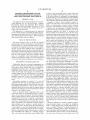
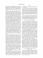
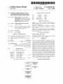
US006802053B1
(12) United States Patent
Dye et al.
(54)
GRAPHICAL PROGRAMMING SYSTEM
WITH DISTRIBUTED BLOCK DIAGRAM
EXECUTION AND FRONT PANEL DISPLAY
(75) Inventors: Robert E. Dye, Austin, TX (US);
Darshan Shah, Round Rock, TX (US);
Steve Rogers, Austin, TX (US); Greg
Richardson, Round Rock, TX (US);
Dean A. Luick, Austin, TX (US)
(73) Assignee: National Instruments Corporation,
Austin, TX (US)
Notice:
US 6,802,053 B1
(10) Patent N0.:
(45) Date of Patent:
Subject to any disclaimer, the term of this
patent is extended or adjusted under 35
U.S.C. 154(b) by 518 days.
(21) Appl. No.: 09/617,600
Jun. 13, 2000
(22) Filed:
Related US. Application Data
Oct. 5, 2004
FOREIGN PATENT DOCUMENTS
EP
EP
EP
W0
W0
W0
0 367 709
0 398 646
0 426 909
W0 94 10627 A
W0 94 15311 A
W0 96 14618 A
5/1990
11/1990
5/1991
5/1994
7/1994
5/1996
OTHER PUBLICATIONS
Shaheen et al., “Remote Laboratory Experimentation”,
IEEE, Proceeding of American Control Conference,
pp.:1326—1329 Jun. 1998*
Gillet et al., “Telepresence: An Opportunity to develop
Real—World Experimentation in Education”, CiteSeer,
pp.:1—6, 1997.*
Johnston et al., “High—Speed Distributed Data Handling for
On—Line Instrumentation Systems”, Lawrence Berkeley
National Laboratory, pp.: 1—19, Aug. 1997.*
(List continued on next page.)
Primary Examiner—Wei Y. Zhen
Assistant Examiner—Ted T. V0
(74) Attorney, Agent, or Firm—Meyertons Hood Kivlin
KoWert & GoetZel, P.C.; Jeffrey C. Hood
(63)
(60)
Continuation-in-part of application No. 08/912,445, ?led on
Aug. 18, 1997, now Pat. No. 6,173,438.
Provisional application No. 60/149,950, ?led on Aug. 19,
1999.
(57)
(51)
(52)
Int. Cl.7 ................................................ .. G06F 9/44
System and method enabling client computer(s) to connect
US. Cl. ..................... .. 717/113; 717/109; 717/127;
to a server Computer and receive a graphical program user
345/740
interface panel(s) for providing input to and/or displaying
(58)
Field of Search ............... .. 717/104_115, 124_131,
Output from the graphical program, thereby Comprising a
717/162_178; 709/217_225; 345/619, 650,
distributed virtual instrumentation system, Wherein a block
734_743, 661, 676, 689, 47()_471, 762_765,
20_24, 965_968
References Cited
diagram executes on a server computer to perform a mea
surement or automation function, and the panel(s) is/are
displayed on the client computer(s), enabling users to
remotely vieW and/or control the function. The user may
U'S' PATENT DOCUMENTS
specify the server, i.e., by entering a URL into a Web broWser
(56)
4,827,404 A
ABSTRACT
and may also specify the graphical program desired. The
user interface panel may be dynamically updated during
5/1989 Barstow et al.
4,849,880 A
7/1989 Bhaskar et al-
execution of the program. The user may interact With the
47901221 A
2/1990 KPdOSkY ct a1~
panel on the client computer to provide input to the graphical
5,109,504 A
4/1992 Little'ton ................... .. 395/500
program executing on the Server, and may also request and
5309556 A
5/1994 Slsmlhch
receive a block diagram for the remote graphical program
5,377,318 A
5,437,464 A
12/1994
Wolber
.
8/1995 Terasima et al. ............ .. 463/43
.
6%" to “W and/0r remotely ed“ the Program"
(List continued on next page.)
162 Claims, 10 Drawing Sheets
_——l
ueer epeptl‘m I lemme ppmwuler
running a graphical program
450
1
user‘: clienl sullwure mail/e: data
updalel lrurrr the 15mm: mprner
Ind updates the user lrrtemrpe
panel(s) an the users
display melt
Q
urer lpeci?el u gl-Iphical prqrlm
running on the rempte wrrrpuler
5:52
ulet pperane: user interface
panel(s) In control the griphical
1
were client mule connects to
the remote computer
m
1
men cllsllt lOMrG rlqlleau me
lrrer lmemim panel ductlpm'orKs)
01th! user interface panel(l)
iiwclited with me ?l'lphiml
awn
iii
1
user‘: cliorlt wltwrrre receive: the
tleer lrrlemrpe panel deucriptloms)
(mm the remote eqmprrler me
d'lspletys the user lmelme panel(s)
an the Ll!!!“ dlaplsy screen
as
nmrarrr
5&2
’
US 6,802,053 B1
Page 2
US. PATENT DOCUMENTS
5,481,740 A
5,497,498 A
5,535,342 A
1/1996 Kodosky
3/1996 Taylor
7/1996 Taylor
5,541,849 A
7/1996 Rostoker et al.
5,555,201 A
9/1996 Dangelo et al.
5,566,295 A
10/1996 Cypher et al. ............ .. 345/326
5,583,749 A
12/1996 Tredennick et al.
5,603,043 A
5,638,299 A
2/1997 Taylor et al.
6/1997 Miller
5,652,875 A
5,652,909 A
7/1997 Taylor
7/1997 Kodosky
5,684,980 A
11/1997 Casselman
5,724,074 A
3/1998 Chainani et al. .......... .. 345/474
5,732,277 A
3/1998 Kodosky et al.
5,737,235 A
4/1998 Kean et al.
5,760,788 A
5,784,275 A
6/1998 Chainani et al. .......... .. 345/475
7/1998 Sojoodi et al. ........... .. 364/191
5,801,689
6,064,409
6,173,438
6,219,628
6,226,776
6,230,307
9/1998
5/2000
1/2001
4/2001
5/2001
5/2001
A
A
B1
B1
B1
B1
Huntsman
Thomsen et al.
Kodosky et al.
Kodosky et al.
Panchul et al.
Davis et al.
OTHER PUBLICATIONS
Weban, A.; BroWn, G. “A Software Development System for
FPGA—based Data Acquisition Systems”, FPGAs for Cus
tom Computing Machines, 1996.
Beguelin et al., “Visualization and Debugging in a Hetero
geneous Environment”, IEEE, Jun. 1993, pp 88—95.
Jamal et al., “The Aplicability of the Visual Programming
Language LabVIEW to Large Real—World Application”,
IEEE, 1995, pp 99—106.
Per—Arne Wiberg, “Graphical Programming of Time—Deter
ministic Real—Time Systems”, IEEE, 1996, pp 173—180.
Ade, M; LauWereins, R; Peperstraete, J .A.; HardWare—Soft
Ware Codesign With GRAPE, Proceedings of the Sixth IEEE
International Workshop on Rapid System Prototyping, Jun.
9, 1995, pp. 40—47.
LauWereins, R; Engels, M; Ade, M; Peperstraete, J;
Grape—II: A System—Level Prototyping Environment for
DSP Applications, Computer, vol. 28, Issue 2, 2/95, pp.
35—43.
Labrosse, Jean, “Inside Real—Time Kernels,” Conference
Proceedings of Embedded Systems Conference East, Mar.
10—12, 1997, Boston, Massachusetts, pp. 205—214.
Labrosse, Jean, “Designing With Real—Time Kernels,” Con
ference Proceedings of Embedded Systems Conference
East, Mar. 10—12, 1997, Boston, Massachusetts, pp.
379—389.
Operating Systems, 2”“ Ed. By Williams Stallings, Prentice
Hall, 1995, “Multiprocessor and Real—Time Scheduling”,
pp. 394—415.
XP000554820 EdWards, et al., “SoftWare acceleration using
programmable hardWare devices,” IEEE Proceedings: Com
puters and Digital Techniques, vol. 143, No. 1, Jan. 1996,
pp. 55—63.
XP000380758 Lesser, et al, “High Level Synthesis and
Generating FPGAs With the BEDROC System,” Journal of
VLSI Signal Processing, vol. 6, No. 2, Aug. 1993, pp.
191—214.
International Search Report for PCT/US 98/13040 mailed
Dec. 22, 1998.
“LabVIEW User Manual for Windows”, National Instru
ments Co., Sep. 1994 pp. 4/1—21.
International Search Report for PCT/US 98/10916 dated
Sep. 17, 1998.
Douglas, Bruce D., Ph.D., Custom Embedded Communica
tion Protocols, Conference Proceedings of Embedded Sys
tems Conference East, Mar. 10—12, 1997, Boston, Massa
chusetts, pp. 637—657.
International Search Report, Application No. PCT/US
00/22317, mailed Dec. 19, 2000.
SPW/CGS Porting Kits Product Data Sheet, 11/94, 2 pages.
MultiProX for SPW Product Data Sheet, 08/94, 4 pages.
DSP ProCoder for SPW Product Data Sheet, 11/94, 4 pages.
Xanalog Corporation Sales Manual, Jan. 1987, 8 pages.
Available XA—1000 Literature and Its Use, 1986, 2 pages.
Xanalog, XA—1000 Programming ICONS, 1986, 26 pages.
Xanalog’s CAE System: The Fastest AT Alive, Mass High
Tech, vol. 4, No. 22, Aug. 1988, 1 page.
Xanalog The Computer Aided Engineering Workstation
Comes to Simulation, Simulation vol. 47, No. 1, Jul. 1986,
3 pages.
Xanalog RT Real Time Analog and Digital I/O, 10/90, 4
pages.
Xanalog/SC+, 9/90, 4 pages.
Xanalog Specializing in Workstations for Continuous
Dynamic Simulation, 1987, 24 pages.
Xanalog Real—Time User Guide, 1994, 28 pages.
Lee et al., “Gabriel: A Design Environment for Program
mable DSPs”, Nov. 7, 1988, 13 pages.
Lee et al., “A Design Tool for HardWare and SoftWare for
Multiprocessor DSP Systems”, May 1989, 4 pages.
Gabriel 0.7 OvervieW, 1990, 5 pages.
Joseph T. Buck and EdWard A. Lee, “Scheduling Dynamic
Data?oW Graphs With Bounded Memory Using the Token
FloW Model”, http://WWW.synopsys.com/, 1995, 4 pages.
EdWard A. Lee, “Design Methodology for DSP”, 1992, 4
pages.
Pino et al, Interface Synthesis in Heterogeneous System—
Level DSP Design Tools, May 1996, 4 pages.
Jose Luis Pino, Master’s Report, “SoftWare Synthesis for
Single—Processor DSP Systems Using Ptolemy”, May 1993,
48 pages.
AsaWaree Kalavade and EdWard A. Lee, “A HardWare—Soft
Shearman, Sam, Assoc. Editor, “HardWare—in—the—loop
connectivity extends continuous—system simulation”, Per
Ware Codesign Methodology for DSP Applications”, 1993,
sonal Engineering, Jun. 1997, pp. 18—37.
XP0002087124 Xiao—Yu, et al., “SotWare Environment for
Pino et al., “Automatic Code Generation for Heterogeneous
WASMII: AData Driven Machine With a Virtual HardWare,”
Tool Chest continues to GroW, Electronic Engineering
Times, Dec. 15, 1995, 2 pages.
Field Programmable Logic Architectures, Synthesis and
Applications, 4”1 International Workshop on Field—Program
mable Logic and Applications, FPL ’94 Proceedings, Berlin,
Germany, 1994.
12 pages.
Multiprocessors”, 1994, 4 pages.
Pino et al., Mapping Multiple Independent Syunchronous
data?oW Graphs onto Heterogeneous Multiprocessors, Oct.
1994, 6 pages.
US 6,802,053 B1
Page 3
Asawaree Kalavade and Edward A. Lee, Hardware/Software
Collamati et al. “Induction Machine stator Fault On—line
Co—Design Using Ptolemy—A Case Study, 09/1992, 18
Diagnosis Based on LabVIEW Environment”, Mediterra
nean Electrotechnical Conference, vol. 1, p. 495—498, May
pages.
Pino et al, “Software Synthesis for DSP Using Ptolemy”,
1995, 15 pages.
vol. 1—Ptolemy 0.7 User’s Manual, 1997, 532 pages.
i—LogiX Product Overview, 1996, 52 pages.
Press Release, i—LogiX Statement MAGNUM Supports PCs,
Jan. 31, 1997, 2 pages.
Press Release, i—IJogiX Signs Reseller Agreement for Virtual
Prototypes, Inc.’s VAPS Product Line, Feb. 11, 1997, 2
pages.
Press Release, “i—LogiX Introduces Rhapsody, Object—Ori
ented analysis, Design and Implementation Tool”, Feb. 10,
1997, 2 pages.
Statement/C Product Overview, 1995, 4 pages.
Press Release, “i—LogiX and Integrated Systems Link
Statemate MAGNUM and MATRIX AutoCode” Jan. 03,
1997, 2 pages.
Press Release, i—LogiX and Wind River unveil Industry’s
First Rapid Prototyping Solution for Testing Embedded
Systems at ESC West in San Jose, Sep. 17, 1996, 3 pages.
Press Release, i—LogiX Inc. Endorses Uni?ed Modeling
Language, Jan. 16, 1997, 1 page.
Philip Dean Lapsley, “Host Interface and Debugging of
Data?ow DSP Systems”, Thesis, 1991, pp. 1—51.
Lee et al., “Gabriel: A Design Environment for Program
mable DSPs”, 1988, pp. 1—11.
Lee et al., “Gabriel: ADesign Environment for DSP”, IEEE
Transactions on Acoustics, Speech, and Signal Processing,
vol. 37, No. 11, Nov. 1989, pp. 1751—1762.
Bier et al., “Gabriel: A Design Environment for DSP”, IEEE
Micro Issue—vol. 10, No. 5, 1990, pp. 28—45.
Ludolph et al., “The Fabrik Programming Environment”,
IEEE, pp. 222—230, 1988.
De Coster, GRAPE—II: An Introduction [online]. Automatic
Control and Computer Architectures Department. Katho
lieke Universiteit Leuven, Belgium, Feb. 22, 1996 [retrieved
Oct. 6, 1999] Retreived from the Internet @ http://www.e
sat.kuleuven.ac.be/acca.
1996.
Spoelder et al., “Virtual Instrumentation: A Survey of Stan
dards and Their Interrelation”, Proc. IEEE Instr. and Mea
surement Tech. Conf., vol. 1, pp. 676—681, May 1997.
Srinivasan et al., “LabVIEW program Design for On—Line
Data Acquisition and Predictive Maintenance”, Proc. Of the
30th Southeastern Symp. On System Theory, pp. 520—524,
Mar. 1998.
Wahidanabanu et al., “Virtual Instrumentation with Graphi
cal Programming for Enhanced Detection and Monitoring of
Partial Discharges”, Proc. Electrical Insulation Conf. 1997,
pp. 291—296, Sep. 1997.
Choosing Block—Diagram Tools for DSP Design, http://
www.bdti.com/articles/info
dspmt95blockdiagram.htm,
May 9, 2003, pp. 1—7.
Real—Time Workshop for Use with Simulink, User’s Guide,
May 1994, 229 pages.
Guide to Rapid Prototyping with Simulink, Real—Time
Workshop and dSPACE, 1995, 16 pages.
Real—Time Interface to Simulink, RTI 30, User’s Guide,
1995, 125 pages.
Kevin J Gorman and Kourosh J. Rahnamai, “Real—Time
Data Acquisition and Controls Using MatLAB”, 1995, 4
pages.
SPW—MatLAB Co—Simulation Interface Product Data
Sheet, 1996, 2 pages.
Signal Processing WorkSystem, MatLAB Interface User’s
Guide, Oct. 1995, 72 pages.
Alta Group of Cadence Design Systems, Inc., 1995, 34
pages.
Code Generation System Product Data Sheet, 1994, 8 pages.
* cited by examiner
U.S. Patent
0a. 5,2004
Sheet 1 0f 10
2252
0
U2:2H/ BES9Q6
US 6,802,053 B1
on
225wa3gs mm
E2Q93
Q
U.S. Patent
0a. 5,2004
$5-8
uowmESaBQE
Sheet 2 0f 10
g“2a0mcing
US 6,802,053 B1
02
U.S. Patent
0a. 5,2004
Sheet 3 0f 10
US 6,802,053 B1
.OEmm
\(8.
2: 5 E80
5
xvii
9£4(58a2
U.S. Patent
0a. 5,2004
Sheet 5 0f 10
US 6,802,053 B1
user creates or edits a user
interface panel for controls
and indicators
5L0.
l
user adds objects, edits objects, and!
or connects objects
of the graphical program, such as
functional blocks and programmatic
structures, etc.
5.2.2
l
user saves or runs the
graphical program
QQ
FIG. 4
U.S. Patent
0a. 5,2004
Sheet 6 0f 10
Emu-pl Hi
US 6,802,053 B1
Ml
fl: _E_dit Qpetale Eroiect \lindows Help
2 P
The Iesul 0! 2.0 +3.0 was:
BIT-I
FIG. 5
E E lcample1 .vi D iagran
_. [Elli]
‘ Eila Edit Qpetale Eroiecl window: Help
a
,
@@El§l@?~EIIEI
l;
LIP
The result of 20 + 3.0 was:
I|>— [an
?
4|
I
FIG. 6
ill/i
U.S. Patent
0a. 5, 2004
user speci?es a remote computer
running a graphical program
i5_0
Sheet 7 0f 10
US 6,802,053 B1
user's client software receives data
updates from the remote computer
and updates the user interface
panel(s) on the user's
display screen
4_60.
user speci?es a graphical program
running on the remote computer
£2
user operates user interface
panel(s) to control the graphical
program
52
user's client software connects to
the remote computer
454
I
user's client software requests the
user interface panel description(s)
of the user interface panel(s)
associated with the graphical
program
4.5.5.
user's client software receives the
user interface panel description(s)
from the remote computer and
displays the user interface panel(s)
on the user's display screen
4_5_§
l_____
FIG. 7
U.S. Patent
0a. 5,2004
Sheet 8 0f 10
US 6,802,053 B1
HighLwelL'niHlbm)
‘ LouLevelUmlUbm)
nynmmi?das?
LaITempUnmdq F)
Continue monitoring the tank until
Power bdlon is pushed
FIG. 8B
US 6,802,053 B1
1
2
GRAPHICAL PROGRAMMING SYSTEM
WITH DISTRIBUTED BLOCK DIAGRAM
EXECUTION AND FRONT PANEL DISPLAY
in order to both conceptually model a system and then to
program a computer to model that system. Since a user often
is not fully pro?cient in techniques for programming a
computer system in a text-based environment to implement
his model, the ef?ciency With Which the computer system
PRIORITY CLAIM
This application claims bene?t of priority of US. provi
sional application Ser. No. 60/149,950 titled “Graphical
Programming System With Distributed Block Diagram
Execution and Front Panel Display” ?led Aug. 19, 1999,
Whose inventors Were Robert Dye, Darshan Shah, Steve
can be utiliZed to perform such modeling often is reduced.
Examples of ?elds in Which computer systems are
employed to model and/or control physical systems are the
10
of devices such as instruments or industrial automation
Rogers, and Greg Richardson.
This application is a continuation-in-part of application
Ser. No. 08/912,445 titled “Embedded Graphical Program
ming System” and ?led on Aug. 18, 1997 now US. Pat. No.
6,173,438, Whose inventors are Jeffrey L. Kodosky, Darshan
?elds of instrumentation, process control, industrial
automation, and simulation. Computer modeling or control
hardWare has become increasingly desirable in vieW of the
increasing complexity and variety of instruments and
devices available for use. HoWever, due to the Wide variety
15
of possible testing/control situations and environments, and
also the Wide array of instruments or devices available, it is
Shah, Samson DeKey, and Steve Rogers.
often necessary for a user to develop a program to control a
desired system. As discussed above, computer programs
FIELD OF THE INVENTION
The present invention relates to the ?eld of graphical
programming and virtual instrumentation. In particular, the
used to control such systems had to be Written in conven
20
example, assembly language, C, FORTRAN, BASIC, or
Pascal. Traditional users of these systems, hoWever, often
invention relates to a system and method Wherein a graphi
cal program block diagram executes on a server computer,
and one or more client computers receive and display a
graphical program user interface panel corresponding to the
block diagram, Wherein the graphical program user interface
panel can be used to provide input to or display output to
from the block diagram. The present invention further
Were not highly trained in programming techniques and, in
addition, traditional text-based programming languages
25 Were not sufficiently intuitive to alloW users to use these
languages Without training. Therefore, implementation of
relates to a distributed virtual instrumentation system,
Wherein a block diagram executes on a server computer and 30
one or more front panels are displayed on client computers.
Traditionally, high level text-based programming lan
35
FORTRAN, Pascal, COBOL, ADA, APL, etc. Programs
machine language level by translators knoWn as compilers
or interpreters. The high level text-based programming
languages in this level, as Well as the assembly language
40
a graphical programming environment, Which enables a user
environment can be represented at a level above text-based
high level programming languages such as C, Pascal, etc.
The method disclosed in Kodosky et al alloWs a user to
level, are referred to as text-based programming environ
ments.
US. Pat. Nos. 4,901,221; 4,914,568; 5,291,587; 5,301,
to easily and intuitively model a process. The graphical
programming environment disclosed in Kodosky et al can be
considered the highest and most intuitive Way in Which to
interact With a computer. A graphically based programming
gramming languages exist, including BASIC, C,
Written in these high level languages are translated to the
such systems frequently required the involvement of a
programmer to Write softWare for control and analysis of
instrumentation or industrial automation data. Thus, devel
opment and maintenance of the softWare elements in these
systems often proved to be dif?cult.
301; and 5,301,336; among others, to Kodosky et al disclose
a graphical system and method for modeling a process, i.e.,
DESCRIPTION OF THE RELATED ART
guages have been used by programmers in Writing applica
tion programs. Many different high level text-based pro
tional text-based programming languages such as, for
45
Increasingly, computers are required to be used and
programmed by those Who are not highly trained in com
construct a diagram using a block diagram editor, such that
the diagram created graphically displays a procedure or
method for accomplishing a certain result, such as manipu
lating one or more input variables to produce one or more
output variables. In response to the user constructing a data
puter programming techniques. When traditional text-based
How diagram or graphical program using the block diagram
editor, data structures may be automatically constructed
programming environments are used, the user’s program
ming skills and ability to interact With the computer system
often become a limiting factor in the achievement of optimal
utiliZation of the computer system.
Which characteriZe an execution procedure Which corre
sponds to the displayed procedure. The graphical program
may be compiled or interpreted by a computer using these
data structures. Therefore, a user can create a computer
There are numerous subtle complexities Which a user
program solely by using a graphically based programming
must master before he can ef?ciently program a computer
system in a text-based environment. The task of program 55 environment. This graphically based programming environ
ment may be used for creating virtual instrumentation
ming a computer system to model a process often is further
complicated by the fact that a sequence of mathematical
formulas, mathematical steps or other procedures custom
arily used to conceptually model a process often does not
closely correspond to the traditional text-based program
ming techniques used to program a computer system to
model such a process. In other Words, the requirement that
a user program in a text-based programming environment
systems, industrial automation systems, modeling processes,
and simulation, as Well as for any type of general program
ming.
60
Therefore, Kodosky et al teaches a graphical program
ming environment Wherein a user places or manipulates
icons in a block diagram using a block diagram editor to
create a graphical “program.” A graphical program for
controlling or modeling devices, such as instruments, pro
places a level of abstraction betWeen the user’s conceptu
aliZation of the solution and the implementation of a method
that accomplishes this solution in a computer program.
65 cesses or industrial automation hardWare, is referred to as a
Thus, a user often must substantially master different skills
user may create a front panel or user interface panel. The
virtual instrument (VI). In creating a virtual instrument, a
US 6,802,053 B1
3
4
front panel includes various front panel objects, such as
controls or indicators, that represent or display the respective
input and output that Will be used by the graphical program
having various types of user interface panels to export their
user interface panels as described above, With a minimal
amount of programming effort. It may also be desirable to
or VI, and may include other icons Which represent devices
being controlled. When the controls and indicators are
created in the front panel, corresponding icons or terminals
provide the above capabilities using common netWorking
and softWare standards so that users Working on various
types of computing platforms could connect to the remote
computer running the graphical program, vieW the user
may be automatically created in the block diagram by the
block diagram editor. Alternatively, the user can place
terminal icons or input/output blocks in the block diagram
Which may cause the display of corresponding front panel
objects in the front panel, either at edit time or at run time.
interface panel of the graphical program, and possibly also
use the user interface panel to remotely use or control the
10
During creation of the graphical program, the user selects
various functions that accomplish his desired result and
connects the function icons together. For example, the
functions may be connected in a data How and/or control
How format. The functions may be connected betWeen the
gain these abilities, and/or to enable the necessary client
softWare to be automatically doWnloaded and installed.
SUMMARY OF THE INVENTION
15
terminals of the respective controls and indicators. For
The problems outlined above may in large part be solved
by providing a system and method enabling distributed
example, the user may create or assemble a data How
program, referred to as a block diagram, representing the
display of the user interface of a graphical program execut
ing on a server computer. In one embodiment, the system
graphical data flow which accomplishes his desired func
tion. The assembled graphical program may then be com
includes a server computer Where a graphical program
executes, and one or more client computers connected to the
server computer Which receive and display a user interface,
e.g., one or more user interface panels, corresponding to the
piled or interpreted to produce machine language that
accomplishes the desired method or process as shoWn in the
block diagram.
A user may input data to a virtual instrument using front
panel controls. This input data propagates through the data
graphical program. It may also be desirable to require users
to install a minimal amount of client softWare in order to
25
graphical program. In one embodiment, the user interface
panel of an instrument. In an industrial automation applica
can be used from the client computer(s) to provide input to
or display output from the graphical program during pro
gram execution. In one speci?c embodiment, the invention
may comprise a distributed virtual instrumentation system,
tion the front panel can be analogiZed to the MMI (Man
Machine Interface) of a device. The user may adjust the
Wherein a graphical program executes on a server computer
to perform a measurement or automation function, and one
controls on the front panel to affect the input and vieW the
output on the respective indicators. Alternatively, the front
panel may be used merely to vieW the input and output, and
the input may not be interactively manipulable by the user
during program execution.
or more front panels are displayed on client computers, thus
enabling one or more users to remotely vieW and/or control
How block diagram or graphical program and appears as
changes on the output indicators. In an instrumentation
application, the front panel can be analogiZed to the front
the measurement or automation function.
35
In one embodiment, a user of a client computer speci?es
a remote server computer on Which a graphical program
executes. The remote server information may be speci?ed in
Thus, graphical programming has become a poWerful tool
available to programmers. Graphical programming environ
various Ways. For example, the information may be speci
ments such as the National Instruments LabVIEW product
have become very popular. Tools such as LabVIEW have
protocol (IP) address, as a machine name and TCP/IP port
?ed as a uniform resource locator (URL), as an internet
40
number, etc. In one embodiment, a user may specify the
greatly increased the productivity of programmers, and
increasing numbers of programmers are using graphical
programming environments to develop their softWare appli
cations. In particular, graphical programming tools are being
used for test and measurement, data acquisition, process
remote computer by entering a URL into an application such
as a Web broWser or other application With Web-broWsing
functionality. As described beloW, the application may
45
include a protocol handler plug-in enabled to process the
control, man machine interface (MMI), supervisory control
URL and connect to the remote computer.
and data acquisition (SCADA) applications, simulation, and
When the user speci?es the remote computer running the
graphical program, the user may also specify the particular
graphical program desired. For example, a parameter indi
cating the name of the graphical program may be appended
machine vision applications, among others.
In many scenarios, it Would be desirable to further sepa
rate the user interface panel, also referred to above as the
front panel, of a graphical program from the block diagram
to the URL, etc. The user may also specify the remote
of the graphical program. For example, a user developing an
computer Without also specifying the particular graphical
instrumentation application, such as a test and measurement
program. For example, the remote computer may comprise
application or a process control application, may desire the
a Web server. The user may enter the URL of a Web page
graphical program to execute on a computer located in a 55 associated With the Web server, and the Web server may
return a list of graphical programs running on the remote
laboratory or manufacturing facility, but may Want to inter
act With the program by vieWing the program’s user inter
computer. The user may then select one or more graphical
programs from this list. The user’s client softWare is oper
able to then display the user interface panels associated With
face panel from another computer, such as a Workstation
located in the user’s office. As another example, a program
developer may construct a graphical program and desire to
enable others to interact With or vieW the results of the
the selected graphical program(s) on the user’s display
screen.
program. For example, the program developer may desire to
In one embodiment, the user’s client softWare comprises
enable multiple Internet users to connect to the computer
a Web broWser (or application With Web-broWsing
functionality) With a plug-in operable to communicate With
running the graphical program and vieW the graphical pro
gram’s user interface.
It Would thus be desirable to provide a general system and
method for enabling various types of graphical programs
65
the remote graphical program. In this embodiment, the
plug-in may display the user interface panel directly in the
Web broWser’s WindoW. The user’s client softWare prefer
US 6,802,053 B1
5
6
ably communicates With an agent or software program
running on the remote computer using a communication
FIG. 1 illustrates a computer system connected through a
netWork to a second computer system;
protocol based on the standard TCP/IP protocol. When the
FIGS. 2A and 2B illustrate representative instrumentation
and process control systems including various I/O interface
user speci?es the remote computer for a connection, the
agent on the remote computer transfers a description of the
options;
graphical program’s user interface panel to the user’s client
FIG. 3 is a block diagram of the computer system of
softWare. This description may be sent in the same format
used to store the user interface panel information on the
FIGS. 1, 2A and 2B;
FIG. 4 is a ?oWchart diagram illustrating one embodiment
remote computer. The user interface panel description may,
of course, be sent in various other formats, e.g., as an XML
of interactively creating or editing a graphical program;
10
description. The user’s client-side softWare, e.g., Web
broWser plug-in, is preferably enabled to interpret any type
of user interface panel description that it may receive from
the remote computer, and is enabled to appropriately display
the user interface panel to the user.
of a user accessing a remote graphical program.
15
received and displayed on the user’s display screen, the user
interface panel may be dynamically updated during execu
tion of the graphical program block diagram. For example,
20
25
Incorporation by Reference
30
US. patent application Ser. No. 08/912,445 titled
“Embedded Graphical Programming System” ?led Aug. 18,
In other Words, the user may interact With the remote
1997 now US. Pat. No. 6,173,438.
35
means for coordinating control among users may be
included so that multiple users interacting With the same
US. patent application Ser. No. 08/916,005 titled “Sys
40
request and receive the remote graphical program’s block
diagram, e.g., to edit or debug the graphical program.
As noted above, in the preferred embodiment, a TCP/IP
based communication protocol is used for communication
US. patent application Ser. No. 09/136,123 titled “Sys
computer executing the graphical program. In an alternative
embodiment the DataSocket system and method, disclosed
in US. patent application Ser. No. 09/185,161 now US. Pat.
US. patent application Ser. No. 09/518,492 titled “Sys
tem and Method for Programmatically Creating a Graphical
Program” ?led Mar. 3, 2000.
US. patent application Ser. No. 09/185,161 titled “Data
Socket System and Method for Accessing Data Sources
Using URLs” ?led Nov. 3, 1998 now US. Pat. No. 6,370,
running the graphical program. The DataSocket system
569, Whose inventor Was Paul F. Austin.
55
US. patent application Ser. No. 09/374,740 titled “Sys
tem and Method for Automatically Creating URLs for
Accessing Data Sources and Data Targets” ?led Aug. 13,
1999, Whose inventors Were Paul Austin, David Fuller, Kurt
M. Carlson, Chris Mayer, Stephen Rogers, Joe Savage, and
functionality may be used to enable user clients to connect
to and interact With a remote graphical program. For more
Brian Sierer.
60
cations incorporated by reference beloW.
US. patent application Ser. No. 09/546,047 titled “Sys
tem and Method for Connecting to and VieWing Live Data
using a Standard User Agent” ?led Apr. 10, 2000, Whose
BRIEF DESCRIPTION OF THE DRAWINGS
inventor Was Paul Austin.
A better understanding of the present invention can be
folloWing draWings, in Which:
tem and Method for Accessing Object Capabilities in a
Graphical Program” ?led Aug. 18, 1998 now US. Pat. No.
6,437,805.
No. 6,370,569, may be used to facilitate the communication
betWeen the user’s client softWare and the remote computer
obtained When the folloWing detailed description of the
preferred embodiment is considered in conjunction With the
tem and Method for Providing Client/Server Access to
Graphical Programs” ?led Aug. 21, 1997 now US. Pat. No.
6,102,965.
betWeen the user’s client softWare and the remote server 45
information on VI Server, please refer to the patent appli
US. patent application Ser. No. 08/810,079 titled “Sys
tem and Method for Developing Automation Clients Using
a Graphical Data FloW Program” ?led Mar. 4, 1997 now
US. Pat. No. 6,064,812.
graphical program do not interfere With each others’ actions.
comprises a client softWare component that addresses data
sources/targets using a URL, much the Way that a URL is
used to address Web pages anyWhere in the World.
In one embodiment, the remote graphical program
executes Within a graphical programming environment
including functionality referred to as “VI Server”. VI Server
The folloWing references are hereby incorporated by
reference in their entirety as though fully and completely set
forth herein.
computer, and the graphical program responds accordingly.
As described beloW, in one embodiment, a user may also
trary the invention is to cover all modi?cations, equivalents
and alternative folloWing Within the spirit and scope of the
present invention as de?ned by the appended claims.
DETAILED DESCRIPTION OF THE
PREFERRED EMBODIMENTS
passed to the remote graphical program on the server
graphical program exactly as he Would interact With the
program if it Were running locally on the user’s computer. A
by Way of example in the draWings and are herein described
in detail. It should be understood hoWever, that draWings and
detailed description thereto are not intended to limit the
invention to the particular form disclosed. But on the con
The user may also interact With the user interface panel on
the client computer to provide input to the block diagram
executing on the server computer, eg by issuing standard
point-and-click type GUI commands. The user’s input is
FIGS. 8A—8B, 9A—9B, 10A—10B illustrate exemplary
graphical programs and their associated user interfaces.
While the invention is susceptible to various modi?ca
tions and alternative forms speci?c embodiments are shoWn
Once the graphical program’s user interface panel is
the user interface panel may include a graph Which displays
various types of measurement data produced by the block
diagram, such as an electrical signal, meteorological data,
etc., and this graph may scroll on the user’s display as the
measured data values change in response to graphical pro
gram execution. As another example, the user interface
panel may comprise numerical text indicators that are
updated With neW values periodically, etc.
FIG. 5 and 6 illustrate a simple graphical program com
prising a user interface panel and a block diagram; and
FIG. 7 is a ?oWchart diagram illustrating one embodiment
65
FIG. 1—Computer System Connected to a NetWork
FIG. 1 illustrates an exemplary computer netWork in
Which a computer system 82 is connected through a netWork
US 6,802,053 B1
7
8
84 to a second computer system 86. The computer system 82
and the second computer system 86 can be any of various
acquisition board 114 and associated signal conditioning
circuitry 124, a VXI instrument 116, a PXI instrument 118,
a video device 132 and associated image acquisition card
134, a motion control device 136 and associated motion
types, as desired. The netWork 84 can also be any of various
types, including a LAN (local area network), WAN (Wide
area network), or the Internet, among others.
A user of computer system 82 may connect to computer
control interface card 138, and/or one or more computer
based instrument cards 142, among other types of devices.
The GPIB instrument 112 is coupled to the computer 86
via the GPIB interface card 122 provided by the computer
system 86, according to the system and method described
herein. Computer system 82, Which may be referred to as
client computer system 82, comprises client softWare
enabled to receive a description of a graphical program user
86. In a similar manner, the video device 132 is coupled to
10
interface panel and display the panel on the display screen
of computer system 82. For example the client softWare may
motion control device 136 is coupled to the computer 86
through the motion control interface card 138. The data
acquisition board 114 is coupled to the computer 86, and
comprise a Web broWser With a Web broWser plug-in. For
example, the Web broWser may be the Microsoft Internet
Explorer Web broWser, and the plug-in may be constructed
the computer 86 via the image acquisition card 134, and the
15
according to Microsoft’sAsynchronous Pluggable Protocols
may interface through signal conditioning circuitry 124 to
the UUT. The signal conditioning circuitry 124 preferably
comprises an SCXI (Signal Conditioning eXtensions for
speci?cation.
Instrumentation) chassis comprising one or more SCXI
Computer system 86, Which may be referred to as server
modules 126.
computer system 86, comprises a graphical program, as Well
The GPIB card 122, the image acquisition card 134, the
as server-side programs or agents enabling the user of
computer system 82 to communicate With computer system
86 according to the present invention. For example, com
puter system 86 may include VI Server functionality, as
discussed above.
Although, only one client is shoWn connected to computer
system 86, as described above, multiple clients may connect
to computer 86 in order to vieW the graphical program’s user
motion control interface card 138, and the DAQ card 114 are
typically plugged in to an I/O slot in the computer 86, such
as a PCI bus slot, a PC Card slot, or an ISA, EISA or
MicroChannel bus slot provided by the computer 86.
25
The VXI chassis or instrument 116 is coupled to the
computer 86 via a VXI bus, MXI bus, or other serial or
interface panel and/or interact With the graphical program.
Computer system 86 preferably includes a mechanism for
coordinating control of the graphical program among mul
tiple remote users. For example, computer system 86 may
parallel bus provided by the computer 86. The computer 86
preferably includes VXI interface logic, such as a VXI, MXI
or GPIB interface card (not shoWn), Which interfaces to the
VXI chassis 116. The PXI chassis or instrument is preferably
distribute control of the graphical program among the users
coupled to the computer 86 through the computer’s PCI bus.
A serial instrument (not shoWn) may also be coupled to
using various methods or algorithms, such as a round-robin
scheme, prioritiZed round-robin scheme, etc. Various types
of privileges or permissions may be assigned to different
35
users, granting them different levels of control over the
the computer 86 through a serial port, such as an RS-232
port, USB (Universal Serial bus) or IEEE 1394 or 1394.2
bus, provided by the computer 86. In typical instrumentation
graphical program. For example, the program creator may
40
control systems an instrument Will not be present of each
interface type, and in fact many systems may only have one
or more instruments of a single interface type, such as only
GPIB instruments.
The instruments are coupled to the unit under test (UUT)
or process 150, or are coupled to receive ?eld signals,
45
used in a data acquisition and control application, in a test
and measurement application, a process control application,
be authoriZed to assume complete control over the program,
locking out other users. Other users may only be authoriZed
to vieW the graphical program’s user interface panel, but not
HoWever, these cards 122, 134, 138 and 114 are shoWn
external to computer 86 for illustrative purposes.
to use it to control the graphical program, e.g., these users
may not be alloWed to provide input to the graphical
program.
typically generated by transducers. The system 100 may be
FIGS. 2A and 2B—Instrumentation and Industrial
Automation Systems
FIGS. 2A and 2B illustrate exemplary systems that may
or a man-machine interface application.
store or use programs according to the present invention.
These exemplary systems illustrate systems specialiZed for
FIG. 2B illustrates an exemplary industrial automation
system 160. The industrial automation system 160 is similar
instrumentation, process control, or other purposes. FIGS.
2A and 2B illustrate exemplary server computer systems.
Thus, the server computer 86 described above may be
to the instrumentation or test and measurement system 100
shoWn in FIG. 2A. Elements Which are similar or identical
to elements in FIG. 2A have the same reference numerals for
comprised in an instrumentation or industrial automation
convenience. The system 160 comprises a computer 86
system, Wherein the present invention alloWs for distributed
Which connects to one or more devices or instruments. The
control of a test or automation application. The present
invention may of course be used in other types of applica
55
computer 86 comprises a CPU, a display screen, memory,
and one or more input devices such as a mouse or keyboard
tions as desired.
as shoWn. The computer 86 connects through the one or
FIG. 2A illustrates an instrumentation control system 100.
more devices to a process or device 150 to perform an
The system 100 comprises a host computer 86 (server
automation function, such as MMI (Man Machine
computer 86) Which connects to one or more instruments.
The host computer 86 comprises a CPU, a display screen,
Interface), SCADA (Supervisory Control and Data
Acquisition), portable or distributed data acquisition, pro
memory, and one or more input devices such as a mouse or
cess control, advanced analysis, or other control.
keyboard as shoWn. The computer 86 connects through the
The one or more devices may include a data acquisition
one or more instruments to analyZe, measure, or control a
board 114 and associated signal conditioning circuitry 124,
unit under test (UUT) or process 150.
The one or more instruments may include a GPIB instru
ment 112 and associated GPIB interface card 122, a data
65
a PXI instrument 118, a video device 132 and associated
image acquisition card 134, a motion control device 136 and
associated motion control interface card 138, a ?eldbus
US 6,802,053 B1
9
10
device 170 and associated ?eldbus interface card 172, a PLC
specialiZed broWser plug-in for communicating With the
(Programmable Logic Controller) 176, a serial instrument
server computer.
182 and associated serial interface card 184, or a distributed
In one embodiment, the graphical program that users may
remotely vieW or control is a program for data acquisition/
data acquisition system, such as the Fieldpoint system
available from National Instruments, among other types of
generation, analysis, and/or display, or for controlling or
devices.
The DAQ card 114, the PXI chassis 118, the video device
Ware. For example, in the preferred embodiment, the graphi
modeling instrumentation or industrial automation hard
132, and the image acquisition card 136 are preferably
cal program is a program constructed using the National
connected to the computer 86 as described above. The serial
Instruments LabVIEW graphical programming environment
application, Which provides specialiZed support for devel
instrument 182 is coupled to the computer 86 through a
10
serial interface card 184, or through a serial port, such as an
RS-232 port, provided by the computer 86. The PLC 176
couples to the computer 86 through a serial port, Ethernet
port, or a proprietary interface. The ?eldbus interface card
172 is preferably comprised in the computer 86 and inter
15
faces through a ?eldbus netWork to one or more ?eldbus
devices. Each of the DAQ card 114, the serial card 184, the
remotely interact With graphical programs for any of various
types of purposes in any of various applications.
?eldbus card 172, the image acquisition card 134, and the
motion control card 138 are typically plugged in to an I/O
slot in the computer 86 as described above. HoWever, these
FIG. 3—Computer System Block Diagram
cards 114, 184, 172, 134, and 138 are shoWn external to
computer 86 for illustrative purposes. In typical industrial
automation systems a device Will not be present of each
interface type, and in fact many systems may only have one
or more devices of a single interface type, such as only 25
PLCs. The devices are coupled to the device or process 150.
Referring again to FIGS. 2A and 2B, the server computer
one or more computer programs or softWare components
according to the present invention are stored. The term
“memory medium” is intended to include an installation
present invention have been omitted for simplicity.
The computer 86 (or 82) includes at least one central
medium, e.g., a CD-ROM, ?oppy disks 104, or tape device,
a computer system memory or random access memory such
35
processing unit or CPU 160 Which is coupled to a processor
or host bus 162. The CPU 160 may be any of various types,
including an x86 processor, e. g., a Pentium class, a PoWerPC
40
latter instance, the second computer provides the program
instructions to the ?rst computer for execution. The server 45
computer system 86 may take any of various forms. In a
similar manner, the client computer system 82 may take any
of various forms, including a personal computer system,
processor, a CPU from the SPARC family of RISC
processors, as Well as others. Main memory 166 is coupled
to the host bus 162 by means of memory controller 164.
The main memory 166 stores computer programs accord
ing to the present invention. The main memory 166 also
stores operating system softWare as Well as the softWare for
operation of the computer system, as Well knoWn to those
skilled in the art. The computer programs of the present
invention Will be discussed in more detail beloW.
The host bus 162 is coupled to an expansion or input/
output bus 170 by means of a bus controller 168 or bus
bridge logic. The expansion bus 170 is preferably the PCI
Workstation, netWork appliance, Internet appliance, personal
(Peripheral Component Interconnect) expansion bus,
digital assistant (PDA), television system or other device. In
general, the term “computer system” can be broadly de?ned
to encompass any device having at least one processor
Which executes instructions from a memory medium.
In one embodiment, the memory medium of the server
computer 86 stores softWare programs for communicating
With the client computer system 82, according to the present
invention. For example, the server computer 86 may store
netWork communication softWare, e.g., TCP/IP softWare,
FIG. 3 is a block diagram of the computer system illus
trated in FIGS. 1, 2A and 2B. It is noted that any type of
computer system con?guration or architecture can be used
as desired, and FIG. 3 illustrates a representative PC
embodiment. It is also noted that the computer system may
be a general purpose computer system as shoWn in FIGS. 2A
and 2B, a computer implemented on a VXI card installed in
a VXI chassis, a computer implemented on a PXI card
installed in a PXI chassis, or other types of embodiments.
The elements of a computer not necessary to understand the
system 86 preferably includes a memory medium on Which
as DRAM, SRAM, EDO RAM, Rambus RAM, etc., or a
non-volatile memory such as a magnetic media, e.g., a hard
drive, or optical storage. The memory medium may com
prise other types of memory as Well, or combinations
thereof.
In addition, the memory medium may be located in a ?rst
computer in Which the programs are executed, or may be
located in a second different computer Which connects to the
?rst computer over a netWork, such as the Internet. In the
opers of instrumentation and industrial automation applica
tions.
HoWever, it is noted that the present invention can be used
for a plethora of applications and is not limited to instru
mentation or industrial automation applications. In other
Words, FIGS. 2A and 2B are exemplary only, and users may
55
although other bus types can be used. The expansion bus 170
includes slots for various devices such as the data acquisi
tion board 114 (of FIG. 2A), a GPIB interface card 122
Which provides a GPIB bus interface to the GPIB instrument
112 (of FIG. 2A), and a VXI or MXI bus card 186 coupled
to the VXI chassis 116 for receiving VXI instruments. The
computer 86 further comprises a video display subsystem
180 and hard drive 182 coupled to the expansion bus 170.
and may also store application-level softWare, such as a
FIGS. 4—6: Interactive Creation of a Graphical
graphical programming system enabled to communicate
Program by a User
With remote computers.
In one embodiment, the memory medium of the client
computer 82 stores softWare programs for communicating
of hoW a user may interactively or manually create or edit a
FIG. 4 is a ?oWchart diagram illustrating one embodiment
standard user agent, such as a Web broWser or other appli
graphical program. As shoWn in the ?oWchart and described
beloW, the user interactively adds various objects to a
graphical program, connects them together, etc. It is noted
that the various steps of FIG. 4 may be performed in various
cation With Web-broWsing functionality, and possibly a
orders, or omitted as desired.
With the server computer system 86, according to the present
invention. For example, the client computer 82 may store a
65
US 6,802,053 B1
11
12
example the objects may include input and output terminals,
In the embodiment shown in FIG. 4, the steps are per
formed by a developer creating or editing a graphical
program in a graphical programming environment. As
and the developer may connect the output terminal of one
node to the input terminal of another node, etc. FIG. 6
shoWn, in step 420 the developer may create or edit a user
illustrates one embodiment of hoW objects may be con
interface panel for displaying a graphical user interface. The
user interface panel may comprise controls for accepting
user input, displaying information such as program output,
or both. For example, the user interface panel may include
nected. In this example, output terminals of the tWo numeric
constant nodes are connected to the input terminals of an
addition function node. The addition function node performs
the addition operation on the numeric input. The output
buttons, selectable lists, text boxes, graph controls, images,
etc. A developer may “drop” various controls or other
objects onto the user interface panel, e.g., by selecting the
10
the addition operation is displayed in the user interface panel
desired control from a control palette. FIG. 5 illustrates a
shoWn in FIG. 5.
simple user interface panel. Step 420 is not necessarily
performed. For example, a user interface panel may not be
desired, a user interface panel may be inherently speci?ed
during creation of the block diagram, or a user interface
panel may automatically be created as the user creates the
15
a condition terminal to Which an output terminal of a node
When the loop should end.
For more information on one embodiment of creating or
20
diagram comprising objects referred to herein as “nodes”
Which are connected together to model the program execu
25
functionality of the node. FIG. 6 illustrates a simple block
diagram. As a developer adds objects to the user interface
In step 426 of FIG. 4, the developer saves or runs the
graphical program. The graphical program may be saved in
any of various formats. For example, a tree of data structures
may be built Which represents the various elements of the
panel, the graphical programming environment may auto
matically create a corresponding object on the block dia
gram. Such block diagram nodes Which correspond to user
editing a graphical program, please see the various Lab
VIEW User and Developer manuals, and LabVIEW version
5.1, available from National Instruments Corporation, Which
are hereby incorporated by reference.
tion logic, data How and/or control ?oW. A block diagram
node may be displayed as an icon representing the type or
Programmatic structure objects may also include termi
nals Which integrate them With the other objects of the
graphical program. For example, a While loop may comprise
supplying a Boolean value may be connected to signify
executable portions of the graphical program.
In step 422 the developer creates or edits the executable
portion of the graphical program, Which may referred to as
a block diagram. A graphical program may include a block
terminal of the addition function node is connected to the
input of the user interface indicator node so that the result of
graphical program and the relationships among the
interface panel objects are referred to herein as user interface
elements, and the data structures may be saved in a binary
or text format. These data structures may be compiled into
nodes or terminals. For example, the FIG. 6 block diagram
machine code, or interpreted during execution. If the graphi
node labeled “The result of 2.0+3.0 Was:” is a user interface
cal program includes user interface panels, these panels may
also be saved. In step 426 the developer may also execute the
graphical program. The developer may run the graphical
program in any of various Ways. For example, a graphical
node corresponding to the FIG. 5 user interface output
indicator. User interface nodes may be connected With other
30
35
objects or nodes in the block diagram to participate in the
program logic and data/control ?oW. User interface nodes
programming environment may alloW a program to be run
may map input/output betWeen a user interface panel and a
from Within the development environment, or the developer
block diagram. For example, the user interface node in FIG.
6 receives data and displays the data in the corresponding
may create a standalone program and run the program, etc.
40
user interface indicator in FIG. 5.
It is noted that steps 420 through 426 typically occur in an
iterative manner and typically occur in various orders. For
example a developer may add a user interface control to a
In step 422 of FIG. 4, the developer adds other objects/
nodes to or edits other objects/nodes of the graphical pro
gram. These objects or nodes may include function nodes
user interface panel, then connect a user interface node
Which perform prede?ned functional operations such as
45 connect a function node to the program, then run the
numeric functions, Boolean functions, string functions,
program to test it, then change the Way a node is connected,
etc. Also, as noted above, step 420 may be automatically
corresponding to the control to another node, then add and
array functions, error functions, ?le functions, application
control functions, etc. For example the block diagram shoWn
(e.g., programmatically) performed in response to step 422.
in FIG. 6 uses an addition function node to add tWo constants
together. In step 422 the developer may also add other types
of nodes to the graphical program. For example, nodes may
be added Which represent numeric constants. FIG. 6 illus
trates numeric constant nodes representing the ?oating point
constants 2.0 and 3.0.
Other types of nodes Which may be added include sub
program nodes for calling a graphical subprogram, global or
local variable nodes for de?ning and using variables, etc. In
step 422, the developer may also add other types of objects
55
FIG. 7—Accessing a Remote Graphical Program
FIG. 7 is a ?oWchart diagram illustrating one embodiment
of a user accessing a remote graphical program. In alterna
to the graphical program. For example, objects representing
programmatic structures such as for loops, While loops, case
structures, etc. may be added. The developer may add nodes
and other types of objects to a graphical program in various
Ways, e.g., by selecting a node or object from a palette that
60
tive embodiments, various steps of FIG. 7 may be combined,
altered, omitted, or may occur in different orders.
As shoWn, in step 450 of FIG. 7, a user speci?es a remote
computer. In step 452, the user speci?es a graphical program
displays icons representing the various nodes and objects.
In step 422 of FIG. 4, the developer may also connect or
“Wire” the graphical program objects in order to achieve the
desired executable logic, data ?oW, and/or control ?oW. For
In addition, the user interface panel may be automatically
created at edit time, or may be automatically generated at
run time. Thus, the ?oWchart of FIG. 4 is exemplary, and
various steps may be combined, omitted, added, or modi?ed
as required or desired for developing different graphical
programs or using different embodiments of graphical pro
gram development environments.
on the remote computer. Steps 450 and 452 may be com
65
bined into a single step. As discussed above, steps 450 and
452 may be accomplished in any of various Ways. For
example, the remote computer and/or the remote graphical
US 6,802,053 B1
13
14
program may be implicitly speci?ed by a user specifying a
embodiment, the user’s client softWare is operable to parse
this structured information and display the user interface
panel(s) appropriately on the user’s display screen, eg in
the WindoW of the user’s Web broWser.
It is noted, hoWever, that in alternative embodiments the
remote computer may transform the user interface panel
URL Which references the remote computer or the remote
graphical program. Note that steps 450 and 452 are not
necessarily performed directly by a user, but may also be
performed programmatically. For example, a user may oper
ate an application that provides a reference to a remote
computer and remote graphical program to client softWare
running on the user’s machine, Which is described beloW.
description(s) before sending the description(s) to the client
In the preferred embodiment, the user performs steps 450
stored on the remote computer in a binary form, but may be
translated into a text form, e.g., a markup language
computer. For example, the user interface panel(s) may be
and 452 by interacting With standard, commonly-available
client softWare, such as a Web broWser or an application
including Web-broWsing functionality, e.g., an application
using the Microsoft Internet Explorer code base. For
example, the user may provide a URL to the broWser
application, and the broWser application may then contact a
Web server and receive a list of graphical programs running
15
description, Which the client computer is operable to process
in order to display the panel(s) appropriately. Such an
embodiment may advantageously enable client computers
With different types of display devices, e.g., small screens
included in various types of Wireless devices, to easily
interpret and display the user interface panel description(s)
differently, depending on the capabilities of the particular
display devices.
on the Web server computer or another computer. The user
may then select one or more of these graphical programs,
eg by clicking on a hypertext link, etc. Selecting a graphical
program may then cause the user’s broWser application to
In step 460, the user’s client softWare may receive data
updates from the remote computer and update the user
invoke a broWser plug-in to handle the remaining steps of
interface panel display accordingly. For example, as
FIG. 7.
Other embodiments of steps 450—452 are also contem
described above, the graphical program may be associated
plated. For example, the user may still Work Within the
With measuring data from a live data source, and may be
operable to display live data on the user interface panel
context of a Web broWser environment, but may not interact
With a Web server at any point. For example, the user may
continuously or periodically. Any of various data protocols
may be used in transferring and displaying data updates.
provide a URL to the Web broWser, Wherein the URL
The above description of step 460 pertains to an embodi
comprises a protocol scheme Which is not natively supported
ment in Which the user interface panel displayed on the
by the Web broWser. In response, the Web broWser may
delegate the URL to a protocol handler plug-in. For
example, such a protocol handler plug-in may be con
client computer is “separated” from the actual data displayed
in the panel. That is, the client computer may receive data to
be displayed in the user interface panel independently of the
structed according to the Microsoft Asynchronous Pluggable
Protocols speci?cation. The plug-in may then directly con
panel according to the data, to re?ect the output of the
tact the remote computer comprising the resource, e.g.
graphical program, that the URL references and may con
tinue With steps of FIG. 7.
panel description itself and may update the display of the
35
For example, the panel description may be received as an
In step 454, the user’s client softWare, e.g. Web broWser
plug-in, connects to the remote computer. The remote com
puter may have an application or agent operable to support
the server-side operations corresponding to the client-side
40
operations illustrated in FIG. 7. Any of various application
level protocols may be used to communicate betWeen the
client softWare and the server softWare. In the preferred
embodiment, a communication protocol based on the TCP/
IP protocol is used for communication With the remote
computer. At the time of connection, the remote graphical
program may already be running on the remote computer, or
the remote computer may be operable to launch the program
in response to the client computer connecting.
In step 456, the user’s client softWare requests the remote
computer to send a description of the user interface panel(s)
image Which re?ects the program output. Thus, When receiv
ing data updates, the client computer may receive an updated
description of the user interface panel and may redisplay the
updated panel.
In step 462, the user may operate the user interface panel,
eg by performing a GUI-style point and click operation.
45
The user’s client softWare brokers this GUI operation to the
remote computer 86. For example, as described above, the
user’s client softWare may communicate With a server-side
agent, Which may then forWard the command to the remote
graphical program. The remote graphical program then
responds to the command accordingly. In many cases, the
user’s command in step 462 Would cause the graphical
program to change its output display, Which Would then be
re?ected on the user’s display screen. In other Words, in
response to the user manipulating the inputs on the user
associated With the graphical program speci?ed in step 452.
Step 456 may be combined With step 454. In response to this
request, the remote computer sends the description of the
user interface panel(s).
In step 458, the user’s client softWare, e.g. Web broWser
remote graphical program. In an alternative embodiment, the
program output may be coupled With the panel description.
55
interface displayed on the client computer 82, the user input
is provided to the graphical program executing on the server
computer 86, Which may affect the displayed output of the
graphical program. This displayed output is provided from
plug-in, receives the description of the user interface panel
(s) and displays the user interface panel(s) appropriately. In
the preferred embodiment, the user interface panel
description(s) that the client softWare receives is a descrip
the server computer 86 to be displayed on the user interface
displayed on the client computer 82. The user may then
provide other input to the graphical user interface, and so on.
tion based on or identical to the description that the remote
computer uses to persistently store the user interface panel
manner.
information. In other Words, When a graphical program and
its user interface panel is created and saved on the remote 65
computer, the information describing the user interface
panel is structured in a particular Way. In the preferred
Thus, steps 460 and 462 may be performed in an iterative
Data Socket
In an alternative embodiment, the DataSocket system and
method, disclosed in US. patent application Ser. No.
09/185,161 now US. Pat. No. 6,370,569, may be used to