1
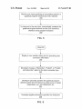
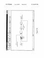
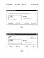
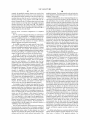
US007624375B2
(12)
United States Patent
(10) Patent N0.:
(45) Date of Patent:
Santori et a].
(54)
AUTOMATICALLY CONFIGURING A
GRAPHICAL USER INTERFACE ELEMENT
TO BIND TO A GRAPHICAL PROGRAM
US 7,624,375 B2
Nov. 24, 2009
5,861,882 A
1/1999 Sprenger et a1.
5,870,746 A *
2/1999
Knutson et al. ........... .. 707/101
(Continued)
(75) Inventors: Michael L. Santori, Austin, TX (US);
FOREIGN PATENT DOCUMENTS
John C. Limroth, Austin, TX (US);
Gregory O. MorroW, Austin, TX (US)
EP
0398646 A2
11/1990
(Continued)
(73) Assignee: National Instruments Corporation,
OTHER PUBLICATIONS
Austin, TX (US)
Notice:
Subject to any disclaimer, the term of this
patent is extended or adjusted under 35
“LabVIEW Simulation Interface Toolkit”, National Instruments
Corp., Oct. 2002, 9 pages. Online retrieved at <http://www.ni.com/
pdf/manuals/370420a.pdf>.*
U.S.C. 154(b) by 830 days.
(Continued)
Primary ExamineriTuan Q Dam
Assistant ExamineriThuy Dao
(74) Attorney, Agent, or FirmiMeyertons Hood Kivlin
Kowert & GoetZel, P.C.; Jeffrey C. Hood; Mark S. Williams
(21) Appl. N0.: 10/460,147
(22)
Filed:
Jun. 12, 2003
(65)
Prior Publication Data
US 2004/0255269 A1
(51)
(57)
Dec. 16, 2004
ABSTRACT
System and methods for con?guring communication
Int. Cl.
G06F 9/44
G06F 3/048
between a graphical program element (GPE) and a graphical
user interface element (GUIE), where the GPE and the GUIE
(2006.01)
(2006.01)
are from different respective graphical program development
environments. In response to receiving user input specifying
(52)
US. Cl. ..................... .. 717/121; 717/105; 715/717;
(58)
Field of Classi?cation Search ..................... .. None
the GPE and GUIE, and a data source/data target association
between them, at least one of the GUIE and the GPE are
See application ?le for complete search history.
programmatically modi?ed to con?gure communication
References Cited
between the GPE and the GUIE. The graphical program is
then executed, where either the GPE performs a function to
715/763
(56)
U.S. PATENT DOCUMENTS
5,163,130
5,475,851
5,481,741
5,553,223
5,801,942
5,825,361
5,828,851
5,838,593
11/1992
12/1995
1/1996
9/1996
9/1998
10/1998
10/1998
11/1998
Hullot
Kodosky et al.
McKaskle et al.
Greenlee et al.
Nixon et al.
Rubin et al.
Nixon et al.
Komatsu et a1.
generate data, provides the data to the GUIE, and the GUIE
displays the received data; or, the GUIE element receives data
from the user, provides the data to the GPE, and the GPE
receives the data and performs a function based on the data.
The user input may be performed via drag-and-drop user
interface technique, line-drawing, command-line, menu, dia
log box, or wizard, etc.
40 Claims, 10 Drawing Sheets
Receive user input specifying an association between a
graphical program element and a GUI element
200
In response to the user input, automatically configure the
graphical program element and the GUI element to
interface during program execution
20_2
US 7,624,375 B2
Page 2
US. PATENT DOCUMENTS
5,966,532 A *
10/1999
McDonald et al. ........ .. 717/105
6,076,952 A
6,078,320 A
6/2000 Gretta et al.
6/2000 Dove et al.
6,102,965 A
8/2000 Dye et al.
6,173,438 B1
6,219,628 B1
1/2001 Kodoskyetal.
4/2001 Kodoskyetal.
6,262,729 B1
7/2001 Marcos et al.
6,370,569 B1*
4/2002
6,374,308 B1
4/2002 Kempfet al.
Austin ...................... .. 709/217
6,496,205 B1
12/2002 White et al.
7,134,085 B2*
7,210,117 B2*
11/2006
4/2007
2001/0020291 A1*
Austin ...................... .. 715/763
Kudukoliet a1. ..
. 717/100
9/2001 Kudukoliet a1.
2001/0034879 A1*
10/2001 Washington et al.
2001/0034881 A1*
10/2001
2001/0045963 A1
2002/0070965 A1
11/2001 Marcos et al.
6/2002 Austin
717/1
. 717/1
Washington ................. .. 717/5
2002/0089538 A1*
7/2002 WenZel et a1. ............. .. 345/763
2002/0101449 A1
8/2002 Friskel
2004/0158812 A1*
8/2004 Dye et al. ................. .. 717/105
FOREIGN PATENT DOCUMENTS
EP
EP
WO
WO
W0
0 803 809
0803809 A2
94/10627
94/15311
W0 03/005337
10/1997
10/1997
5/1994
7/1994
1/2003
OTHER PUBLICATIONS
R.S.D. Wahidanabanu, M.A. Panneer Selvam and K. Udaya Kumar;
“Virtual Instrumentation with Graphical Programming for Enhanced
Detection and Monitoring of Partial Discharges”, Proceedings of the
Electrical Insulation Conference; Sep. 1997; pp. 291-296.
H.J.W. Spoelder, A.H. Ullings and F.C.A. Groen; “Virtual Instrumen
tation: A Survey of Standards and their Interrelation”, Proceedings of
IEEE Instrumentation and Measurement Technology Conference;
May 1997; pp. 676-681; vol. 1.
Luc De Coster; “Grape-II”; Automatic Control and Computer Archi
tectures Department. Katholieke Universiteit Leuven, Belgium, Feb.
22, 1996 [retrieved Oct. 6, 1999] Retrieved from the Internet @
http://www.esat.kuleuven.ac.be/acca; 25 pages.
Sujatha Srinivasan, M. BodruZZaman, A. Shirkhodaie and M.
Malkani; “LabVIEW Program Design for on-line Data Acquisition
and Predictive Maintenance”, Proceedings of the 30th Southeastern
Symposium on System Theory, Mar. 1998; pp. 520-524.
Jose Luis Pino, Michael C. Williamson and Edward A. Lee; “Inter
face Synthesis in Heterogeneous System-Level DSP Design Tools”;
IEEE International Conference on Acoustics, Speech, and Signal
Processing; May 1996; 4 pages.
Shuvra Bhattacharyya, et al.; The Almagest, vol. liPtolemy 0.7
User’s Manual; Regents of the University of California; 1990-1997;
pp. 1-1 through 5-51 (175 pages).
Shuvra Bhattacharyya, et al.; The Almagest, vol. liPtolemy 0.7
User’s Manual; Regents of the University of California; 1990-1997;
pp. 5-52 through 15-7 (176 pages).
Shuvra Bhattacharyya, et al.; The Almagest, vol. liPtolemy 0.7
User’s Manual; Regents of the University of California; 1990-1997;
pp. 15-8 through I-24 (181 pages).
Edward A. Lee; “Design Methodology for DSP”; 1992; 4 pages.
Edward Ashford Lee, Edwin Goei, Jeff Bier and Shuvra Bhat
tacharyya; “A Design Tool for Hardware and Software for Multipro
“LabVIEW Simulation Interface Toolkit”, National Instruments
Corp., Oct. 2003, 37 pages. Online retrieved at <www.ni.com/pdf/
cessor DSP Systems”; May 1989; 4 pages.
“Gabriel 0.7 Overview”, 1990, 5 pages.
manuals/370420b.pdf>.*
Asawaree Kalavade and Edward A. Lee; “Hardware/ Software Co
International search report and written opinion application No. PCT/
Design Using PtolemyiA Case Study”; Proceedings of the First
US2004/019018 mailed Nov. 29, 2005.
International Workshop on Hardware/ Software Codesign; Sep. 1992;
www.mathworks.com “Real-Time Workshop 4 for generating opti
miZed, portable, and customizable code from Simulink models,” Oct.
2000, 6 pages.
The Measurement and Automation Catalog 2001 National Instru
ments Corporation, Copyright 2000, pp. 100 and 101.
“Dynamic System Simulation for MATLAB” Using Simulink, Ver
sion 4, Copyright 1990-2000 by The MathWorks, Inc., pp. 1-2
through 3-28.
LabVIEW User Manual, Chapter 7 “Creating Vis and SubVIs,” 2000,
pp. 7-1 through 7-12 and II-1 through II-2.
18 pages.
Jose Luis Pino; “Software Synthesis for Single-Processor DSP Sys
tems Using Ptolemy”; Master’s Report; May 1993; 48 pages.
Jose Luis Pino, Soonhoi Ha, Edward A. Lee and Joseph T. Buck;
“Software Synthesis for DSP Using Ptolemy”; Journal ofVLSI Sig
nal Processing; 1995; 15 pages.
Jose Luis Pino, Thomas M. Parks and Edward A. Lee; “Mapping
Multiple Independent Synchronous data?ow Graphs onto Hetero ge
neous Multiprocessors”; 28th Annual Asilomer Conference on Sig
nals, Systems, and Computers; Oct. 1994; 6 pages.
“Solutions for Control” Catalog 1999, dSPACE, Copyright 1998
Jose Luis Pino, Thomas M. Parks and Edward A. Lee; “Automatic
dSPACE GmbH; pp. 1-168.
Code Generation for Heterogeneous Multiprocessors”; ICASSP;
Marleen Ade, Rudy Lauwereins, and J .A. Peperstraete; “Hardware
Software Codesign with Grape”; Katholieke Universiteit Leuven,
Belgium, pp. 40-47.
Rudy Lauwereins, Marc Engels, Marleen Ade and J. A. Peperstraete;
“Grape-II: A System-Level Prototyping Environment for DSP Appli
cations”; Feb. 1995; pp. 35-43; Katholieke Universiteit Leuven, Bel
1994; 4 pages.
Asawaree Kalavade and Edward A. Lee; “A Hardware-Software
gium.
X.-P. Ling and H. Amano; “WASMII: a Data Driven Computer on a
Virtual Hardware”; IEEE 1993, pp. 33-42.
A. Takayama, Y. Shibata, K. Iwai, H. MiyaZaki and X. -P. Ling;
“Implementation and Evaluation of the Compiler for WASMII, a
Virtual Hardware System,” 6 pages.
Alan Wenban and Geoffrey Brown; “A Software Development Sys
tem for FPGA-based Data Acquisition Systems”; Proceedings of the
IEEE Symposium on FPGAs for Custom Computing Machines; Apr.
1996; pp. 28-37.
“Lookout Developer’s Manual”; Aug. 1999 Edition; National Instru
ments Corporation; Austin, Texas.
Edward Lee, Edwin Goei, Holly Heine, Wai Ho, Shuvra Bhat
tacharyya, Jeff Bier and Erik Guntvedt; “Gabriel: A Design Environ
Codesign Methodology for DSP Applications”; IEEE Design and
Test ofComputers; Sep. 1993; pp. 16-28.
Ashok Bindra; “Tool Chest continues to Grow”; Electronic Engineer
ing Times; Dec. 15, 1995; 2 pages.
“SPWiMatLAB Co-Simulation InterfaceiIntegrates Matlab a1 go
rithms into SPW designs through seamless co-simulation and ?le
sharing”; Product Data Sheet; 1996; 2 pages.
“6. The Alta Group of Cadence Design Systems, Inc. Signal Process
ing Worksystem (SPW)”; 1995; 34 pages; Berkeley Design Technol
ogy Inc.
“Signal Processing WorkSystemiMatLAB Interface User’s
Guide”; Alta Group of Cadence Design Systems, Inc.; 1995; 72
pages.
“Choosing Block-Diagram Tools for DSP Design”; DSP & Multi
media Technology; Apr. 1995; 7 pages; retrieved from the Internet:
http://www.bdti.com/articles/infoidspmt95blockdiagram.htm.
Speech, and Signal Processing; Nov. 1989; pp. 1751-1762; vol. 37,
“Xanalog Specializing in Workstations for Continuous Dynamic
Simulation”; Presentation; 1987; 24 pages.
“Real-Time User Guide”; 1994; 28 pages.; Xanalog Corporation.
“Xanalog/ RT Real Time Analog and Digital I/O”; Oct. 1990; 4 pages;
No. 11.
Xanalog Corporation.
ment for Programmable DSPs”; IEEE Transactions on Acoustics,
US 7,624,375 B2
Page 3
“The dSpace Real-Time Interface to Simulink for PC”; 1995; 118
Miriam Leeser, Richard Chapman, Mark Aagaard, Mark Linderman
and Stephan Meier; “High Level Synthesis and Generating FPGAs
pages; dSpace.
“Guide to Rapid Prototyping with Simulink, Real-Time Workshop
with the BEDROC System”; Journal of VLSI Signal Processing;
and dSPACE”; 1995; 16 pages; The Math Works.
Kevin J. Gorman and Kouro sh J. Rahnamai; “Real-Time Data Acqui
Christian Boulay, Michel Lafortune, and Robert Guardo; “A High
sition and Controls Using MatLAB”; Proceedings of the Computers
in Engineering Conference and the Engineering Database Sympo
sium; 1995; 4 pages.
Real-Time Workshop, for Use with Simulink, User’s Guide, May
1994, pp. 1-1 through 6-6 (115 pages).
Real-Time Workshop, for Use with Simulink, User’s Guide, May
1994, pp. 6-7 through Index-6 (115 pages).
Joseph T. Buck and Edward A. Lee; “Scheduling Dynamic Data?ow
Graphs with Bounded Memory Using the Token Flow Model”; Insti
tute of Electrical and Electronics Engineers; Apr. 1993; 4 pages.
“Statemate/C” Product Overview; 1995; 4 pages; i-Logix.
“i-Logix Signs Reseller Agreement for Virtual Prototypes, Inc.’s
VAPS Product Line”; Press Release; Feb. 11, 1997; 2 pages.
1993; pp. 191-214.
Throughput Controller for a 256-channel Cardiac Potential Mapping
System”; Canadian Conference on Electrical and Computer Engi
neering; Sep. 1995; pp. 539-542; vol. 1.
Patrick Lysaght and Jon Stockwood; “A Simulation Tool for Dynami
cally Recon?gurable Field Programmable Gate Arrays”; IEEE
Transactions on Very Large Scale Integration (VLSI) Systems; Sep.
1996; pp. 381-390; vol. 4, No. 3.
Michael Petronino, Ray Bambha, James Carswell and Wayne
Burleson; “An FPGA-based data acquisition system for a 95 GHZ
W-band radar”; IEEE International Conference on Acoustics,
Speech, and Signal Processing; Apr. 1997; pp. 4105-4108.
Rudy Lauwereins, Marc Engles and J. A. Peperstraete; “Grape-II: A
System-Level Prototyping Environment for DSP Applications”; Feb.
“i-Logix Introduces Rhapsody, Obj ect-Oriented analysis, Design and
1995; Katholieke Universiteit; Leuven, Belgium.
Implementation Tool”; Press Release; Feb. 10, 1997; 2 pages.
“i-Logix and Integrated Systems Link Statemate Magnum and
Matrix AutoCode”; Press Release; Jan. 3, 1997; 2 pages.
“i-Logix and Wind River unveil Industry’s First Rapid Prototyping
“VisSim/TI C2000 Rapid Prototyper Version 4.5”; 2000; 158 pages;
Third edition; Visual Solutions, Inc.
“VisSim/C-Code 4.0 Automatic C Code Generation Software”; 1
page; Visual Solutions, Inc.
Solution for Testing Embedded Systems at ESC West in San Jose”;
Arun Mulpur; “VisSim/CommDSP Rapid Prototyping Software:
Sep. 17, 1996, 3 pages.
“Express-Statemate Product Family”; 1995; 6 pages; i-Logix, Inc.
“Statemate Technical Overview-Systems Design Automation For
Reactive Systems”; 1996; 14 pages; i-Logix, Inc.
“Statemate Magnum Technical Overview-Systems Design Auto
mation for Complex Systems”; 1996; 18 pages; i-Logix, Inc.
“Xanalog’s CAE System: The Fastest AT Alive”; Mass High Tech;
Aug. 1986; vol. 4, No. 22; 1 page.
“Xanalog Corporation Sales Manual”; Jan. 1987; 8 pages; Xanalog
Communication System to TI DSPs”; 20 pages;Visual Solutions, Inc.
Professional VisSim 4.0 Dynamic Modeling and Simulation Soft
Corporation; Woburn, MA.
ware; 3 pages; Visual Solutions, Inc.
Arun Mulpur; “VisSim/CommDSP Rapid Prototyping Software:
Communication System to TI DSPs”; 20 pages;Visual Solutions, Inc.
Inc.
“VisSim Embedded Controls Developer A Smarter, Faster Way for
Embedded Control Design”; 2 pages; Visual Solutions, Inc.
Edward A. Lee; “Overview ofthe Ptolemy Project”; Feb. 1, 1999; 14
“Available XA-1000 Literature and Its Use”; Jan. 1987; 2 pages.
pages; Department of Electrical Engineering and Computer Science,
University of California; Berkeley, CA.
“Industry News”; Simulation; vol. 47, No. 1, Jul. 1986, 3 pages.
“XA-1000 Programming ICONS”; 1986; 15 pages; Xanalog.
“XA-1000 Programming Examples”; technical data; 6 pages;
Jon Davis, II, et al.; “-Ptolemy II- Heterogeneous Concurrent Mod
eling and Design in JAV ”; Feb. 12,1999; 124 pages; Department of
Electrical Engineering and Computer Science, University of Califor
Xanalog.
nia; Berkeley, CA.
Real-Time Workshop Getting Started; Jul. 2002; 96 pages; Version 5;
The MathWorks, Inc.; Natick, MA.
“Quick quali?cation and pitching of the XA-1000”; Nov. 1986; 4
pages; Xanalog Corporation.
“MultiProx for SPW-Graphical multiprocessor environment for
DSP algorithm development and implementation”; Product Data
Sheet; Aug. 1994; 4 pages; The Alta Group of Cadence Design
Systems, Inc.
“DSP ProCoder for SPW-Translates SPW signal-?ow block dia
grams into highly optimized source code for ?xed point DSP proces
sors”; Product Data Sheet; Nov. 1994; 4 pages; The Alta Group of
Cadence Design Systems, Inc.
“Code Generation System (CGS)iAutomatic C Code generator for
SPW accelerates simulation and enables rapid prototyping of DSP
systems”; Product Data Sheet; 1994; 8 pages; The Alta Group of
Cadence Design Systems, Inc.
“SPW/CGS Porting Kits4Complete software package for interfac
ing the Code Generation System to any processor chip or develop
ment board”; Product Data Sheet; Nov. 1994; 2 pages; The Alta
Group of Cadence Design Systems, Inc.
Jeffrey C. Bier, Edwin E. Goei, Wai H. Ho, Philip D. Lapsley,
Maureen P. O’Reilly, Gilbert C. Sih and EdwardA. Lee; “Gabriel: A
Design Environment for DSP”; IEEE Micro Oct. 1990; pp. 28-45;
vol. 10, No. 5.
Edward A. Lee, Wai-Hung Ho, Edwing E. Goei, Jeffrey C. Bier and
Shuvra Bhattacharyya; “Gabriel: A Design Environment for Pro
grammable DSPs”; IEEE Transactions on Acoustics, Speech, and
Signal Processing; Nov. 1989, pp. 1751-1762; vol. 37, No. 11.
“i-Logix Statemate Magnum Supports PCs”; Press Release; Jan. 31,
1997; 2 pages.
“Xanalog/SC+”; Sep. 1990; 4 pages; Xanalog Corporation; Woburn,
MA.
MD. Edwards and J. Forrest; “Software acceleration using program
mable hardware devices”; IEE Proceedings Computers and Digital
Techniques; Jan. 1996; pp. 55-63; vol. 143, No. 1.
Real-Time Workshop User’s Guide; Jul. 2002; pp. 1-5-59; Version 5;
The MathWorks, Inc.; Natick, MA.
Real-Time Workshop User’s Guide; Jul. 2002; pp. 5-60 through
12-14; Version 5; The MathWorks, Inc.; Natick, MA.
Real-Time Workshop User’s Guide; Jul. 2002; pp. 12-15 through 1-7;
Version 5; the MathWorks, Inc.; Natick, MA.
Real-Time Windows Target User’s Guide-For Use with Real-Time
Workshop; Sep. 2000; 178 pages; Version 2; The MathWorks, Inc.;
Natick, MA.
Simulink ReferenceiModel-Based and System-Based Design; Jul.
2002; pp. 1 through 2-162; Version 5; The MathWorks, Inc.; Natick,
MA.
Simulink ReferenceiModel-Based and System-Based Design; Jul.
2002; pp. 2-163 through 2-354; Version 5; The MathWorks, Inc.;
Natick, MA.
Simulink ReferenceiModel-Based and System-Based Design; Jul.
2002; pp. 2-355 through I-12; Version 5; The MathWorks, Inc.;
Natick, MA.
xPC Target Getting Started; Jul. 2002; 163 pages; Version 2; The
MathWorks, Inc.; Natick, MA.
xPC Target User’s Guide; Jul. 2002; 196 pages; Version 2; The
MathWorks, Inc.; Natick, MA.
xPC Targetbox User’s Guide; Nov. 2002; 136 pages; Version 2; The
MathWorks, Inc.; Natick, MA.
MATRiXx Systembuild User’s Guide, 7.0; Nov. 22, 2000; pp. 1-166;
Wind River Systems, Inc.; Alameda, CA.
MATRiXx Systembuild User’s Guide, 7.0; Nov. 22, 2000; pp. 167
360; Wind River Systems, Inc.; Alameda, CA.
MATRiXx Systembuild User’s Guide, 7.0; Nov. 22, 2000; pp. 361
550; Wind River Systems, Inc.; Alameda, CA.
* cited by examiner
US. Patent
Nov. 24, 2009
Sheet 1 0f 10
US 7,624,375 B2
HCSoymsputemr ‘I02
F1igure
US. Patent
Nov. 24, 2009
WU
Sheet 2 0f 10
ES2Q9O6
om
8ES2Q9O$
Now
US 7,624,375 B2
US. Patent
Nov. 24, 2009
5$5. 3 2 8m32
Sheet 3 0f 10
#3
US 7,624,375 B2
mm?
52 32
.2:2 8
8%?235 wEm?
$2.695E5
omC6?2:6520
US. Patent
Nov. 24, 2009
Sheet 5 0f 10
US 7,624,375 B2
Computer
FIG.4
Network
DAQwBoiatrhd
Proces r
14
1
Stimuls
US. Patent
Nov. 24, 2009
Sheet 6 0f 10
US 7,624,375 B2
Receive user input specifying an association between a
graphical program element and a GUI element
200
V
In response to the user input, automatically configure the
graphical program element and the GUI element to
interface during program execution
20_2
FIG. 5
I Step 200 l
Display a user interface dialog box for specifying data
connection information
E
V
Developer chooses a "Subscribe", "Publish", or "Publish
and Subscribe" option for the data connection type
252
I
Developer optionally specifies the graphical program
element and/or the GUI element as data source or target
respectively, e.g., via DataSocket, etc.
335
I
Developer applies information specified via dialog box
256
FIG. 6
US. Patent
Nov. 24, 2009
Sheet 8 0f 10
US 7,624,375 B2
wuEmwcnm
w-IUI
+521E. 25:.
72.?
2E39i
“min60H
g03:52 ;
2:95 3.53
2: 5
hum w
US. Patent
Nov. 24, 2009
Sheet 9 0f 10
US 7,624,375 B2
DataSocket Connection
Connect To:
lserverl
F
g
El
1
1M‘ ,5 a W
-,- Connection Type
We.”
M ,.
C.“ Wt... -...
H...
w
r
7 f7
7.
WWW.“ . M. .MMM-
5Ul35Ull3'B
Attach
Browse...
I
,- .
Only enabled connections publish andi‘or
(‘-2. Publish and Subscribe
5
m. M:
.
Remove
subscribe datawhen 'i-‘I runs.
l
l
Cancel
lijbataSocket Connection
Mesh"
1
‘Co
Connect To:
mm"
lFf'lVer
li
i
MMM
. Connection
, Subscribe
. Type
-. . . .
1
Publish and Subscribe
Attach
W
W w
Remove 1
FIG. 8B
i
l
Browse...
i?iEnabled
subscribe
Only enabled
dataconnections
when 'iI'I runs.
publish andi'or
i
-C.
1
1.
US. Patent
Nov. 24, 2009
Sheet 10 0f 10
¢ Throttle
' ? Crank spa d
1
F44
m Angle 6F attack
a: Pilot G-Fsrce
,
Ehgine Contrclller
,1; Engine Speed
‘1
i Waveihrm Chant
FIG. 9
US 7,624,375 B2
US 7,624,375 B2
1
2
AUTOMATICALLY CONFIGURING A
GRAPHICAL USER INTERFACE ELEMENT
TO BIND TO A GRAPHICAL PROGRAM
element, Wherein the individual WindoWs may optionally be
tiled together. When the controls and indicators are created in
the front panel, corresponding icons or terminals may be
automatically created in the block diagram by the block dia
gram editor. Alternatively, the user can place terminal icons in
the block diagram Which may cause the display of corre
FIELD OF THE INVENTION
sponding front panel objects in the front panel, either at edit
The present invention relates to the ?eld of graphical pro
gramming, and more particularly to a system and method for
creating an association betWeen a graphical user interface
element and a graphical program, e.g., a block diagram,
Wherein the GUI element can provide data to and/or receive
time or later at run time. As another example, the user inter
face objects or front panel objects may be comprised in or
embedded in the graphical program or block diagram.
Thus, graphical programming has become a poWerful tool
available to programmers. Graphical programming environ
data from the graphical program.
DESCRIPTION OF THE RELATED ART
ments such as the National Instruments LabVIEW product
have become very popular. Tools such as LabVIEW have
Traditionally, high level text-based programming lan
guages have beenused by programmers in Writing application
programs. Many different high level programming languages
greatly increased the productivity of programmers, and
increasing numbers of programmers are using graphical pro
gramming environments to develop their softWare applica
tions. In particular, graphical programming tools are being
exist, including BASIC, C, C++, Java, FORTRAN, Pascal,
COBOL, ADA, APL, etc. Programs Written in these high level
languages are translated to the machine language level by
used for test and measurement, data acquisition, process con
20
data acquisition (SCADA) applications, product design,
translators knoWn as compilers or interpreters. The high level
programming languages in this level, as Well as the assembly
modeling, simulation, and machine vision applications,
among others.
language level, are referred to herein as text-based program
ming environments.
Increasingly, computers are required to be used and pro
grammed by those Who are not highly trained in computer
programming techniques. When traditional text-based pro
gramming environments are used, the user’s programming
skills and ability to interact With the computer system often
become a limiting factor in the achievement of optimal utili
Zation of the computer system.
More recently, a number of graphical program develop
ment environments have been developed Which enable users
to create graphical programs, also referred to as block dia
grams. A graphical program may be de?ned as a program
Which includes graphical code, Wherein the graphical code
comprises a plurality of interconnected nodes Which visually
indicate the functionality of the graphical program. Exem
plary graphical program development environments include
As noted above, a number of graphical program develop
25
ment environments have been developed Which enable users
to create graphical programs. Certain graphical program
30
development environments have different capabilities.
In addition, certain graphical program development envi
ronments have varying types of functionality. For example,
the LabVIEW graphical program development environment
includes a rich graphical user interface capability Which
enables users to create custom user interfaces or front panels
for a graphical program. Other graphical program develop
ment environments may lack a mature graphical user inter
35
face capability. Therefore, it Would be desirable to alloW users
to utiliZe functionality from different graphical program
development environments. More speci?cally, it Would be
desirable to alloW users to utiliZe the graphical user interface
elements from a ?rst graphical program development envi
40
LabVIEW from National Instruments, Simulink from The
MathWorks, VEE from Agilent, Ptolemy, and numerous oth
ers. Graphical programs may be created for virtual instrumen
ronment With graphical programs or block diagrams of a
second graphical program development environment.
In many applications, data received from a data source or
tation systems, industrial automation systems, modeling pro
cesses, and simulation, as Well as for any type of general
trol, man machine interface (MMI), supervisory control and
45
programming.
provided to a data target may be associated With a graphical
user interface (GUI) element. Graphical user interfaces
(GUI s) enable users to interact With computer programs in an
intuitive manner, utiliZing various types of GUI elements.
Different graphical programming environments may enable
During creation of a graphical program, the user may select
various function nodes or icons that accomplish his desired
the function nodes may be connected in one or more of a data 50
developers to include any of various types of GUI elements in
a graphical program’ s graphical user interface or front panel.
For example, GUI elements that may be used in instrumen
How, control How, and/or execution ?oW format. Thus the
tation or measurement applications may include a knob GUI
user may create or assemble a graphical program, referred to
element for adjusting a parameter, e.g., the frequency of a
simulated signal, a chart GUI element for displaying a chart,
result and connect the function nodes together. For example,
as a block diagram, graphically representing the desired pro
cess or system. The assembled graphical program may then
be compiled or interpreted to produce machine language that
e.g., of a poWer spectrum, a thermometer, an LED, a meter, a
55
accomplishes the desired method or process as shoWn in the
block diagram.
A user may also typically create a graphical user interface
(GUI) or front panel for a graphical program. The graphical
user interface or front panel may include various user inter
face elements or front panel objects, such as controls or indi
60
Waveform chart, a tank, etc. Other types of GUI elements that
may be included in a graphical user interface or front panel
include text boxes, check boxes, etc.
GUI elements may be con?gured to indicate data to the
user, e.g., by displaying the data on a display screen. GUI
elements may also be con?gured to provide user input to a
graphical program. For example, When the value of a fre
cators, that represent or display the respective input, output,
quency knob on a user interface panel changes, e.g., due to a
and/ or parameters that Will be used by the graphical program,
and may include other icons Which represent devices being
controlled. The front panel may be comprised in a single
user interactively turning the knob, the graphical program
may detect this change in value, e.g., by intercepting an event
triggered When the value changes, and may respond by
changing the signal that is generated in accordance With the
WindoW of user interface elements, or may comprise a plu
rality of individual WindoWs each having a user interface
65
neW frequency value.
US 7,624,375 B2
3
4
As described above, in many cases, it may be desirable for
data indicated by a GUI element to originate from a data
gram (or graphical program element). In response to receiv
ing user input (e.g., input received from a developer of the
graphical program) creating the association betWeen the GUI
element and the graphical program element, the graphical
source outside of the graphical program, such as a ?le, server,
or other data source. Also, in many cases, it may be desirable
for data associated With a GUI element to be provided to a
program element and/or the GUI element may be automati
cally, i.e., programmatically, con?gured to communicate data
and/or interoperate during program execution. Thus, When
data target outside of the graphical program. For example, a
graphical program to control a system located in a remote
laboratory may have a graphical user interface panel includ
ing various GUI elements such as knobs, buttons, etc. When
a user changes the values associated With the GUI elements,
it may be desirable for the graphical program to send the
the graphical program executes, the GUI element may oper
ate to provide data to and/or receive data from the graphical
program element.
In creating an association betWeen a graphical program
element of the graphical program created in the second
graphical program development environment and a GUI ele
ment from the ?rst graphical program development environ
values to a program running on a computer system in the
remote laboratory Which is operable to send control signals to
the system, based on the received GUI element values.
Therefore, it Would also be desirable to provide a system
ment, the user may begin by selecting either the graphical
and method to simplify data exchange for a graphical pro
program element or the GUI element ?rst.
In one embodiment, the user selects a GUI element from
gram, Wherein the data is associated With a GUI element. For
example, it Would be desirable to provide a method for easily
the ?rst graphical program development environment, e.g.,
enabling a GUI element to subscribe to data from a data
source or publish data to a data target, Wherein the data source
by right clicking on the GUI element. The user may then
select a graphical program element in the graphical program
or data target may be another graphical program.
In some prior art systems, in con?guring a GUI element of
a graphical program, a developer typically ?rst includes the
GUI element in the graphical program’s user interface and
then con?gures the GUI element to interface With a data
source or data target. According to this methodology, the
developer is required to ?rst select an appropriate GUI ele
20
(created in the second graphical program development envi
ronment) With Which to associate the GUI element. Selection
of the graphical program element may involve the user select
ing the graphical program element in the graphical program
25
When the user selects the GUI element and selects an asso
ciation option, the graphical program may be automatically
displayed, and the user may then select the graphical program
ment for the data source or data target, Which, to a certain
extent, places the focus of the program development process
on the GUI element itself. To enable a more natural develop
ment process, it Would be desirable to provide a method that
30
that data source or target Would be automatically included in
35
For example, When the user selects the GUI element and
selects an association option, the graphical program may be
automatically displayed, and the user may then drag and drop
the GUI element proximate to (or onto) the graphical program
subscribe to data from or publish data to the data source or
data target, respectively.
element in the graphical program to create the association (or
vice versa, i.e., the user could drag and drop the graphical
As described above, the task of con?guring a program to
exchange data With a data source or target can be dif?cult and
time-consuming, and some users may not possess the neces
element in the graphical program. Alternatively, selection of
the graphical program element may involve the user graphi
cally associating the GUI element With the graphical program
element (e.g., by dragging and dropping one or both of the
elements, draWing a “Wire” betWeen the tWo elements, etc.).
alloWs the developer to specify the data source or data target
of interest, and in response, a GUI element appropriate for
the program’s user interface and automatically con?gured to
using a pointing device to create the association. For example,
40
program element onto the GUI element to create the as socia
sary knowledge required, especially those users Who are not
tion).
highly trained in programming techniques. Thus, it Would be
out requiring the user to specify or Write any source code. For
example, it may be desirable to provide one or more user 45
interface dialog boxes or WindoWs With Which the user can
The above method may also operate in reverse, e.g., by the
user ?rst selecting the graphical program element and then
associating the graphical program element With a GUI ele
ment. In various embodiments, various other techniques may
be used to select the respective elements and specify the
interact in order to con?gure the graphical program to
exchange data With data sources and/or data targets.
association. For example, in one embodiment, a Wizard may
be provided that leads the user (e.g., via a series of dialogs or
highly bene?cial to enable the user to perform this task With
SUMMARY OF THE INVENTION
50
One embodiment of the present invention comprises a sys
right-clicking on an element, selecting a menu item, e. g.,
from a pop-up menu, and so forth. In another embodiment,
tem and method for enabling a user to associate a graphical
user interface element of a ?rst graphical program develop
ment environment With a graphical program created in a
one or more dialogs may be presented (e.g., invoked by the
55
second graphical program development environment (a sec
ond graphical program). Embodiments of the present inven
tion may be used to enable a user to con?gure communication
betWeen a user interface of a ?rst graphical program devel
opment environment and a graphical program created in a
elements, or in another embodiment, may display the avail
able GUI and/or graphical program elements for selection by
60
the user. The display may take any of a variety of forms. For
example, in one embodiment, a tree vieW (e. g., a tree control
displaying a tree hierarchy) of the available GUI and/or
graphical program elements may be displayed to the user, as
65
beloW. In another embodiment, the user may invoke a cyclic
In one embodiment, the user associates a GUI element
from the ?rst graphical program development environment
second graphical program development environment. This
may cause the GUI element to “bind” to the graphical pro
user) to facilitate selecting and associating the GUI element
and the graphical program element. The dialog(s) may alloW
the user to broWse available GUI and/or graphical program
second graphical program development environment.
With a graphical program (e.g., With a graphical program
element or node of the graphical program) created in the
screens) through the selection and association process. The
WiZard (or any other selection mechanisms described herein)
may be invoked in a variety ofWays, such as, for example, by
simple example of Which is illustrated in FIG. 9, described
display, e.g., by right-clicking on the graphical program ele
ment, Whereby the user may cycle through the selectable GUI
US 7,624,375 B2
5
6
elements until the desired control or indicator is displayed
(and then selected). Of course, the converse is also contem
plated, Where the user invokes the display from the GUI
embodiments, the graphical program element and the GUI
element may reside on the same computer system or may be
located on different computer systems coupled over a net
element, and cycles through the graphical program elements.
Work.
In other embodiments, the elements may be displayed in lists,
Thus, receiving user input associating the GUI element
palettes, menus (e.g., popup menus), or any other form as
desired.
With a graphical program element in the graphical program
For example, many graphical programming environments
may include receiving user input specifying the graphical
include a user interface editor or WindoW for designing a
program element as a data source, and receiving user input
specifying the GUI element as a data target. In this embodi
graphical user interface. The developer may interact With the
user interface editor WindoW to specify the graphical program
ment, programmatically con?guring a communication link
betWeen the graphical program element and the GUI element
element. For example, the developer may drag and drop the
may include programmatically con?guring the GUI element
to receive data from the graphical program element, and/or
pro grammatically con?guring the graphical program element
graphical program element icon, such as the node icon, onto
the GUI element, or the developer may paste in graphical
program element information, e.g., from the clipboard. The
developer may also invoke a user interface dialog for speci
fying the graphical program element, as described above. For
example, the developer may right-click on a GUI element to
display a popup menu for invoking the user interface dialog.
In other embodiments, a palette displaying available selec
tions may be presented to the user, e.g., a palette of graphical
program elements and/or GUI elements. For example, in one
embodiment, the user may invoke presentation of the palette
by right-clicking on a ?rst element, e. g., a graphical program
element or GUI element, and a “smart palette” may be pre
sented to the user displaying only those elements (e.g., GUI
elements or graphical program elements) that are compatible
to send data to the GUI element.
Alternatively, receiving user input associating the GUI ele
ment With a graphical program element in the graphical pro
gram may include receiving user input specifying the graphi
20
ment, programmatically con?guring a communication link
betWeen the graphical program element and the GUI element
may include programmatically con?guring the graphical pro
gram element to receive data from the GUI element, and/or
25
such as the tree hierarchy and lists mentioned above, the
30
With the user-selected ?rst element.
As another example, many graphical programming envi
35
receiving data from the speci?ed data source; and 2) publish
ing data to the speci?ed data target.
45
graphical program, e.g., by “dropping” the element onto the
program diagram, a communication link is automatically
established betWeen the GUI element and the graphical pro
gram element. Thus, in various embodiments, one or both of
the GUI element and the graphical program element may be
and the graphical program element representing the desired
association betWeen the tWo elements. For example, draWing
con?gured or pre-con?gured to establish a communication
50
graphical program element, While draWing a line from the
graphical program element to the GUI element may indicate
that data is to How from the graphical program element to the
GUI element. Alternatively, once a line is draWn, options may
be presented Whereby the user may specify a direction for the
line indicating the direction of data How betWeen the tWo
elements. In one embodiment, both directions may be speci
?ed, indicating that data is to How in both directions. For
program to programmatically perform at least one of: 1)
40
invoking the dialog.
a line from the GUI element to the graphical program element
may indicate that data is to How from the GUI element to the
In one embodiment, programmatically con?guring
includes automatically creating and storing a data structure
In yet another embodiment, an association betWeen the
GUI element and the graphical program element may be
established prior to creation of the graphical program. For
example, in one embodiment, the graphical program element
may be pre-con?gured to be associated With the GUI element
such that When the graphical program element is added to the
graphical program element to display a popup menu for
In yet another embodiment, a user may use a pointing
device to draW a line, e. g., a “Wire”, betWeen the GUI element
a data source and a data target.
comprising source/target information, Where the source/tar
get information is useable during execution of the graphical
ronments include a graphical program editor (or block dia
gram editor) or WindoW for designing a graphical program.
The developer may interact With the graphical program editor
WindoW to specify the GUI element. For example, the devel
oper may drag and drop the GUI element icon onto the graphi
cal program element, or the developer may paste in graphical
program element information, e.g., from the clipboard. The
developer may also invoke a dialog from the graphical pro
gram editor for specifying the GUI element, as described
above. For example, the developer may right-click on a
programmatically con?guring the GUI element to send data
to the graphical program element.
As indicated above, in one embodiment the GUI element
and/or the graphical program element may be treated as both
With the ?rst element. Similarly, in other display approaches,
displays may only include those elements that are compatible
cal program element as a data target, and receiving user input
specifying the GUI element as a data source. In this embodi
link such that upon execution of the graphical program the
GUI element and the graphical program element may be
operable to communicate.
Once the graphical program and/or the GUI element has
been automatically con?gured to interface as a data source or
55
target as described above, the graphical program may be
executed. During program execution, the graphical program,
e.g., the graphical program element and the GUI element are
operable to automatically, i.e., programmatically, communi
graphical program element. The graphical program element
cate data in an appropriate format. It should be noted that in
different embodiments, the communication of data from the
data source to the data target may be implemented as a “push”
or a “pull” operation, Where a push operation Would involve
the data source actively sending data to the data target, and a
may then implement the neW status or value, i.e., may perform
pull operation Would involve the data target retrieving data
example, a GUI element may display a status or value asso
ciated With the graphical program element, i.e., may function
as an indicator, and may also receive user input specifying a
neW status or value Which may be communicated to the
60
a function or action Which sets the status or value to the 65 from the data source. In another embodiment, the data source
communicated value. In other Words, the GUI element may
may send data to a separate layer or component, e. g., a
also function as a control. It should be noted that in different
memory location or data structure, and the data target may
US 7,624,375 B2
7
8
retrieve the data from the component, thus using both push
and pull operations to communicate the data.
If the developer con?gured the graphical program element
viding the data to the graphical program element, and the
graphical program element receiving the data and performing
to subscribe to data from the GUI element, then during pro
gram execution, the GUI element may receive user input data
and/ or may generate data. This data may then be provided to
In other embodiments, multiple GUI elements and/or
graphical program elements may be linked in one-to-many
associations. For example, in one embodiment, after a linkage
the graphical program element (i.e., block diagram element)
has been established betWeen the GUI element (from a ?rst
a function based on the data.
With Which the developer associated the GUI element. The
data may then be processed according to the functionality of
graphical program development environment) and the
graphical program element in the graphical program (from a
second graphical program development environment), a sec
ond graphical program may be created in the ?rst graphical
program development environment. Second user input may
be received associating the graphical user interface element
this graphical program element. If the developer con?gured
the graphical program element to publish data to the GUI,
then during program execution, the graphical program ele
ment may operate to generate data and provide the data to the
GUI element, such as for display.
As noted above, in one embodiment, the graphical program
With a second graphical program element in the second
graphical program. At least one of the graphical user interface
element and the second graphical program element may then
element and the GUI element may utiliZe a separate layer or
component for interfacing With each other. One embodiment
of such a layer, referred to as “DataSocket”, is described. In
general, DataSocket provides a single, uni?ed, end-user
application programming interface (API) for connecting to
20
be programmatically modi?ed to con?gure communication
betWeen the second graphical program element and the
graphical user interface element, Where, after said con?gur
ing, the graphical user interface element and the second
data from a number of sources, such as local ?les, ?les on FTP
or Web servers, and data items on OPC Servers. For example,
graphical program element are operable to communicate dur
ing execution of the second graphical program. Thus, in one
a DataSocket application may specify the data location by
using a Universal Resource Locator (URL). As another
example, a DataSocket Transfer Protocol (DSTP) may con
nect a DataSocket application to live data by specifying a
embodiment, the ?rst graphical program and the second
graphical program may be executed concurrently, Where dur
ing the execution the graphical user interface element and the
?rst graphical program element are operable to communicate,
connection to a DataSocket Server. In various embodiments
and the graphical user interface element and the second
graphical program element are also operable to communi
cate. In another embodiment, the second graphical program
may be created (and may reside) in a third graphical program
of the present invention, DataSocket may be used to specify
and implement a communication path betWeen the graphical
program element and the GUI element.
DataSocket may transfer data in a self-describing format
that can represent data in a substantially unlimited number of
30
development environment.
In a further embodiment, one or more second graphical
programs may be created in one or more respective third
formats, including strings, scalars, Booleans, and Waveforms.
The DataSocket read and Write operations transparently con
vert data to and from the underlying byte streams, eliminating
the need to Write complicated parsing code. DataSocket may
thus use the DataSocket Transport Protocol, referred to
above, to send data to and receive data from the graphical
program element and/or the GUI element. Although DataS
ocket is described above for specifying and implementing a
35
graphical program development environments, and second
user input may be received associating the graphical user
interface element With each of a respective one or more
graphical program elements in the one or more second
graphical programs. At least one of the graphical user inter
40
face element and the one or more second graphical program
communication path betWeen the graphical program element
elements may be programmatically modi?ed to con?gure
communication betWeen the graphical program element and
and the GUI element, it should be noted that other technolo
the one or more second graphical user interface elements,
gies are also contemplated, including, for example, object
technologies such as DCOM (Distributed Component Object
Model), ActiveX, CORBA (Common Object Request Broker
Where, after said con?guring, the graphical user interface
45
element and the one or more graphical program elements are
operable to communicate during execution of the one or more
Architecture), custom TCP/IP protocol, and callback func
tions, among others.
In one embodiment, the ?rst graphical program element
second graphical programs.
In an alternate embodiment, after the linkage has been
cal user interface element and the ?rst graphical program
establishedbetWeen the GUI element (from the ?rst graphical
program development environment) and the graphical pro
gram element in the graphical program (from the second
graphical program development environment), a second
element are operable to communicate over the netWork dur
graphical user interface element may be selected from the
and the GUI element may reside and execute on respective
50
computer systems coupled over a netWork, Where the graphi
ing execution of the graphical program. Thus, the ?rst graphi
cal program development environment and the second
graphical program development environment may each
reside on the respective computer systems.
Thus, if the graphical program element is speci?ed as a
55
user interface element With the ?rst graphical program ele
ment in the graphical program. One or more of the second
graphical user interface element and the ?rst graphical pro
gram element may be programmatically modi?ed to con?g
data source and the GUI element is speci?ed as a data target,
executing the graphical program may include the graphical
60
program element performing a function to generate data, the
graphical program element providing the data to the GUI
element, and the GUI element displaying the received data.
Alternatively, if the GUI element is speci?ed as a data source
and the graphical program element is speci?ed as a data
second graphical program development environment. Second
user input may be received associating the second graphical
65
ure communication betWeen the ?rst graphical program ele
ment and the second graphical user interface element, Where,
after said con?guring, the second graphical user interface
element and the ?rst graphical program element are operable
to communicate during execution of the graphical program.
In another embodiment, the second graphical user interface
target, executing the graphical program may include the GUI
element may be selected from a third graphical program
element receiving data from the user, the GUI element pro
development environment.
US 7,624,375 B2
10
In yet another embodiment, once the linkage has been
establishedbetween the GUI element (from the ?rst graphical
described in detail. It should be understood, however, that the
drawings and detailed description thereto are not intended to
limit the invention to the particular form disclosed, but on the
contrary, the intention is to cover all modi?cations, equiva
lents and alternatives falling within the spirit and scope of the
present invention as de?ned by the appended claims.
program development environment) and the graphical pro
gram element in the graphical program (from the second
graphical program development environment), one or more
second graphical user interface elements created in one or
more respective third graphical program development envi
DETAILED DESCRIPTION OF THE PREFERRED
EMBODIMENTS
ronments may be selected. Second user input may be received
associating each of the respective one or more graphical user
interface elements with the graphical program element. Then,
at least one of the one or more second graphical user interface
Incorporation by Reference
The following patent applications are hereby incorporated
elements and the graphical program element may be pro
grammatically modi?ed to con?gure communication
by reference in their entirety as though fully and completely
between the graphical program element and the one or more
set forth herein:
second graphical user interface elements, where, after said
US. patent Ser. No. 09/185,161 titled “Data Socket System
and Method for Accessing Data Sources Using URLs” ?led
con?guring, the one or more graphical user interface ele
ments and the graphical program element are operable to
on Nov. 3, 1998, whose inventor was Paul Austin.
communicate during execution of the graphical program.
Thus, the present invention comprises various embodi
ments for simplifying or automating the task of con?guring a
?rst graphical program (created in a ?rst graphical program
US. Pat. No. 6,173,438 titled “Embedded Graphical Pro
20
development environment) to exchange data with and/or
interoperate with GUI elements created in a different graphi
cal program development environment, whether they be
ActiveX control-based, conform to another object technol
25
ogy, or reside in a different graphical program development
environment, possibly on a different computer.
Sierer, Kurt Carlson, Stephen Rogers and Chris Mayer, and
US. patent application Ser. No. 09/518,492 titled, “System
and Method for Programmatically Creating a Graphical Pro
30
A better understanding of the present invention can be
chi, and which issued as US. Pat. No. 7,159,183 on Jan. 2,
2007.
ferred embodiment is considered in conjunction with the
following drawings, in which:
35
menting various embodiments of the present invention;
was Paul F. Austin, and which issued as US. Pat. No. 6,763,
395 on Jul. 13,2004.
40
options;
FIG. 5 is a ?owchart diagram illustrating one embodiment
of a method for automatically con?guring communications
45
interface (GUI) element;
50
log box for specifying data connection information, wherein
7, 2006.
55
FIG. liA Computer System
FIG. 1 illustrates a computer system suitable for imple
menting various embodiments of the present invention. The
computer system 102 may store and/or execute a software
FIGS. 8A and 8B illustrate exemplary dialog boxes for
program which performs the method described with refer
60
ence to FIGS. 5-6, described below. In one embodiment, the
computer system 102 may include a display device, such as a
monitor, as well as a chassis and one or more I/O devices,
linkage between a LabVIEW GUI element and a Simulink
graphical program element.
While the invention is susceptible to various modi?cations
and alternative forms, speci?c embodiments thereof are
shown by way of example in the drawings and are herein
US. patent application Ser. No. 09/ 737,639 titled, “System
and Method for Automatically Con?guring Program Data
Exchange,” ?led on Dec. 13, 2000, whose inventor was Paul
Austin, and which issued as US. Pat. No. 7,134,085 on Nov.
FIG. 7A illustrates a GUI element with an exemplary dia
specifying subscription and publishing relationships for a
DataSocket Connection; and
FIG. 9 illustrates an exemplary dialog box for specifying
US. patent application Ser. No. 09/ 737,528 titled, “System
and Method for Automatically Con?guring a Graphical Pro
gram to Publish or Subscribe to Data” ?led on Dec. 13, 2000,
whose inventor is Paul Austin, and which issued as US. Pat.
No. 6,971,065 on Nov. 29, 2005.
specifying the association information;
the user has chosen a “Link to Simulink” option specifying
that the GUI element should be linked to a graphical program
element in a Simulink graphical program;
FIG. 7B illustrates an exemplary Simulink graphical pro
gram;
US. patent application Ser. No. 09/ 737,527 titled, “System
and Method for Con?guring a GUI Element to Publish or
Subscribe to Data,” ?led on Dec. 13, 2000, whose inventors
were Paul F. Austin and Robert Dye, and which issued as US.
Pat. No. 7,287,230 on Oct. 23, 2007.
FIG. 4 illustrates an exemplary data acquisition system;
FIG. 6 is a ?owchart diagram illustrating one embodiment
of a method for receiving user input specifying an association
between a graphical program element and a GUI element,
wherein the developer invokes a user interface dialog box for
US. patent application Ser. No. 09/ 546,047 titled, “System
and Method for Connecting to andViewing Live Data using a
Standard User Agent,” ?led onApr. 10, 2000, whose inventor
FIG. 2 illustrates an exemplary networked computer sys
between a graphical program element and a graphical user
gram,” ?led on Mar. 3, 2000, whose inventors were Ram
Kudukoli, Robert Dye, Melanie Jensen, and Yumiko Kawa
obtained when the following detailed description of the pre
tem;
FIGS. 3A and 3B illustrate representative instrumentation
and process control systems including various I/O interface
Data Sources and Data Targets” ?led onAug. 13, 1999, who se
inventors were Paul F. Austin, David W Fuller, Brian H.
which issued as US. Pat. No. 7,152,116 on Dec. 19, 2006.
BRIEF DESCRIPTION OF THE DRAWINGS
FIG. 1 illustrates a computer system suitable for imple
gramming System”, which was ?led Aug. 18, 1997, whose
inventors were Jeffrey L. Kodosky, Darshan Shah, Samson
DeKey, and Steven W. Rogers.
US. patent application Ser. No. 09/ 374,740 titled, “System
and Method for Automatically Creating URLs for Accessing
65
such as a keyboard and/or mouse. However, the computer
system may take any of various forms, such as a personal
computer, or any type of device which includes a processor
that executes instructions from a memory medium, or which
includes programmable logic that has been con?gured to
US 7,624,375 B2
11
12
perform the methods described in FIGS. 5-6. Exemplary
computer systems include a personal computer, mainframe
execute a server program (or process) with which the graphi
cal program and the GUI element interface in order to
computer, a personal computing device (PDA), television,
exchange data.
embedded device, and other systems. Thus, as used herein,
One embodiment of such a server program, referred to
the term computer system is intended to encompass any of
herein as a “DataSocket server,” may be used to implement
the communication channel between the two elements. In
various devices which include a processor that can execute
instructions from a memory medium and/or may include a
general, DataSocket, developed by National Instruments Cor
poration, provides a single, uni?ed, end-user application pro
programmable logic device that can be con?gured to execute
gramming interface (API) for connecting to data from a num
a method or algorithm, such as that described in FIGS. 5-6.
ber of sources, such as local ?les, ?les on FTP or Web servers,
and data items on OPC Servers. For example, a DataSocket
Thus, the method of the present invention may be imple
mented in any of various types of devices and any of various
Transfer Protocol (DSTP) may connect a DataSocket appli
cation to data by specifying a connection to a DataSocket
Server. In various embodiments of the present invention,
DataSocket may be used to specify and implement a commu
types of applications. Example applications where the
method described herein may be used include instrumenta
tion systems, industrial automation or process control sys
tems, telecommunication systems, machine vision systems,
simulation and modeling, and any other application where it
is desirable to con?gure communications between a graphical
program and a graphical user interface. More speci?c appli
cations wherein the method of the present invention may be
used include test and measurement, control design, control
analysis, dynamic system simulation, as well as analysis
related to image data, measurement data, acoustic data, seis
mic data, ?nancial data, stock data, futures data, business
data, scienti?c data, medical data, insurance data, musical
data, biometric data, and telecommunications signals, among
nication path between the graphical program element and the
GUI element. DataSocket may transfer data in a self-describ
ing format that can represent data in a substantially unlimited
number of formats, including strings, scalars, Booleans, and
20
eliminating the need to write complicated parsing code.
25
30
interface with a server program also executing on the com
35
illustrates an exemplary networked computer system. It is
noted that FIG. 2 is exemplary only and that in various
embodiments the present invention may be used in any type of
40
network.
FIG. 2 illustrates an exemplary system in which a ?rst
computer system 102 is connected through a network 84 to a
system 102, and the server and GUI element may execute on
45
50
from the graphical program element, e.g., by displaying the
55
data in various ways, and/or such that the GUI element
receives user input or generates data which is received by the
graphical program element and processed in accordance with
the graphical program element’s speci?ed functionality.
60
To illustrate one example of a graphical program element
and an associated GUI element, consider a graphical program
element executing on a computer system in a laboratory,
wherein the graphical program element is operable to con
tinuously acquire signal data from a hardware unit under test.
As noted above, in a preferred embodiment, the graphical
uses or displays the data generated by the ?rst computer
system 102. In one embodiment, the graphical program ele
ment and the GUI element may utiliZe a separate layer or
gram element, by automatically con?guring the graphical
program to interface with the GUI element (and/ or con?gur
ing the GUI element to interface with the graphical program
element), such that the GUI element indicates data received
also be any of various types, including the Internet, a LAN
(local area network), or a WAN (wide area network), among
others.
In one embodiment, the ?rst computer system 102 may
execute a graphical program, e.g., a graphical program ele
ment, such as a node or terminal, that generates data, and the
second computer system 90 may execute a GUI element that
the graphical program element. Alternatively, the graphical
program element may be con?gured to subscribe to the GUI
element. As described below, one embodiment of the present
invention enables the program developer to easily associate a
GUI element with a graphical program, e.g., a graphical pro
second computer system 90. The computer systems 102 and
90 can be any of various types, as desired. The network 84 can
program element. For example, the GUI element may execute
on the computer system 90, e.g., as shown in FIG. 2, or may
execute on the same computer system 102. Alternatively, the
graphical program element may execute on the computer
the computer system 90.
Thus, the GUI element may be con?gured to subscribe to
system, including a system with only one computer, as well as
a system with three or more computers coupled over the
puter system 102. In this case, the GUI element may interface
with the server program executing on the computer system
102 in order to receive the data generated by the graphical
graphical program development environments that normally
are unable to communicate or operate cooperatively. FIG. 2
In one embodiment, the server program may execute on a
third computer coupled to the ?rst and second computer sys
tems over the network 84. For example, the computer system
102 may execute the graphical program element which may
ferent graphical program development environments, such
as, for example, National Instruments’ LabVIEW graphical
program development environment and the Simulink graphi
cal program development environment from The Math
Works. In other words, linkages may be established between
graphical program elements and GUI elements from different
DataSocket may thus use the DataSocket Transport Protocol
to send data to and receive data from the graphical program
element and/or the GUI element. For further information
regarding Data Sockets, please see US. patent Ser. No.
09/ 185,161 titled “Data Socket System and Method for
Accessing Data Sources Using URLs” ?led on Nov. 3, 1998,
which was incorporated by reference above.
others.
FIG. 24Computer Systems Connected Via a Network
One embodiment of the present invention enables program
developers to easily associate a graphical program element in
a graphical program with a GUI element for data exchange,
including cases where the graphical program and the GUI
element execute on separate computer systems. Additionally,
in various embodiments, the graphical program element and
the GUI element may be developed and/or comprised in dif
waveforms. The DataSocket read and write operations trans
parently convert data to and from the underlying byte streams,
65
program element and the GUI element may be developed
component for interfacing with each other. For example, in
and/or comprised in different graphical program develop
one embodiment, one of the computer systems may also
ment environments, where the graphical program elements
US 7,624,375 B2
13
14
and GUI elements normally are unable to communicate or
FIGS. 3A and 3BiInstrumentation and Industrial Automa
operate in conjunction With one another.
tion Systems
FIGS. 3A and 3B illustrate an exemplary computer 102
having various types of instruments or hardWare devices con
In one case, the GUI element may comprise a chart GUI
element operable to display the signal data as a tWo-dimen
sional Waveform. In this case, the developer of the graphical
nected. In various embodiments, the computer 102 may be
any of the computers 102 or 90 discussed above. For example,
program element may easily con?gure the graphical program
element to publish the signal data to the GUI element by
simply associating the graphical program element With the
a graphical program element may execute on the computer
102 and may Write data acquired from a connected hardWare
device to a data target. It is noted that FIGS. 3A and 3B are
chart GUI element, according to one embodiment of the
present invention. For example, as described beloW, the
developer may simply invoke a user interface dialog box and
specify the chart GUI element as the data target. In response,
exemplary only, and in alternative embodiments, graphical
program elements and/or GUI elements such as described
herein may execute on any of various types of systems and
the graphical program element may be automatically, i.e.,
programmatically, con?gured to provide the signal data to the
chart GUI element during execution of the graphical program
element. Thus, the developer of the graphical program ele
may be used in any of various applications.
FIG. 3A illustrates an instrumentation control system 100.
The system 100 comprises a host computer 102 Which con
nects to one or more instruments. The host computer 102
comprises a CPU, a display screen, memory, and one or more
input devices such as a mouse or keyboard as shoWn. The
computer 102 connects through the one or more instruments
ment may not need to specify or Write any source code to
accomplish the publication of the signal data to the GUI
element.
In one embodiment, a user may execute the GUI element in 20 to analyZe, measure, or control a unit under test (UUT) or
a remote computer system outside of the laboratory, in order
to remotely monitor the hardWare unit under test.
process 150.
The developer of the GUI element may easily con?gure the
GUI element to subscribe to and display the signal data by
ment 112 and associated GPIB interface card 122, a data
simply specifying the desired graphical program element,
The one or more instruments may include a GPIB instru
acquisition board 114 and associated signal conditioning cir
25
cuitry 124, a VXI instrument 116, a PXI instrument 118, a
according to one embodiment of the present invention. For
video device 132 and associated image acquisition card 134,
example, the developer may provide a reference to the graphi
cal program element, e.g., by typing an identi?er or pasting
a motion control device 136 and associated motion control
interface card 138, and/or one or more computer based instru
the identi?er into a user interface editor WindoW or block
diagram editor WindoW (or by dragging/dropping, etc.). In
30
response, the graphical program development environment
may be operable to determine that a chart GUI element is an
appropriate GUI element to display data received from the
speci?ed graphical program element, as describedbeloW. The
graphical program development environment may then auto
matically associate the chart GUI element With the graphical
program element, thereby including the chart GUI element in
the program’s graphical user interface. In another embodi
ment, the developer may ?rst include the chart GUI element
in the program’s GUI manually and may then specify the
graphical program element for the GUI element.
The GUI element Which is included (either automatically
or manually) in the program’s GUI may then be automati
ment cards 142, among other types of devices.
The GPIB instrument 112 is coupled to the computer 102
via the GPIB interface card 122 provided by the computer
102. In a similar manner, the video device 132 is coupled to
the computer 102 via the image acquisition card 134, and the
35
motion control device 136 is coupled to the computer 102
through the motion control interface card 138. The data
acquisition board 114 is coupled to the computer 102, and
may interface through signal conditioning circuitry 124 to the
UUT. The signal conditioning circuitry 124 preferably com
prises an SCXI (Signal Conditioning eXtensions for Instru
40
mentation) chassis comprising one or more SCXI modules
126.
The GPIB card 122, the image acquisition card 134, the
motion control interface card 138, and the DAQ card 114 are
typically plugged in to an I/O slot in the computer 102, such
cally, i.e., programmatically, con?gured to receive the signal
data from the graphical program element during execution of
the GUI element and display the signal data. Thus, the devel
as a PCI bus slot, a PC Card slot, or an ISA, EISA or Micro
oper of the GUI element may not need to specify or Write any
these cards 122, 134, 138 and 114 are shoWn external to
computer 102 for illustrative purposes.
The VXI chassis or instrument 116 is coupled to the com
puter 102 via a VXI bus, MXI bus, or other serial or parallel
Channel bus slot provided by the computer 102. HoWever,
source code to accomplish the acquisition and display of the
signal data.
It is noted that although the above description relates to the
50
bus provided by the computer 102. The computer 102 pref
case Where the graphical program element is the data source
and the GUI element is the data target, the converse may be
erably includes VXI interface logic, such as a VXI, MXI or
achieved through similar means. For example, the GUI ele
GPIB interface card (not shoWn), Which interfaces to the VXI
ment may be a control element that operates to send or pro
chassis 116. The PXI chassis or instrument is preferably
vide data for the associated graphical program element. The
data may be received by the GUI element from the user, or
may be generated by the GUI element, and then sent by the
GUI element or retrieved by the graphical program element.
The graphical program element may then modify or con?gure
its state, e. g., may modify or con?gure the state of related data
55
computer 102 through a serial port, such as an RS-232 port,
USB (Universal Serial bus) or IEEE 1394 or 1394.2 bus,
provided by the computer 102. In typical instrumentation
60
structures or program code in accordance With the received
data.
As noted above, in some embodiments, each of the GUI
element and the graphical program element may be both a
data source and a data target, Where the tWo elements com
coupled to the computer 102 through the computer’ s PCI bus.
A serial instrument (not shoWn) may also be coupled to the
65
control systems an instrument Will not be present of each
interface type, and in fact many systems may only have one or
more instruments of a single interface type, such as only
GPIB instruments.
The instruments are coupled to the unit under test (UUT) or
process 150, or are coupled to receive ?eld signals, typically
municate data back and forth betWeen them during the execu
generated by transducers. The system 100 may be used in a
tion of the graphical program.
data acquisition and control application, in a test and mea