1
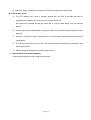
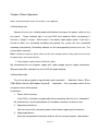
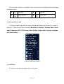
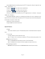
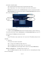
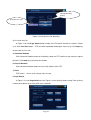
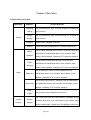
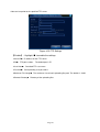
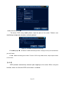
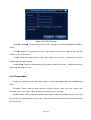
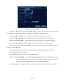
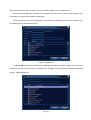
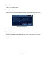
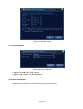
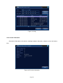
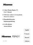
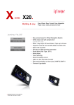
INSTALLATION/OPERATING MANUAL
CAUTION:
Do not place heavy objects on top of the product.
Do not drop any hard objects or allow liquid to penetrate into the unit.
Regularly brush off dust on the circuit board, connectors, fans and DVR case. Turn off the power and
unplug the product before cleaning.
Do not attempt to disassemble or repair the unit or replace parts yourself.
Operating Environment:
Keep and use the product at temperatures between 0 °C ~40 °C. Keep it away from direct sunlight
or heat sources.
Do not install the unit in a humid environment.
Do not expose the product to a smoky or dusty area.
Avoid serious collision. Do not drop the device.
Install the product on a stable and level surface to prevent the device from falling.
Ensure the location planned for DVR installation is well ventilated. Do not block any openings.
Use the product only within the range of rated input/output.
Page 1
Table of Contents
Chapter 1 Introduction ............................................................................................................................................. 4
1.1 Product Overview ......................................................................................................................................... 4
1.2 Main Features................................................................................................................................................ 4
Chapter 2 Unpacking Inspection and Cable Connections ................................................................................. 7
2.1 Unpacking ..................................................................................................................................................... 7
2.2 Rack mount ................................................................................................................................................... 7
2.3 Front Panel .................................................................................................................................................... 8
2.4 Connection Diagram ..................................................................................................................................... 9
2.5 Audio/Video IO Connections ........................................................................................................................ 9
2.5.1 Connect Video Input....................................................................................................................... 9
2.5.2 Selection and Connection of Video Output Devices ............................................................... 10
2.5.3 Audio Signal Input ........................................................................................................................ 10
2.5.4 Audio Output: ................................................................................................................................ 10
Chapter 3 Basic Operation ................................................................................................................................... 12
3.1 Turn Power On ............................................................................................................................................ 12
3.2 Turn Power Off ........................................................................................................................................... 12
3.3 Log in .......................................................................................................................................................... 13
3.4 Preview ....................................................................................................................................................... 13
3.5 Desktop Quick Launch................................................................................................................................ 14
3.5.1 Main Menu ..................................................................................................................................... 14
3.5.2 Video Playback ............................................................................................................................. 15
3.5.3 Recording Control ........................................................................................................................ 19
3.5.4 Alarm Output ................................................................................................................................. 19
3.5.5 PTZ Control ................................................................................................................................ 20
3.5.6 Image Color ................................................................................................................................... 26
3.5.7 Output Adjustment ........................................................................................................................ 26
3.5.8 System Shutdown ........................................................................................................................ 27
3.5.9 Page Switch .................................................................................................................................. 27
Chapter 4 Main Menu ............................................................................................................................................ 28
4.1 Main Menu Navigation ............................................................................................................................... 28
4.2 Video Recording Functions ......................................................................................................................... 30
4.2.1 Recording settings........................................................................................................................ 30
4.2.2 Video Playback ............................................................................................................................. 32
4.2.3 Video Backup ................................................................................................................................ 32
4.3 Alarm .......................................................................................................................................................... 33
4.3.1 Motion Detection........................................................................................................................... 33
4.3.2 Video Masking .............................................................................................................................. 36
4.3.3 Video Loss ..................................................................................................................................... 37
4.3.4 Alarm Input .................................................................................................................................... 37
4.3.5 Alarm Output ................................................................................................................................. 38
4.3.6 Exception Handling ...................................................................................................................... 38
4.4 System Settings ........................................................................................................................................... 39
Page 2
4.4.1 General Settings ........................................................................................................................... 39
4.4.2 Encoding Settings ........................................................................................................................ 40
4.4.3 Network Settings........................................................................................................................ 42
4.4.4 Network Service............................................................................................................................ 43
4.4.5 Output Mode ................................................................................................................................. 49
4.4.6 PTZ Settings ................................................................................................................................. 51
4.4.7 Serial Port Settings ...................................................................................................................... 52
4.4.8 Auto Sequence Settings .............................................................................................................. 52
4.5 Management Tools ...................................................................................................................................... 53
4.5.1 Hard Drive Management ............................................................................................................. 53
4.5.2 User Management ........................................................................................................................ 54
4.5.3 Online User ................................................................................................................................... 57
4.5.4 Output Adjustment ........................................................................................................................ 58
4.5.5 Auto Maintenance......................................................................................................................... 58
4.5.6 Restore Default ............................................................................................................................. 58
4.5.7 System Upgrade ........................................................................................................................... 59
4.5.8 Device Information ....................................................................................................................... 59
4.6 System Information ..................................................................................................................................... 60
4.6.1 Hard Drive Information ................................................................................................................ 60
4.6.2 Stream Statistics ........................................................................................................................... 61
4.6.3 Log .................................................................................................................................................. 61
4.6.4 Version Information ...................................................................................................................... 62
4.7 System Shutdown........................................................................................................................................ 63
Chapter 5 FAQ and Maintenance ........................................................................................................................ 64
5.1 FAQ ............................................................................................................................................................. 64
5.2 Maintenance ................................................................................................................................................ 69
Appendix 1. Mouse Operations ............................................................................................................................ 71
Appendix 2. Hard Drive Capacity Calculation .................................................................................................... 72
Page 3
Chapter 1 Introduction
1.1 Product Overview
This device is an excellent digital surveillance product specially designed for security
monitoring. The system is more stable with embedded LINUX OS, using standard H.264MP
video compression and unique spatial-temporal reasoning to achieve synchronized high
definition and low bit rate audio/video monitoring. With TCP/IP network technologies, it has
ideally suited to remote data transmission and operation control via web applications.
This product can operate not only as a stand alone local unit, through a professional
network video surveillance platform, it can also be connected to other units to form a more
powerful surveillance network system, making full use of its capacity in networking and
remote monitoring.
It is a perfect choice for security applications in industries and sectors such as banking,
telecommunication, electricity, law enforcement, transportation, intelligent community,
manufacturing facilities, warehouses, natural resources and water conservation facilities.
1.2 Main Features
Real-time surveillance
·Analog output interface and VGA connector to connect monitoring device or screen display.
·2 BNC outputs and 1 HD VGA for simultaneous real-time monitoring
·Real-time screen preview with zoom-in feature. You may select any area in the display to enlarge
Data storage
·Hibernate inactive hard drive in hard drive management, helping ventilation and reducing power
consumption to extend the useful life of the hard drives
·Data storage using tamper-proof proprietary file format to ensure data security
Compression method
·Live data compression of A/V signals from each channel by independent hardware to maintain the
stable synchronization of sound and image
Backup feature
Page 4
·Backup through SATA interface and USB interface(to devices such as flash drive or removable hard
disk)
·Live disk burning, backup burning
·Local archiving by downloading files on hard drives via network to client’s PC
Video playback
·Each channel records all-live video independently while simultaneously providing retrieval, playback,
network monitoring, recording search and downloading
· Various playback modes, simultaneous multi-channel playback, and combination of any desired
channels.
·Select any area of the screen to zoom-in
Network operation
·Real-time remote monitoring through network connection (including mobile phone)
·Remote PTZ control
·Remote control video retrieval and live playback
·Configuration of device parameters through user port
·Live recording and playback on client’s PC
Alarm coordination
·Alarm linkage to camera recording, auto sequence, screen display, buzzing, screenshot snapping,
Email notification and FTP uploading
·Multi-channel relay on/off switch for alarm outputs, facilitating coordinated actions and on-site lighting
control
·Protective circuit on both alarm input and output to prevent damage to main units
Communication interface
·RS485 serial port for alarm input, PTZ control and keyboard
·RS232 jack. Expandable keyboard connection can be used for master control, system maintenance
and upgrading through connected PC serial port, as well as matrix control
·Standard Ethernet interface for remote network access
Smart operation
·Mouse operation
Page 5
·Keyboard operation
·Quick copy-paste function to clone same settings in the menu
Other features
·2 X 12V power outputs
·Timer
Page 6
Chapter 2 Unpacking Inspection and Cable Connections
2.1 Unpacking
When you receive the product, first inspect the package for visible damage. The
protective packing materials used for the product can handle most accidental shocks and
impacts during transport.
Then, take out the device, remove protective film from the DVR, and inspect the product
for any visible sign of damage.
Finally, open the case to check for loose connections to front panel data cables, power
cord, power supply to fans and motherboard.
1.Front and Rear Panels
♦ Refer to the user manual for details on the functions of various front panel buttons
and rear panel connectors.
♦ Please verify carefully the product model on the front panel plaque and make sure it
is the model you ordered.
Do not tear off the label on the rear panel as it is extremely important to our post-sale
service. When you contact our post-sale service, you will need to provide the model
number and serial number printed on the label.
2.Items to be checked after opening the case
In addition to checking for visible damage, please inspect for any loose connections to
the front panel cables, power cord and motherboard.
2.2 Rack mount
The product uses a standard 1U chassis and can be mounted to a standard rack.
Installation procedures and precautions:
1、Make sure the room temperature is below 35° C (95°F);
2、Allow 15cm (6”) clearance around the product for proper ventilation;
3、Always fill the rack from bottom up;
4、Consideration should be given to protecting the rack from circuit overload when mounting multiple
Page 7
units to the rack.
2.3 Front Panel
(1) Power indicator (2) Remote receiving indicator
(3) ESC (4) Arrow keys
(5) IR
Functions of front panel buttons
No.
Button
Name
Functions
Mark
Move the cursor
>
<
Increase or decrease numbers in edit frame
Change settings in drop-down menu
Access channel 1 or channel 4 for single-screen view in
surveillance screen.
1
Arrow keys
Press left or right arrow to move the cursor in pop-up
main menu or sub-menu
< >
Press left or right arrow to move the focusing point of a
functional button under playback mode
Access channel 2 or channel 3 for single-screen view in
surveillance screen.
2
Enter
ENTER
Confirm
Access main menu
Return to previous menu, or cancel operation in a
3
Cancel
ESC
functional menu
Return to live surveillance mode during playback
Page 8
2.4 Connection Diagram
(1)Video input
(5)USB interface
(8)Power input
(2)Video output
(3)Audio output
(6)Network interface
(4)Audio input
(7) VGA interface
2.5 Audio/Video IO Connections
2.5.1 Connect Video Input
The DVR has BNC video input connectors. Signal requirements:PAL/NTSC BNC(1.0V,75Ω)
。
Video signal should conform to the national standards with a higher signal-to-noise ratio, low
distortion and low interference; requiring picture to be clear, with no image distortion, with natural color
and appropriate brightness.
Ensure stable and reliable camera signal:
Install the camera in appropriate locations to avoid backlighting and surroundings with dim light or
use low illumination camera and camera with effective backlight compensation.
Cameras should share reliable common ground with the DVR to ensure the normal operation of the
camera.
Ensure stable and reliable line transmission of signal:
Use high-quality, shielded video coaxial cable. Select the right type depending on the transmitting
distance. If the distance is extensive, you should consider the use of cable with twisted pairs, video signal
enhancing devices and fiber-optic cables to maintain the signal quality.
Keep the video transmitting line away from other devices and circuits that generate strong
electromagnetic interference. In particular, protect it against high voltage power surge.
Ensure secure wire connections:
Page 9
Signal lines and shielded cables should have tight connections. Avoid false soldering and prevent
oxidation of the solder connection surface.
2.5.2 Selection and Connection of Video Output Devices
PAL/NTSC BNC (1.0VP-P, 75Ω) video output and VGA output exist ( They can operate
simultaneously)
When using a computer monitor as an alternative surveillance display, pay attention to the following:
1. In order to prolong the life of the equipment, do not leave the monitor power-on for an extended
period of time;
2. Perform demagnetizing regularly to ensure proper working status of the monitor;
3. Keep it away from devices generating strong electromagnetic interference.
TV is not a reliable alternative as the video output device. It also requires minimizing the power-on
time and tight control of interference from surrounding power source and devices. Possible electricity
leakage from low quality TV could result in damage to other devices.
2.5.3 Audio Signal Input
AV interface for audio input.
With higher impedance, active pickup is required.
As with video input, the audio transmission line should minimize interference, prevent inadequate
soldering and faulty connections. Pay special attention to protection against a high voltage power surge.
2.5.4 Audio Output:
The parameter of the DVR audio output signal is usually greater than 200mv 1kΩ (AV). It can be
directly connected to low impedance headphones, powered speakers or drive other audio output devices
through an amplifier. If spatial isolation cannot be established between external speakers and pickups, it
could result in a whistling sound. In the event, you may:
1、 Use pickups with better directivity;
2、 Adjust speaker volume to the level below whistle threshold;
3、 Use sound-absorbing materials in the working environment to reduce sound reflection and
improve room acoustics;
Page 10
4、 Adjust the layouts of pickups and speakers to reduce the occurrence of whistling.
3.Connections to PTZ
A.
The PTZ decoder must share a common ground with the DVR or possible presence of
common-mode voltage may cause you to lose control of the PTZ.
We recommend shielded twisted pair cable with its overall shield being used for common
ground;
B. Prevent against high-voltage power surge. Wire cables must be able to protect equipment from
lightning
C. Connect a 120 Ohm resistor in parallel at the far-end to reduce reflection and guarantee the
signal quality;
D. The AB-wire connections of the DVR’s 485 cable cannot be combined with 485 cables from
other output devices;
E.
AB line voltage of the decoder should be lower than 5V.
4. Ground Wires of front-end equipment
Incorrect grounding may result in chips being burned.
Page 11
Chapter 3 Basic Operation
Note:Grayed out button means the function is not supported
3.1 Turn Power On
Connect the unit to a suitable power outlet before turning on the power switch on the
rear panel.
Power indicator light is on and DVR starts booting. When the booting is
finished, a “beep” is heard.
Multi-screen is the default video output mode. If the unit is
turned on within the scheduled recording time period, the system will start scheduled
recording automatically. Recording indicator on the corresponding channel turns on. The
system works normally.
Note: 1. Before turning on the power, make sure the mains voltage matches sliding switch of the unit and
the power cord is connected correctly.
2. External power supply requires 220V±10% /50Hz.
We recommend the use of power supply with stable voltage and less ripple interference.
Whenever possible, consider the use of UPS for power backup.
3.2 Turn Power Off
The unit can be turned off using softswitch and “hardswitch”.
Softswitch, Select 【Turn
Off】in【Main Menu】>【Shutdown System】; Hardswitch,Press the power switch on the
rear panel to turn off the power.
Instructions:
1.
Power failure recovery
If the DVR is shut down unexpectedly during recording, after the unit is rebooted it
will automatically save the data before the shutdown and return to where it was.
2.
Replacing hard drives
You must turn off the rear panel power switch before replacing the hard drive.
3. Replacing batteries
Save the configuration information and turn off the rear panel power switch before
Page 12
replacing batteries. The DVR uses button batteries. You need to check the system time
periodically.
Batteries need be replaced when the time becomes inaccurate, we
recommend replacing batteries of the same type once every year.
Note: Save the configuration before replacing batteries on the motherboard or
the configuration information will be lost.
3.3 Log in
After normal start-up, the operator is asked to log in. The system will provide
corresponding functions based on user permissions.
Factory default setting provides 3 user types with no password: admin, guest, and
default. The factory setting of admin user has superuser permissions while the defaults
for guest and default are limited to preview and playback. Admin and guest users may
change their password but cannot change the permissions. Default user is a default
login user.
Default user may change permissions but not the password.
Figure 3.1 Log In
Password protection: If the password is entered incorrectly on 3 consecutive occasions, the
system will display a warning alarm; After 5 consecutive attempts, the account will be locked
(The account will be unlocked automatically upon system reboot or after 30 minutes).
For security reasons, please change your User ID and Password under “User Management”
(refer to Chapter 4.5.2 User Management) after initial login.
3.4 Preview
After normal login, the unit shows the preview screen. Right click the mouse to switch
displays.
Page 13
Each preview screen can show date, time, channel name, monitoring channel playback
and alarm status.
1
Recording
3
Video loss
2
Motion detected
4
Camera lock
Table 3.1 Preview Symbols
3.5 Desktop Quick Launch
In Preview mode, right click the mouse to pop-up Quick Launch menu as shown in
Figure 3.2. Quick Launch menu includes: Main Menu, PlayBack, Recorde Mode, Alarm
output, Highspeed PTZ, PTZ Control, Color Setting, Output adjust, System shutdown,
and Screen switch.
Figure 3.2 Quick Launch Menu
3.5.1 Main Menu
The main menu includes operating functions of the device.
Page 14
Figure 3.3 Main Menu
3.5.2 Video Playback
Playback video files on the hard drives. Playback page is accessible by either using desktop quick
launch or entering 【Main Menu】>【Recording Functions】>【Video Playback】.
Note: For normal playback, the hard drive containing the file must be set up as read/write or read-only
(refer to 4.5.1 Hard Drive Management).
Page 15
Figure 4 Video Playback
Playback Control
Operating
Recording Type
Progress Bar Option
Prompt
Toggle between time and file mode
Storage Device Selection
File Search
Channel Selection
File Information
File List
Date Selection
Time Inquiry
Descriptions of Table【Playback Control】please see below:
【File List】displays all files match the search criteria;
【File Information】Show details of selected files;
【File Backup】Backup files ticked. Click the button to show the screen as Figure 3.5
and follow the instructions.
Note: Install a storage device large enough for the backup files before the operation;
If the backup is terminated, files already copied to the storage device can be played back
independently.
Page 16
Figure 3.5 Storage Device Check
Detect: Detect storage devices connected to the unit. It could be USB flash drives or hard
drives.
Erase: Select the devices you wish to clean up. Click Erase to delete files on the devices.
Stop: Stop the backup;
Backup: Click Backup to show the dialog as Figure 3.6. Backup can be setup based on file
type, channel, or time.
Figure 3.6 Record Backup
Empty: Empty file information shown;
Add: Show all information matching the specified file properties;
Start/Stop: After selecting the files, click Start to backup and Stop to terminate the backup.
Note: During backup, you may exit the page to execute other functions.
Page 17
【File Search】Search for records based on the specified search criteria;
Figure 3.7 File Search
File Type: Select the type of files to be played back;
Hard Drive Selection: Select the type of storage device;
Channel: Choose the channel number for playback. “All” means all channels;
Start time: Specify the start time of the record being searched.
End time: Specify the end time of the record being searched.
Descriptions of Table【Playback Control】please see below:
Keys
Functions
Keys
Functions
Play/Pause
Play reverse
Stop
Step forward
Fast forward
Play last frame
Play next frame
Play last file
Play next file
Loop
/
Full Screen
Table 3.2 Playback Control Keys
Note: Frame playback can only be used in Pause mode.
【Operation tips】Show the function of the button indicated by the cursor.
Special Features:
Accurate Playback:
:In 【Search Criteria】 window, enter the time (hour, minute,
second) of the record being searched. Click Enter to access playback screen.
Page 18
Click
Playback button directly to perform Accurate Playback of the record searched;
Zoom In: When performing single-screen full screen playback, left click the mouse to select any
area on the screen. Left click the mouse again within the selected area to playback in zoom-in mode.
Right click the mouse to exit zoom-in.
3.5.3 Recording Control
Control recording on each channel. Highlighted “●” indicates the current recording status of the
channel. Playback page is accessible by either using desktop quick launch or entering 【Main Menu】>
【Recording Functions】>【Recording Setup】.
Figure 3.8 Recording Control
【Schedule】Record in accordance with the configuration parameters;
【Manual】Regardless of the current status of the channel, selecting “Manual” will start the recording
on the corresponding channel;
【STOP】Regardless of the current status of the channel, selecting “STOP” will stop the recording on
the corresponding channel;
3.5.4 Alarm Output
Control alarm output on each channel. Highlighted ■ indicates the presence of alarm output on
the channel. Alarm Output page is accessible by either using desktop quick launch or entering 【Main
Menu】>【Alarm Functions】>【Alarm Output】.
Page 19
Figure 3.9 Alarm Output
【Configuration】Generates alarm signals in accordance with the configuration;
【Manual】Regardless of the current status of the channel, selecting “Manual” will generate alarm
signals on the corresponding channel;
【STOP】Regardless of the current status of the channel, selecting “STOP” will stop the output of
alarm signals on the corresponding channel.
3.5.5
PTZ Control
Control Pan/Tilt/Zoom connected to the device. Use desktop quick launch to enter the menu.
Control interface is shown as in Figure 3.10. Functions supported: Control PTZ directions, step
length, zoom, focus, aperture, operating preset, point-to-point patrol, trace, boundary line scanning,
auxiliary switch, light switch, and horizontal rotation.
Note
1. Before operating, make sure the A/B cables of the dome are properly connected to the DVR
A/B jacks;
2. Setup PTZ parameters in 【Main Menu】>【System Setup】>【PTZ Setup】
;
3. Functions supported by PTZ depend on the features supported by PTZ protocol.
Figure 3.10 PTZ Control
Page 20
【Step length】Determine the rotating range of the PTZ. The larger the setting, the longer the step
length. Setting range:1 ~ 8 ;
【Zoom】Use
/
keys to adjust camera magnification;
【Focus】Use
/
keys to adjust camera zoom focus;
【Aperture】Use
/
keys to adjust camera aperture;
【Direction Control】Control the rotation of the PTZ. Support controls in 8 directions(front panel
supports only 4 directions)
;
【High Speed PTZ】After selection, the selected channel displays full-screen. Hold down the left
button of the mouse to quickly rotate and position the PTZ. Turning the mouse wheel while holding down
the left button can adjust the camera zoom;
【Set】Access function setting menu;
【Page Switch】Enter function control menu.
Special Features:
1. Preset
Select certain direction as preset. PTZ automatically rotates in the direction based on the preset
value.
1)Preset setup
To setup a direction as preset, follow these steps:
Step 1: In Figure 3.10, use arrow keys to rotate the PTZ to the desired preset position. Click
Setting key to enter Figure 3.11;
Step 2: Click Preset button and input preset value in Preset Position box;
Step 3: Click Set to return to Figure 3.10. When complete, each preset value has a
corresponding preset position.
Del Preset: Enter the preset value, click Del Preset button to clear the preset setting.
Page 21
Preset
Preset
Position
box
input
Figure 3.11 Preset position setup
2)Preset position call-up
In Figure 3.10, click Page Switch button to enter PTZ control interface as shown in Figure 3.12.
Enter the number of the preset in Value Input Box. Click Preset Position to rotate the PTZ to the
corresponding preset position.
Value
input box
Figure 3.12 PTZ Control
2. Point-to-Point Patrol
Connect multiple preset positions to construct a patrol route. PTZ will sweep the patrol route
repeatedly following the Point-to-Point patrol setup.
1)Point-to-Point Patrol Setup
Patrol route is the trace line consisted of multiple preset positions. To set up:
Step 1: In Figure 3.10, use arrow keys to rotate the PTZ to the desired preset direction. Click
Set key to enter Figure 3.13;
Step 2: Click the Point-to-Point Patrol key and enter a route number in Patrol Route box.
Click Add Preset Position key to input preset number in the dialog box. That will be one of the
Page 22
preset points selected for patrol;
(You may add or delete preset points after finishing the patrol route setup)
Step 3: Repeat Steps 1 and 2 until the desired patrol route includes all preset points.
Del Preset: Enter the preset value, click Del Preset button to clear the setting for preset points.
Clear Patrol Route: Enter the patrol route number, click Clear Patrol Route button to clear all
point settings along the patrol route.
Preset input box
Point-to-Point
Patrol route
Patrol
input box
Figure 3.13 Point-to-Point Patrol Setup
2) Point-to-Point Patrol Call-up
In Figure 3.10, click Page Switch button to enter PTZ control interface as shown in Figure 3.12.
Enter Point-to-Point Patrol number in Value Input box. Click Point-to-Point Patrol key to start PTZ
patrol repeatedly. Click Stop key to terminate the patrol.
3. Trace
Using PTZ control to setup a patrol trace. Call it up to have PTZ patrolling along the trace
repeatedly.
1) Setup Trace
To set up the trace, follow the steps below:
Step 1: In Figure 3.10, click Set key to open Figure 3.14;
Step 2: Click Trace key to enter trace number in the value input box;
Step 3: Click Start button to enter the page shown in Figure 3.10 and adjust Zoom, Focus,
Aperture, and Direction, etc. Click Set and return to Figure 3.14;
Step 4: Click End to complete the setup. Trace number now has its corresponding route. Right
click to exit Setting page.
Page 23
Trace value input box
Trace
Figure 3.14 Trace Setup
2) Trace call-up
In Figure 3.10, click Page Switch button to enter PTZ control interface as shown in Figure 3.12.
Click Trace button and enter trace number in Value Input box. PTZ will operate following the route
setup. Click arrow keys to stop.
4. Boundary Line Scanning
Set up a horizontal route and call up line scan to have PTZ run repeatedly on given route.
1) Line Scan Setup
Follow below steps to set up a section of horizontal curve as the trace for PTZ search:
Step 1: In Figure 3.10, use arrow keys to rotate the PTZ to the desired preset direction. Click
Set key to enter Figure 3.15. Select the left boundary and return to Figure 3.10;
Step 2: Use arrow keys to select the desired position. Click Set to enter Figure 3.15 and select
the right boundary. Then return to Figure 3.10;
Step 3: Complete the setting for left and right boundaries of the position.
Note: When left and right boundaries are on the same horizontal level, PTZ will rotate counter
clockwise from left boundary to the right;
If they are not on the same level, PTZ uses the end of the horizontal trace connecting to the left
boundary as the right boundary point and rotate anticlockwise from the left to the right.
Page 24
Left/Right Boundary
Settings
Boundary Line Scan
Figure 3.15 Set up line scan boundary
2) Line Scan Call Up
In Figure 3.10, click Page Switch button to open the PTZ control interface as shown in Figure
3.12. Click Line Scan button. PTZ will rotate repeatedly following the route set up. Click Stop key
to terminate the line scan.
5. Horizontal Rotation
Click Horizontal Rotation button to horizontally rotate the PTZ (relative to the camera's original
position). Click Stop key to terminate the rotation.
6. Reverse Rotation
Click Horizontal Rotation button to reverse the rotation of the PTZ.
7. Reset
PTZ restarts. Values of all settings return to zero.
8. Page Switch
In Figure 3.12, click Page Switch to enter Figure 3.16 for auxiliary feature setup. Each auxiliary
number corresponds to an AUX switch on the decoder.
Page 25
Figure 3.16 Auxiliary Feature Control
【Direct-View Auxiliary Operation】Select the auxiliary device and On/Off switch to operate;
【Auxiliary Number Operation】Operate the corresponding On/Off switch in accordance with
PTZ protocols;
【Page Switch】In Figure 3.16, click Page Switch to enter Figure 3.10. Access the PTZ menu
to make changes using the available control keys.
3.5.6 Image Color
Access the interface through the desktop quick launch menu. Set up image parameters of the
selected channel (current channel in single-screen preview, or the channel where the cursor lies in
multi-screen preview). Image parameters include: Hue, Brightness, Contrast, and Saturation. It is also
possible to set up different image parameters in two different time periods if needed.
Figure 3.18 Image Color
3.5.7 Output Adjustment
To adjust the parameters of the area for TV output, enter Output Adjustment interface through the
desktop quick launch menu or by clicking 【Main Menu】>【Management Tools】>【Output Adjustment】.
Page 26
Figure 3.19 TV Tuning
3.5.8 System Shutdown
To Log off, shutdown, or restart the system, open the System Shutdown interface through the
desktop quick launch menu or selecting in 【Main Menu】.
Figure 3.20 Shut down the system
【Log Out】Exit the menu. Need to re-enter the password on the next visit;
【Shut Down】Exit the system and turn off the power;
After press the Shut Down key, a progress bar pops up for shutdown confirmation.
Shutdown will be executed in 3 seconds unless it’s cancelled.
【Reboot】Exit, then restart the system.
3.5.9 Page Switch
Based on your selection, preview single-screen, 4-screen, 8-screen, 9-screen, and 16-screen.
Page 27
Chapter 4 Main Menu
4.1 Main Menu Navigation
Main Menu
Submenu
Feature Overview
Recording
Set up configuration, type, and time periods for recording on
settings
Image
Record
each channel
Set up configuration, type, and time periods for snapshot on
Storage
each channel
Playback
Video search, playback, and save
Backup
Check and format backup devices. Backup selected files
Set up motion detection alarm channel, sensitivity, range and
Motion
parameters for coordinated actions: arm schedule, alarm
Detection
output, screen prompts, recording, PTZ, and auto sequence
Set up video masking alarm channel, sensitivity, and
Video
parameters for coordinated actions: arm schedule, alarm
Masking
output, screen prompts, recording, PTZ, and auto sequence
Set up video loss alarm channel and parameters for
Alarm
Video Loss
coordinated actions: arm schedule, alarm output, screen
prompts, recording, PTZ, and auto sequence
Set up alarm input channel, equipment type and parameters
Alarm Input
for coordinated actions: arm schedule, alarm output, screen
prompts, recording, PTZ, and auto sequence
Alarm
Set up alarm mode: configured, manual, off
Output
Set system time, format of date and time, language, device
System
General
Settings
Settings
response when disk is full, local device serial number, video
format, output mode, standby time, and daylight savings time
Page 28
Set parameters of main code and sub-code streaming for
Encoding
each channel: Encoding mode, Resolution, FPS, Stream
Settings
control, Image definition type, Stream value, I-frame interval,
and Video/Audio enabling
Network
Set basic network parameters, parameters of DHCP and
Settings
DNS, High-speed network download
Network
PPPOE, NTP, Email, IP access rights, DDNS, mobile phone
Service
monitoring, FTP, wireless call in, UPNP, simple DDNS
Name channels, set up preview prompt status, transparency,
Output Mode
area coverage, time and channel titles overlay
Set up channels, PTZ protocol, address, baud rate, data bits,
PTZ Settings
stop bits, parity
Serial Port
Set serial port functions, baud rate, data bits, stop bits, parity
Settings
Auto
Sequence
Set auto sequence mode and intervals
Settings
Hard Drive
Management
User
Management
Set specified hard drive as read/write disk, read-only disk,
redundant drive, data deletion, data recovery.
Change user and user group. Change password. Add user
and user group. Delete user and user group
Force disconnection of a user logged into the network.
Online User
Disconnect and freeze the account until next reboot.
Management
Tools
TV Tuning
Adjust upper/lower and left/right side margins of the TV
Auto
Set up system auto reboot, auto file deletion
Maintenance
Reset setting status: General settings, encodings, recording,
Restore
alarm, network, network services, preview playback, serial
Default
port, and user account management
Page 29
System
Upgrade through external device (eg. USB)
Upgrade
Hard Drive
Show HD size, recording duration
Information
Stream
Show stream information
System
Statistics
Information
Events can be searched by video recording log and time log.
Log
The log information can all be cleared.
Version
Show current version information
Information
System
Execute log off, shutdown, and restart
Shutdown
4.2 Video Recording Functions
The DVR can perform functions related to video recording: recording settings, image storage,
video playback, video backup.
4.2.1 Recording settings
Set recording parameters on monitoring channels. At initial startup, the system defaults to 24 hours
continuous recording. Corresponding settings can be defined by entering 【Main Menu】>【Video
Recording Functions】>【Recording Settings】
Note: For normal recording, at least one of the hard drives should be set up as read/write disk (refer to
Chapter 4.5.1 Hard Drive Management for more details).
Page 30
Figure 4.1 Recording Settings
【Channel】Select proper channel for Channel Setup. Choose ALL if applying the settings to all
channels;
【Redundancy】Select redundancy function to have dual backups of the video files, i.e. record the
video to both hard drives simultaneously. The DVR needs have two hard drives installed with one
set as the read/write disk and the other as redundant disk (refer to Chapter 4.5.1 Hard Drive
Management for more details);
【Length】Set the time duration of each video file. Default is 60 minutes;
【Pre-Record】Capture the moments 1-30 seconds before an event(actual time could be different
depending on the bit stream)
;
【Record Mode】Set recording status. There are three statuses: Configured, manual, and off;
Schedule: Record in accordance to the recording types (general, test and alarm) and time
period defined;
Manual: Regardless the current status of the channel, select “Manual” will start general
recording on all channels;
Stop: Regardless the current status of the channel, select “Stop” will stop the recording on
the corresponding channel;
【Time Period】Set time period for general recording. Recording will only start in the time range
defined;
【Recording Type】Set recording types. There are three types:general, test, and alarm.
Regular: Conduct general recording in the defined time period. The type of video file is
Page 31
marked "R";
Detect: During specified time range, trigger “motion detection”, “video masking”, and
“video loss” alarm signals. The corresponding alarm settings will turn on the
recording function and start test recording. The type of video file is marked “M”;
Alarm: In specified time period, trigger the external alarm signal. "Alarm Input” setting will
turn on the recording function and start test recording. The type of video file is
marked “A”.
Note: For “Alarm Function” settings, refer to Alarm Function section in Chapter 4.3.
4.2.2 Video Playback
See Chapter 3.5.2 Video Playback.
4.2.3 Video Backup
Backup DVR video files to an external storage device through this setting.
Note: Install a storage device for file backup before the operation; if the backup is terminated, files
already copied to the storage device can be played back independently.
If the backup is terminated, files already copied to the storage device can be played back
independently.
Figure 4.3 Storage Device Check
Detect: Detect storage devices connected to the unit. It could be USB flash drives or hard
drives.
Page 32
Erase: Select the devices you wish to clean up. Click Erase to delete files on the devices.
Stop: Stop the backup;
Backup: Click Backup to show the dialog as Figure 4.3. Backup can be setup based on file
type, channel, or time.
Figure 4.3 Record Backup
Empty: Empty displayed file information;
Add: Show all information matching the specified file properties;
Start/Stop: After selecting the files, click Start to backup and Stop to terminate the backup.
Note: During backup, you may exit the page to execute other functions.
4.3 Alarm
Functions of DVR in alarm operation include: motion detection, video masking, video loss, alarm
input, alarm output, exception handling.
4.3.1 Motion Detection
Through video image analysis, when the system detects motion signals with the preset sensitivity,
the motion detection alarm will be triggered and activate corresponding functions.
Note: Advanced key is the same as the right mouse button.
Page 33
Figure 4.4 Motion Detection
【Channel 】Select the channel to set up motion detection area;
【Enable】Highlight ■ to enable the Motion Detection function. Corresponding settings can only be
defined after Enable is ticked;
【Sensitivity】Six settings based on sensitivity level;
【Region】Click Setting to enter the area which is divided into PAL22X18. Colored areas are the
areas covered by motion detection while dark areas are not covered. Set areas as Figure 4.5. Hold
down the left mouse button to toggle the grid blocks. (All areas default to covered)
Figure 4.5 Set Area
【Arm/Disarm Schedule】 DVR triggers motion detection alarm signal only during the time periods
set up as in Figure 4.6. Recording can be scheduled weekly or in a general calendar. Each day is
divided into four time sections. The time range will take effect only if the checkbox ■ before the time
range is ticked.
Page 34
Figure 4.6 Time Range Setup
【Time Interval】Within the scheduled time interval, if there are several occurrences, the detection
only triggers alarm in sequence;
【Alarm Output】When motion occurs, the setting will activate corresponding external devices
connected to the alarm output port;
【Delay】Indicate the extended time for which the alarm will continue after the alarm ends, ranging
from 10~300 seconds;
【Recording Channel】Select the desired recording channel (Can be ticked).
When alarm is
triggered, the system will activate the recording signal on that channel;
Note: To perform corresponding video recording, it requires the settings in 【Record Settings】
to activate test recording in the defined time periods
【 Auto Sequence 】 Highlighted ■ indicates it is selected. When alarm signal is present, the
selected channel will start single-screen auto sequence preview. The interval for auto
;
sequence is defined in 【System Settings】>【Auto Sequence Settings】
【Snapshot】Select the desired recording channel (Can be ticked). When alarm is triggered, the
system will activate a snapshot signal on that channel;
Note: To perform the corresponding snapshooting, it requires the settings in 【Record Settings】
to activate test recording in the defined time periods
【PTZ Linkage】When alarm occurs, the PTZ on the defined channel will coordinate the action. Set
it as shown in Figure 4.7;
Note: To coordinate PTZ, you need to set parameters for preset points, point-to-point patrol,
and auto sequence in 【Quick Launch】>【PTZ Control】
Page 35
Figure 4.7 PTZ Linkage
【Video Delay】After the alarm status ends, the alarm recording will continue for an extended time,
ranging from 10~300 seconds;
【Screen Prompt】The on-screen alarm information prompt pops up on local display;
【EMAIL Notification】Highlight ■ indicates that email notification will be sent to the user when
alarm occurs.
Note: EMAIL
Notification requires appropriate settings in 【Network Service】.
【Beep】 The device generates two long buzzer beeps when alarm occurs.
4.3.2 Video Masking
When the video image is affected by external conditions such as dim light and reaches the
sensitivity setting, it will trigger the video masking alarm and activate coordinating functions.
Note: Advanced key is the same as the right mouse button.
Page 36
Figure 4.8 Video Masking
To set: refer to Chapter 4.3.1 Motion Detection.
4.3.3 Video Loss
When DVR is unable to receive a channel video signal, it will activate the video loss alarm and
coordinate functions.
Note: Advanced key is the same as the right mouse button.
Figure 4.9 Video Loss
To set: refer to Chapter 4.3.1 Motion Detection.
4.3.4 Alarm Input
When DVR receives the alarm signal from external alarm devices, it triggers the defined alarm
functions.
Note: Advanced key is the same as the right mouse button.
Page 37
Figure 4.10 Alarm Input
To set: refer to Chapter 4.3.1 Motion Detection.
4.3.5 Alarm Output
See Chapter 3.5.4 Alarm Output
4.3.6 Exception Handling
Analyze and test certain hardware and software in current system. When detecting exceptional
events, the unit makes corresponding responses such as screen prompt, buzzer beep, etc.
Figure 4.11 Exception Handling
【Event Type】 Select the exceptional event in the drop-down list for testing
【Enable】Highlight ■ to enable Exception Handling function. Settings can only be activated after
Page 38
Enable is ticked;
【Screen Prompt】The on-screen alarm information prompt pops up on local display;
【Buzzer】 The device generates two long buzzer beeps when the alarm sounds.
4.4 System Settings
To set various function parameters in DVR: general settings, encoding settings, network
settings, network service, output modes, PTZ settings, serial port settings, and auto sequence
settings.
4.4.1 General Settings
Figure 4.12 General Settings
【System Time】Set DVR’s current system date and time;
【Date Format】Select the date display format: Y/M/D, M/D/Y, or D/M/Y;
【Date Separator】Select the separators in the date format;
【Time Format】Select 24 hour or 12 hour time format;
【Language】Currently support 14 languages:English, Finnish, French, German, Greek, Italian,
Japanese, Polish, Portuguese, Russian, Spanish, Thai, Chinese, and traditional
Chinese
【HDD Full】Select Stop: When the installed storage disk is full, it will stop recording;
Select Overwrite: When the installed storage disk is full, it will continue recording and
overwrite the oldest video files;
Page 39
【DVR No.】To be used when multiply DVRs are controlled by one remote control, press the
address key on the remote control and input control address that matches the local
device serial number of corresponding DVR to enable remote operation;
【Video Standard】Support PAL and NTSC formats;
【Standby Time】To set in menu the standby time from 0-60. 0 indicates no setting for standby;
【Daylight Savings Time】Check off the Daylight Savings Time, then click Settings button to show
Figures 4.13 and 4.14. Set the start and end time of Daylight Saving Time by Week or
Date.
Figure 4.13 Daylight Saving Time Settings (by Week)
Figure 4.14 Daylight Saving Time Settings (by Date)
4.4.2 Encoding Settings
Set video/audio encoding parameters, including image parameters for video files and remote
monitoring. Set encoding settings of each independent channel in the left section and parameters for
sub-coding stream in the right side section. Dual stream uses one high bit-rate stream for local HD
storage to support D1/HD1/CIF/QCIF codes and another low bit-rate stream (QCIF code) for network
transmission, while taking care of local storage and remote network transmission in the meantime. While
the network bandwidth is limited, dual stream covers both image quality and transmission quality,
practically breaking through the network bottleneck. It flexibly picks stream format in accordance
with the available network bandwidth to achieve high definition storage and transmits back-end
Page 40
low stream through network.
Note: Main applications of substream: to perform multi-channel live monitoring and mobile phone
monitoring when the network connection is limited.
Figure 4.15 Encoding Settings
Independent Channel Encoding Settings
【Channel】Select Channel No.;
【Compression】Standard H.264MP;
【Resolution】Show resolution types in D1/HD1/CIF/QCIF;
【Frame Rate】Adjustable. Real-time video standards: PAL – 25FTP, NTSC – 30FTP;
【Frame Rate (FPS)】May limit code stream. Variable stream. Under variable stream, 6 levels of
image quality are available for selection;
【Bit Rate type】Set Bit Rate to change picture quality. While the capacity of related devices allows,
the bigger the bit rate, the better the picture quality;
Bit rate reference span: D1(512~2560kbps), HD1(384~2048kbps), CIF(64~1024kbps),
QCIF(64~512kbps)
【Audio/Video】When all checkboxes are ticked, the video file has multiplexed A/V stream;
Sub-stream Settings
Sub-stream is mainly used on the client-side monitoring or mobile applications.
【Channel No.】Select Channel No. first, then tick the audio and video below to enable.
The procedures to set parameters for resolution, frame rate, stream control and bit rate are the
Page 41
same as setting in an individual channel.
4.4.3
Network Settings
Figure 4.16 Network Settings
【Net Card】May choose from wired or wireless network cards;
【Obtain IP Address Automatically】Obtain IP address automatically (not recommended);
Note: Installation of DHCP server is required in advance
【IP Address】Set DVR’s IP address. Default IP address: 192.168.1.10;
【Subnet Mask】Set subnet mask. Default subnet mask settings:255.255.255.0;
【 Gateway】Set Default Gateway for the device. Default setting:192.168.1.1;
【DNS Settings】DNS server, analyzes and identifies the IP address provided by your local network
provider. Restart the system after set the address;
【TCP Port】Default is 34567;
【HTTP Port】Default is 80;
【Network High Speed Download】Network high speed download;
【Network Transmission Strategies】Three strategies:Self-adaptive, Picture Quality Preferred,
Fluency Preferred. Depending on the settings, network transmission will automatically adjust the bit rate.
Self-adaptive strategy balances the quality and fluency, providing fluent transmission without
compromising too much on the quality. Fluency Preferred and Adaptive strategies will only take effect
when sub-stream is enabled. In the case that sub-stream is not enabled, Quality Preferred sets the
Page 42
priority according to the network quality.
4.4.4 Network Service
Configure advanced network functions. Select Network Service options and click Settings or
double click a service option to configure the parameters.
4.17 Network Service
【PPPoE Settings】
Figure 4.18 PPPOE
Enter PPPoE user ID and password provided by ISP(Internet Service Provider). Save and restart
the system. After restart, DVR will automatically connect the network using PPPoE. Upon successful
network connection, the IP in 【IP Address】 will be changed automatically to the assigned dynamic WAN
IP address.
Operations:After dialling up PPPoE successfully, look up in【IP Address】for the current IP address
of the DVR. Use this IP address to access the unit from the user port.
Page 43
【NTP Settings】
Figure 4.19 NTP Settings
Need to install NTP service on local PC.
Server IP: Enter the IP address of the PC on which the NTP server is installed;
Port: The default NTP port is 123. It may be set using the actual NTP server port settings;
Time Zone: London GMT+0 Berlin GMT +1 Cairo GMT +2 Moscow GMT +3 New Delhi GMT
+5 Bangkok GMT +7 HK/Beijing GMT +8 Tokyo GMT +9
Alaska GMT-9
Pacific Time GMT-8
Sydney GMT +10 Hawaii GMT-10
US Mountain Time GMT-7
US Central Time GMT-6
US
Eastern Time GMT-5 Atlantic Time GMT-4 Brazil GMT-3 Mid-Atlantic GMT-2;
Synchronization Interval:Time synchronization interval with NTP server. Default is 10 minutes.
【EMAIL Settings】
In the case of alarm events or alarm snapshots, notifications and snapshots will be sent to the
specified email address.
Page 44
4.20 EMAIL Settings
SMTP Server:Email server address which could be an IP address or a domain name (a domain
name can only be identified after the confirmation of the correct DNS settings)
Port:Email server port number;
SSL:Whether the server requires SSL (Secure Socket Layer)encryption to log in;
User Name: The email server user name you applied for;
Password:Password corresponding to the user name;
Sender: Set email sender’s EMAIL address;
Receiver:In the event of an alarm, notification is sent via email to specified receivers. Up to three
recipients are allowed;
Title:
The content of Email subject is able to be customized.
【IP Filter Settings】
Choose the White List to enter the IPs allowed to access the DVR. The list supports 64 IP settings;
Choose the Black List to block IPs which are not allowed to log in to the DVR through network. The
list also supports 64 IP settings;
Tick the checkbox to delete the IP setting.
Note: If both lists contain the same IP address, Black List takes the priority.
Page 45
Figure 4.21
IP Filter Settings
【DDNS】
Figure 4.22 DDNS Settings
Identify server using dynamic domain name.
Local Domain Name:The domain name registered with DDNS service provider;
Server Domain Name:The domain name of the DDNS;
Port:DDNS access port number;
User Name:The account name registered with DDNS service provider;
Password:The account password registered with DDNS service provider;
After the DDNS is successfully configured and enabled, you may access the DVR by entering
your registered domain name directly in the IE address bar.
Note: DNS must be set up properly in the Network Settings
【FTP Settings】
In the event of an alarm, or alarm linkage video recording or snapshot, FTP is used to upload the
Page 46
video and snapshot to the specified FTP server.
Figure 4.23 FTP Settings
【Enable】:Highlight ■ to enable the settings;
【Server IP】
:IP address for the FTP server
【Port】
:FTP port number. The default port is 21
【User Name】
:Permitted FTP user name
【Password】
:Corresponding user password
【Maximum File Length】
:The maximum size of each uploading file pack. The default is 128M
【Remote Directory】
:Directory of the uploading files
Page 47
【Mobile Monitoring Settings】
To access DVR using mobile phone, map the port on the router. Perform user
monitoring and operation based on network protocol.
Figure 4.25 Mobile Monitoring Settings
【Enable】Highlight ■ to enable the mobile monitoring function. Settings can only be activated after
you tick Enable;
【Port】 Mobile monitoring port number. To access DVR using mobile device, map the port number
on the router
【UPnP】
UPnP protocol automatically forwards port mapping on the router. When using the
function, make sure that the UPnP on the router is enabled.
Page 48
Figure 4.26 UPnP Settings
【Enable】Highlight ■ to enable the UPnP function. Settings can only be activated after Enable is
ticked;
【HTTP】
:Router will automatically assign a port number to the device. Need to enter the port
number to start an IE browser
【TCP】
:Router will automatically assign a port number to the device. Monitoring using client
software will go through this port
【MobilePort】
:Router will automatically assign a port number to the device. Mobile monitoring is
implemented through this port
4.4.5 Output Mode
Configure the parameters for video output signals, including pre-output mode and encoded output
mode.
Pre-output: Picture mode for local preview, including channel name, time title, channel title,
recording status, alarm status, video streaming, transparency, area coverage;
Encoded output: Picture mode for network monitoring and video file, including channel name, time
title, channel title, recording status, alarm status, video streaming, transparency, area coverage, time title
and channel title.
Page 49
Figure 4.27 Output Mode
【Channel Title】Click channel name Change button to enter channel name menu and change
Channel Name (support up to 16 Chinese characters or 25 English alphabet letters);
【Time Display】Highlight ■ sign to display system date/time on monitoring screen;
【Channel Title】Highlight ■ sign to display system channel number on monitoring screen;
【Record Status】Highlight ■ sign to display system recording status on monitoring screen;
【Alarm Status】Highlight ■ sign to display system alarm status on monitoring screen;
【Video Streaming Information】Highlight ■ sign to display video streaming information on the 9th
screen in 9-screen preview;
【Transparency】Select the transparency of the background image ranging from 128~255;
【Resolution】Set display resolution;
【Channel】Select channel number to set encoded output;
【Region Cover】Highlight . Select Area Coverage number button and click Set button to enter
the corresponding channel. User can use the mouse to choose coverage area of any
;
size (covered areas for video output are displayed as dark blocks)
【Time Display】 and 【Channel Title】 set the display position for Time Title and Channel Title.
Page 50
4.4.6 PTZ Settings
Figure 4.28 PTZ Settings
【Channel】Select input channel for dome camera;
【 Protocol 】 Select proper dome camera protocol for corresponding brand and model (e.g. :
PELCOD)
【Address】Set address for the corresponding dome camera. The default is 1(Note:The address
set here must match the dome camera address or the dome camera cannot be
controlled)
;
【Baud Rate】 Select the dome camera baud rate to control PTZ and camera on the corresponding
channel. The default is 115200;
【Data Bits】Available options: 5-8. The default is 8 bits;
【Stop Bits】Two options are 1 and 2. The default is 1;
【Parity】Includes odd parity, even parity, parity flag, none parity. The default is None.
Page 51
4.4.7 Serial Port Settings
Figure 4.29 Serial Port Settings
【Function】 Ordinary serial port is used for serial debug and upgrade, as well as certain serial port
peripherals;
【Baud Rate】Select the appropriate baud rate length;
【Data Bits】Available options: 5-8;
【Stop Bits】Two options are 1 and 2;
【Parity】Includes odd parity, even parity, parity flag, none parity.
4.4.8 Auto Sequence Settings
Set screen auto sequence display. Highlight to enable the mode. Available selections include
single mode auto sequence such as single screen, 4-screen, 9-screen, and 16-screen or mixed mode
auto sequence.
Page 52
Figure 4.30 Auto Sequence Settings
【Interval】Set time interval for auto sequence screen switch. Setting range is 5-120 seconds;
【Return AfterFinnished】When alarm ends, return to multi-screen preview
Note:In preview mode, click the icons
auto sequence(
/
on upper right corner of the page to turn on/off the
indicates the auto sequence is on, and
indicates off).
4.5 Management Tools
Management Tools menu includes: Disk Management, User Management, Online Users, Output
Adjustment, Auto Maintenance, Restore Default, System Upgrade, and System Information.
4.5.1 Hard Drive Management
Hard Drive Configuration. The menu shows current disk information including the number of disks
connected, access interface, type, status, and aggregate capacity. Hard Drive Operation, including: set
read/write disk, read-only disk, redundant disk, disk format, and error recovery. Select the hard drive and
click the functional keys on the right side to execute.
Note: Read/Write Disk: May read and write data;
Snapshot Disk: Image storage disk. May read and write data;
Read-only Disk: The device can only read data from but not write onto the disk;
Redundant Disk: If there are already read/write disks, redundant disks will duplicate the video files.
Page 53
Figure 4.31 Hard Drive Managment
4.5.2 User Management
Manage local user permissions.
Note:
1. All of the below user names and group names may have a maximum of 8 characters. The
beginning and the end of the string cannot be left blank while spaces are allowed between
characters. Legitimate characters: Alphabet letters, numbers, underscores, hyphens, and dots.
Other characters are not allowed;
2. There are no limit to the number of users and groups. User groups can be added or deleted
based on user's need: Factory default has two levels: user\admin. User can set his own group
attributes. Members of a group can specify any functional rights permitted in the group;
3. User Management adopts group and user two-level structure. The group and the user cannot
share the same name. Each user must belong to a group and only to one group.
Page 54
Figure 4.32 User Management
【Modify User】Modify the attributes of an existing user;
【Modify Group】Modify the attributes of an existing user group;
【Modify Password】Modify user password. Password can be set to 1-6 letters. The
beginning and end of the password cannot be left blank while spaces are allowed between
letters.
Note: User with administrator rights is able to change not only his own password but
also other users' passwords.
Figure 4.33 Modify Password
【Add User】Add group members and set user permission as shown in Figure 4.31. Enter Add User
menu, input user name and password, select the belonging group, and select whether the name can be
Page 55
shared. Shared means that the account can be used by multiple users simultaneously.
Once the belonging group is selected, the user permission can only be a subset of that group. It can
not overpass the permission attribute of the group.
For the convenience of user management, we recommend setting the permission for regular users
at a lower level than for advanced users.
Figure 4.34 Add User
【Add Group】Add a new user group and set group permissions as shown in Figure 4.32. There are
36 permission items to choose from, including Device Shutdown, Live Surveillance, Playback, Recording
settings, Video Backup, etc.
Page 56
Figure 4.35 Add Group
【Delete User】Delete existing user. In Figure 4.29, select the user to be deleted. Click Delete User
button;
【Delete Group】 Delete existing group(make sure there is no user in the group). In Figure 4.29,
click Delete Group button to show Figure 4.33. Select the group to be deleted and click Delete button.
Figure 4.36 Delete Group
4.5.3 Online User
View information on the network users connected to the local DVR. You may also disconnect the
selected network users(by tick √ in checkbox). The account will be frozen until the next reboot.
Figure 4.37 Online User
Page 57
4.5.4 Output Adjustment
Same as “3.5.7 Output Adjustment”.
4.5.5 Auto Maintenance
User can set their own schedule to automatically restart the system and delete the files with set time
limit.
Figure 4.38 Auto Maintenance
【Auto On/Off Time】
:Set timer to automatically turn on and off the DVR.
4.5.6 Restore Default
Restore the system to factory default configuration (may select in the menu specific items that need
be restored).
Page 58
Figure 4.39 Restore Default
4.5.7 System Upgrade
Figure 4.40 System Upgrade
【Upgrade Position】Select USB interface;
【Upgrade File】Select the file being upgraded.
4.5.8 Device Information
Provide device information on DVR interface for clients' convenience
Page 59
Figure 4.41 Device Information
4.6 System Information
Display DVR information on: Hard drive, Streaming statistics, Log, and Version Information.
4.6.1 Hard Drive Information
Display the status of the installed hard disk, including the types of the disks, aggregate size, free
space, and recording time.
Figure 4.42 Hard Drive Information
Tip: In Hard Drive Information, ○ means the disk works properly, X indicates a failure, and –
means not installed. If the user needs to replace a bad disk, shut down the device before removing the
bad disk and install the new one.
Page 60
An asterisk “*” after the disk number indicates that it is the current work disk (e.g., 1*). If the
corresponding disk is damaged, there will be only "?" marks in the information.
4.6.2 Stream Statistics
Live display video stream (Kb/S) on the channel and disk space used (MB/H). The oscillogram
demonstrates the change in streaming.
Figure 4.43 Stream Statistics
4.6.3 Log
View system log based on the search method setup.
Log is categorized into: system operation, configuration, data management, alarm event, recording
operation, user management, and file management. To search the log by time period, press the Search
button. The system will display the log in table format (each page contains 128 lines). Press Page Up or
Page Down to turn the page and Clear to empty all logged information.
Page 61
Figure 4.44 Log
4.6.4 Version Information
Show basic information on the device, including hardware information, software version and release
time.
Figure 4.45 Version Information
Page 62
4.7 System Shutdown
See Chapter “3.5.8 System Shutdown”.
Page 63
Chapter 5 FAQ and Maintenance
5.1 FAQ
If you encounter a problem not listed below, please contact your local customer service or call our
headquarters for assistance. We are more than happy to assist.
1、
Q: DVR will not start after power-on
A: Possible cause:
2、
1
Input power is not correct
2
Switching power supply has bad wire connection
3
Switching power supply is damaged
4
Upgrade error
5
Damaged hard drive or hard drive cable
6
Front panel failure
7
DVR motherboard failure
Q: DVR restarts automatically few minutes after being turned on or freezes frequently
A: Possible cause:
3、
1
Input voltage unstable or too low
2
Hard drive has bad tracks or damaged cable
3
Switching power supply has insufficient power
4
Front-end video signal is unstable
5
Poor ventilation; excessive dust; poor operating ambience
6
DVR hardware failure
Q: Hard drive not detected after startup
A: Possible cause:
1
Hard drive cable is not connected
2
Hard drive cable is damaged
3
Hard drive is damaged
4
Bad motherboard SATA port
Page 64
4、
Q: No video output on one or more channels
A: Possible cause:
5、
1
Program not compatible. Re-upgrade with right program
2
Image brightness becomes 0. Restore default settings
3
No video signal input or signal too weak
4
Has channel privacy mask (or screen view blocker) set up
5
DVR hardware failure
Q: Real-time video problems, such as severe distortion on video color and brightness.
A: Possible cause:
1
When using BNC output, if NTSC and PAL format selection is incorrect, video image
becomes black and white
2
DVR and monitor impedance mismatched
3
Video transmission distance is too far or video signal attenuates too much in transmission
line
6、
4
DVR color and brightness settings are incorrect
Q:
Local playback search finds no video
A: Possible cause:
7、
1
Hard drive cable or jumper error
2
Hard drive is damaged
3
Upgraded with a program different to the original program in the system
4
The video being searched has already been overwritten
5
Recording function is not turned on
Q: Local search returns blurred video
A: Possible cause:
1
Video quality setting is too low
2
Program data read error; Video streaming very low; Full screen mosaic during playback.
Usually DVR will return to normal after restart
3
Hard drive cable and jumper error
4
Hard drive malfunction
5
DVR hardware failure
Page 65
8、
Q: No sound in monitoring
A: Possible cause:
9、
1
Not equipped with active pickups
2
Speakers not switched on
3
Audio cable damaged
4
DVR hardware failure
Q:
Audio in monitoring but none in playback
A: Possible cause:
1
Setup error: audio option is not turned on
2
Corresponding channel is not connected to video. Video plays back intermittently with blue
screen
10、
Q: Time display is not correct
A: Possible cause:
11、
1
Setup wrong.
2
Bad battery connection or power low
3
Crystal resonator not working properly
Q: DVR cannot control PTZ
A: Possible cause:
1
Front-end PTZ malfunction
2
PTZ decoder settings, wiring, or installation is incorrect
3
Incorrect cable wiring
4
PTZ settings in DVR are incorrect
5
PTZ decoder and DVR protocol do not match
6
PTZ decoder and DVR address do not match
7
When connected with multiple decoders, PTZ decoder needs to add a 120 ohm resistance
to eliminate the reflection and impedance matching between the far ends of A/B cables, or
PTZ control will be unstable
8
12、
Distance too far
Q: Motion detection does not function
A: Possible cause:
Page 66
13、
1
Time period settings are not correct
2
Incorrect settings for motion detecting areas
3
Sensitivity sets too low
4
Hardware of certain versions have limits
Q: Cannot log in from client end or through WEB
A: Possible cause:
1
Client cannot install or normally display whether the OS is Win98 or Win me:
We
recommend upgrading to version Win2000 SP4 or higher, or installing an earlier version of
the customer software.
14、
2
ActiveX control is disabled
3
Version dx8.1 or higher is not installed. Upgrade video card driver
4
Network connection error
5
Network setup error
6
Incorrect user name and password
7
Version of client software does not match the program version of DVR
Q: No video image or only mosaic on network preview and video playback screen
A: Possible cause:
15、
1
Insufficient network bandwidth
2
Client’s PC may have resource constraints
3
DVR may have the area masked or privacy protection on the channel
4
The user logged in has no monitoring permission
5
The quality of the real-time DVR video output is poor
Q: Unstable network connection
A: Possible cause:
16、
1
Unstable network
2
IP address conflict
3
MAC address conflict
4
Bad network card in PC or DVR
Q: Burn/USB backup error
Page 67
A: Possible cause:
17、
1
Burner shares the same cable with hard drive
2
Excessive amount of date occupies too much CPU resource. Stop recording before backup
3
The amount of data exceeds the device capacity and results in burn error
4
Incompatible backup device
5
Backup device damaged
Q:
Keyboard cannot control DVR
A: Possible cause:
1
DVR serial port settings are incorrect
2
Address incorrect.
3
Insufficient power to support multiple transformers. Need to provide separate power supply
to each transfer.
4
18、
Transmission distance is too far
Q: Cannot disarm the alarm signal
A: Possible cause:
19、
1
Alarm settings are incorrect
2
Alarm output turned on manually
3
Input device malfunction or incorrectly connected
4
Problem with certain versions of the program. Upgrade the program to solve problem.
Q:
Alarm is not functioning
A: Possible cause:
20、
1
Alarm settings are incorrect
2
Incorrect alarm cable wiring
3
Incorrect alarm input signal
4
The alarm device is connected to two loop circuits simultaneously
Q: Remote control is not functioning
A: Possible cause:
1
Remote control address incorrect
2
Remote control is out of operating range or angle
3
Battery in the remote control is out of power
Page 68
4
21、
Remote control or DVR front panel is damaged
Q: Saved recording is short
A: Possible cause:
1
Excessive streaming due to poor quality of front-end camera, dirty lens, camera installed in
backlight, or incorrect aperture adjustment
22、
2
Insufficient hard drive capacity
3
Damaged hard drive
Q: Downloaded file will not play
A: Possible cause:
1
Media player is not installed
2
No graphic accelerator software version DX8.1 or higher is installed
3
PC does not have DivX503Bundle.exe plugin installed to playback in MEDIA PLAYER after
the file is converted to AVI format
23、
4
winxp OS needs to install plugins DivX503Bundle.exe and ffdshow-20041012.exe
Q:
Forget password for advanced local menu or network operation
A: Solutions:
1
Please contact your local customer service or our headquarters for assistance. We can
help you to find the solution based on the device model and program version information
that you provide.
5.2 Maintenance
1
In a damp environment, dust on circuit board may result in short circuits, affect the normal
operation of the DVR, and even damage the DVR. For long-term stable operation of the
DVR, brush off the dust on the circuit board, connectors, fans, and DVR case regularly.
2
Keep the equipment well grounded to avoid the interference to video/audio signal and
protect the DVR from damage caused by static or induced voltage.
3
Do not plug/unplug A/V cable, RS-232, and RS-485 with the power on, or it could easily
damage these ports.
4
If possible, do not use TV set on DVR’s local video output (VOUT). Otherwise, it could
easily damage the video output circuit in DVR.
Page 69
5
Do not turn off the power switch to shutdown the DVR. Use the shutdown function in the
menu, or on/off button on the front panel (hold it down for 3 seconds) to turn off the DVR
power automatically and prevent damage to the hard drive.
6
Keep the DVR away from heat sources or hot lplaces.
7
Keep the area around the DVR well ventilated.
Regular system inspection and maintenance are required.
Page 70
Appendix 1. Mouse Operations
*This document uses the mouse with a right-handed configuration as
an example*
*
This device supports a mouse with USB interface.
Operation
Functions
During playback, double click a file in the video list to replay.
Left double
click
Double click on the playback image to zoom in or out of the screen
During preview, double click a channel to display it in full screen. Double click
again to return to multi-screen
Left click
Select corresponding function in menu page
mouse
Right click
mouse
Pops up desktop quick launch menu in preview page
Quick launch menu for current function during menu operation
Turn the mouse scroll wheel to increase/decrease value in a number box
Scroll Wheel
Switch among options in combo box
Page up or down in list box
Mouse
Movement
Select the control under current coordinates or an item within the control to
move it
Set areas for motion detection
Mouse Drag
Set areas for surveillance coverage
Page 71
Appendix 2. Hard Drive Capacity Calculation
When installing the DVR for the first time, make sure whether the DVR has internal hard drives
mounted. Pay attention to the jumper when installing an IDE hard disk;
1、 Hard disk capacity
The DVR sets no limit on hard disk capacity. Choose a disk 10G or more. For better
operation stability, we recommend the use of hard disks ranging from 120G~250G.
2、 Choose the aggregate capacity of the hard disks
Formula for calculating the capacity of a hard drive:
Total hard drive capacity(M)= number of channels × recording time desired (in Hours) × use of
disk space each hour (M/Hour)
Similarly, we can derive a formula for calculating recording time:
Total HD Capacity (M)
Recording Time (Hour) =
Use of disk space each hour (M/Hour) × number of channels
The DVR uses MPEG4/H.264 compression technology and has a wide dynamic range. When
calculating the hard disk capacity, it should use the estimated size of the files generated each hour
on each channel based on bit stream statistics.
For example:
Using a 500G hard drive and recording in real-time CIF quality can sustain approximately 25
days. Use of hard disk space per hour for recording on a single channel is 200M/Hour. When
recording 24 hours continuously in real-time CIF quality on 4 channels, the days it can last are:
500G/(200M/H X 24 hours X 4 channels) = 26.
Page 72