1
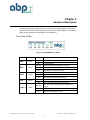
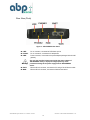
SIP EXPRESS 2-port SIP IAD User’ s Manual Version 2.0 ABP International, Inc. 1203 Crestside Dr., Ste 300 Coppell, TX 75019 Phone: (972) 831 0280 Fax : (972) 831 1416 Support:[email protected] Sales:[email protected] Website: www.abptech.com Copyright Notice © Copyright 2004 –ABP International, Inc.. All Rights Reserved. No part of this publication may be reproduced, transmitted, or transcribed in any form or by any form or by any means, electronic, or mechanical, including photocopy, recording, or any information storage and retrieval system, without prior permission in writing form from ABP International, Inc. Trademark Acknowledgment All products or service names mentioned in this document may be trademarks of the companies with which they are associated. SIP EXPRESS 2-port SIP IAD User’ s Manual - 04/01/28 2 Document # ABP-UM2004-SIP EXPRESS –v2.0 About this Manual This manual is intended for users, administrators and technicians to install, configure, operate and manage the SIP EXPRESS. This manual contains the following information: Chapter 1 - Overview provides an introduction of the device, and its related features, application usage and specifications list. Chapter 2 - Hardware Description describes and lists the important features on the front and rear panels of the device, including the description of each connector, LED, and port. Chapter 3 - Installation and Setup contains reminders when unpacking, including safety precautions, the minimum hardware and software requirements, and installation procedure. Chapter 4 - Configuring TCP/IP Protocol for Your PC lists the procedures when changing the TCP/IP protocols under several operating system environments. Chapter 5 - Introduction to Web-based Interface provides introduction to the Web-based UI, guideline for system configuration, performance monitoring, system maintenance and administration. Appendix A provides instruction for troubleshooting and diagnostics. Appendix B provides a table of acronyms used in this manual. Notes and Warnings This manual includes various Notes and Warnings, which are highlighted with graphics to indicate important information. Notes contain for your information text that corresponds to a topic. Note Warnings identify essential steps, actions, or system messages that should not be ignored. Warning SIP EXPRESS 2-port SIP IAD User’ s Manual - 04/01/28 3 Document # ABP-UM2004-SIP EXPRESS –v2.0 Radio Frequency Emissions Notice This equipment has been tested and found to comply with the limits for a Class A digital device, pursuant to Part 15 of the FCC Rules. These limits are designed to provide reasonable protection against harmful interference when operate in a commercial environment. This equipment generates, uses, and can radiate radio frequency energy and, if not installed and used in accordance with the instruction manual, may cause harmful interference to radio communications. Operation of this equipment in a residential area may cause harmful interference, in which case the user will be required to correct the interference at his expense. Safety The following information relates to the safety of installation and maintenance personnel. Read all instructions before attempting to unpack or install or operate this equipment, and before connecting the power supply. Please keep the following in mind as you unpack and install this equipment: Always follow basic safety precautions to reduce the risk of fire, electrical shock and injury to persons. To prevent fire or shock hazard, do not expose the unit to rain, moisture or install this product near water. Never spill liquid of any kind on or into this product. Never push an object of any kind into this product through module openings or empty slots, as you may damage parts. Do not attach the power supply cabling to building surfaces. Do not allow anything to rest on the power cabling or allow it to be abused by persons walking on it. To protect the equipment from overheating, do not block the slots and openings in the module housing that provide ventilation. Use caution when installing or modifying telephone lines. Never install telephone wiring during an electrical storm. Getting Technical Assistance Should you have questions or problems with your SIP EXPRESS, ABP International, is available to help you within the guidelines of our product support programs. First, check the printed or online product documentation for assistance. Then, be ready to provide the following information: SIP EXPRESS configuration Model and part number of the device Software release version # Network configuration information, such as your IP addresses and other information. The exact wording of any error messages that were reported by the SIP EXPRESS, including any error code numbers contained in those messages Your questions, or a description of the problem you are experiencing Call ABP International, for technical support SIP EXPRESS 2-port SIP IAD User’ s Manual - 04/01/28 4 Document # ABP-UM2004-SIP EXPRESS –v2.0 Table of Contents About this Manual .............................................................................................................. 3 Notes and Warnings........................................................................................................... 3 Radio Frequency Emissions Notice.................................................................................... 4 Safety ................................................................................................................................ 4 Getting Technical Assistance .............................................................................................. 4 Table of Contents ............................................................................................................... 5 Chapter 1 Overview ........................................................................................ 8 Introduction........................................................................................................................ 8 Features ............................................................................................................................ 8 Application ......................................................................................................................... 9 Specifications..................................................................................................................... 9 Chapter 2 Hardware Description ................................................................... 8 Front View (LEDs).............................................................................................................11 Rear View (Ports)............................................................................................................. 12 Chapter 3 Installation and Setup................................................................. 13 Safety Precautions........................................................................................................... 13 Preparing for Hardware Installation .................................................................................. 13 Unpacking........................................................................................................................ 13 Hardware & Software Requirements ................................................................................ 14 Installation Procedure ...................................................................................................... 14 Chapter 4 Configuring TCP/IP Protocol for Your PC ................................. 16 Introduction...................................................................................................................... 16 Windows 98/Me ............................................................................................................... 16 Windows 2000 ................................................................................................................. 16 Windows NT .................................................................................................................... 17 Chapter 5 Introduction to Web-based Interface......................................... 18 Configuring via Web Browser ........................................................................................... 18 System Functions ............................................................................................................ 20 System Status (supervisor) ......................................................................................... 20 DHCPC Status............................................................................................................ 21 PPPoE Status ............................................................................................................. 22 PPPoE Configuration ....................................................................................................... 23 WAN Configuration .......................................................................................................... 24 WAN IP....................................................................................................................... 24 Provisioning ................................................................................................................ 25 Device Mode............................................................................................................... 25 NTP ................................................................................................................................. 27 Network Time Protocol Configuration .......................................................................... 27 DHCP .............................................................................................................................. 28 LAN DHCP Configuration............................................................................................ 28 NAPT Configuration ......................................................................................................... 29 Port Forwarding .......................................................................................................... 29 IP Filter....................................................................................................................... 30 DMZ ........................................................................................................................... 31 QoS ................................................................................................................................. 32 QoS Configuration ...................................................................................................... 32 DSCP Configuration.................................................................................................... 33 VLAN............................................................................................................................... 34 VLAN Tag Configuration.............................................................................................. 34 PSTN Configuration ......................................................................................................... 35 Switch Key.................................................................................................................. 35 Digit Map .................................................................................................................... 36 SIP EXPRESS 2-port SIP IAD User’ s Manual - 04/01/28 5 Document # ABP-UM2004-SIP EXPRESS –v2.0 Provision Configuration .................................................................................................... 37 Syslog Configuration ........................................................................................................ 38 EMS Configuration........................................................................................................... 39 EMS ........................................................................................................................... 39 SNMP Community ...................................................................................................... 40 SNMP Trap Target ...................................................................................................... 41 VoIP Configuration ........................................................................................................... 42 Protocol ...................................................................................................................... 42 User ........................................................................................................................... 43 SIP ............................................................................................................................. 44 CODEC ...................................................................................................................... 45 RTP ............................................................................................................................ 46 Tone ........................................................................................................................... 47 FAX ............................................................................................................................ 48 STUN ......................................................................................................................... 49 Speed Dial .................................................................................................................. 50 Call Features .............................................................................................................. 51 Password Configuration ................................................................................................... 53 Supervisor Password .................................................................................................. 53 User Password ........................................................................................................... 54 Upgrade Configuration ..................................................................................................... 55 Firmware .................................................................................................................... 55 Configuration .............................................................................................................. 56 View ................................................................................................................................ 57 View Configuration...................................................................................................... 57 Save ................................................................................................................................ 58 Save Configuration ..................................................................................................... 58 Load Default Settings.................................................................................................. 59 Reboot............................................................................................................................. 60 Appendix A Troubleshooting and Diagnostics .......................................... 61 Appendix B Acronyms ................................................................................. 62 SIP EXPRESS 2-port SIP IAD User’ s Manual - 04/01/28 6 Document # ABP-UM2004-SIP EXPRESS –v2.0 List of Figures Figure 1 - SIP EXPRESS Typical Application............................................................................. 9 Figure 2 - SIP EXPRESS Face Panel.......................................................................................11 Figure 3 - SIP EXPRESS Rear Panel ...................................................................................... 12 Figure 4 - Installation Diagram................................................................................................. 14 Figure 5 - Web Browser Address Field .................................................................................... 18 Figure 6 - Login Window ......................................................................................................... 19 Figure7 - System Status Window............................................................................................. 20 Figure 8 - DHCPC Status Window........................................................................................... 21 Figure 9 - PPPoE Status Window ............................................................................................ 22 Figure 10 - PPPoE Configuration Window ............................................................................... 23 Figure 11 - WAN Configuration Window................................................................................... 24 Figure 12 - WAN Provision Configuration Window ................................................................... 25 Figure 13 - Device Mode Configuration Window ...................................................................... 26 Figure 14 - NTP Configuration Window.................................................................................... 27 Figure 15 - DHCP Configuration Window................................................................................. 28 Figure 16 - Port Forwarding Rule/Rule Table Window.............................................................. 29 Figure 17 - IP Filter Configuration Window .............................................................................. 30 Figure 18 - DMZ Configuration Window................................................................................... 31 Figure 19 - Qos Configuration Window.................................................................................... 32 Figure 20 - DSCP Configuration Window................................................................................. 33 Figure 21 - VLAN Tag Configuration Window........................................................................... 34 Figure 22 - PSTN Switch Key Window..................................................................................... 35 Figure 23 - PSTN Digitmap Window ........................................................................................ 36 Figure 24 - Provision Configuration Window ............................................................................ 37 Figure 25 - Syslog Configuration Window................................................................................ 38 Figure 26 - EMS Configuration Window................................................................................... 39 Figure 27 - SNMP Community Configuration Window.............................................................. 40 Figure 28 - SNMP Trap Configuration Window......................................................................... 41 Figure 29 - VoIP Protocol Configuration Window ..................................................................... 42 Figure 30 - VoIP User Configuration Window........................................................................... 43 Figure 31 - VoIP SIP Configuration Window............................................................................. 44 Figure 32 - VoIP Codec Configuration Window ........................................................................ 45 Figure 33 - VoIP RTP Configuration Window ........................................................................... 46 Figure 34 - VoIP Tone Configuration Window........................................................................... 47 Figure 35 - VoIP Fax Configuration Window ............................................................................ 48 Figure 36 - VoIP STUN Configuration Window......................................................................... 49 Figure 37 - VoIP Speed Dial Configuration Window ................................................................. 50 Figure 38 - VoIP Call Feature Configuration Window ............................................................... 51 Figure 39 - Supervisor Password Window ............................................................................... 53 Figure 40 - User Password Window ........................................................................................ 54 Figure 41 - Firmware Upgrade Window ................................................................................... 55 Figure 42 - Configuration Upgrade Window ............................................................................. 56 Figure 43 - View Configuration Window................................................................................... 57 Figure 44 - Save Configuration to Flash Window ..................................................................... 58 Figure 45 - Load Default Settings Window............................................................................... 59 Figure 46 - Reboot Window..................................................................................................... 60 SIP EXPRESS 2-port SIP IAD User’ s Manual - 04/01/28 7 Document # ABP-UM2004-SIP EXPRESS –v2.0 Chapter 1 Overview The VoIP gateway delivers voice information over the Internet Protocol instead of via traditional PSTN. This benefits small offices and work-at-home users with high-speed broadband Internet access and toll-free service. In addition, the VoIP gateway features the PSTN back-up line, offering users to use PSTN phone line when the VoIP service is not available or during power outage. Furthermore, the VoIP gateway provides GUI configuration, allowing users to easily make settings via web browser. Also, it supports firmware upgrade via TFTP. Introduction The SIP EXPRESS 2-port SIP IAD (Integrated Access Device) is an external standalone device, which can provide a cost-effective voice communication through the Internet. The SIP EXPRESS can establish the voice channel by adopting SIP (Session Initiation Protocol) signaling after registering to a SIP proxy server. The SIP EXPRESS can connect directly to phones, fax machines, PBX, and internet without extra equipment and setup. With the Ethernet interface of the SIP EXPRESS SIP IAD connected to another device with a WAN interface (e.g. ADSL﹐…), the SIP EXPRESS SIP IAD can provide toll quality voice communication in terms of voice quality and reliability for the users. Also, the SIP EXPRESS integrates two kinds of data service operation mode to provide the best convenience and flexibility for users﹐in which﹐one is gateway mode and the other is Transparent Bridge mode. The gateway mode targets user who has been enjoying Internet service from ISP, and would like to subscribe to VoIP service provider’ s telephony services. The IAD would be deployed at subscriber’ s home, with WAN interface connecting to ADSL, which subscriber’ s would be connecting to IAD’ s LAN interface In such kind of scenario, the IAD could deliver voice services function, as well as the broadband router function. On the other hand, the Transparent Bridge mode is very similar to the gateway mode. Subscriber had been using broadband router. The IAD being deployed would be connecting, through its WAN interface, to broadband router’ s LAN interface. Subscriber’ s PC may connect to IAD’ s LAN interface. Then IAD could deliver voice services function, and would bridge traffic from PC connecting to its LAN interface. Features The SIP EXPRESS supports the following features: Provide toll quality voice over IP network Cost-Effective edge device that enables high-value IP phone Two 10/100 Ethernet connection for corporation LAN or broadband access (WAN) Simple configuration and setup Remotely manageable and upgradeable Automatic switch to PSTN line for emergency calls SIP EXPRESS 2-port SIP IAD User’ s Manual - 04/01/28 8 Document # UM2004-SIP EXPRESS -v1.0 Application Figure 1 - SIP EXPRESS Typical Application Specifications Voice Features Auto registration to SIP Registrar at power-up and periodic RE-registration Digest (MD5) Proxy/Register authentication Superior audio quality Supports G.711, G.729A , G.723.1 Codec Supports Modem, T.38 FAX, in-band and out-of-band DTMF (RFC2833) Supports adaptive jitter buffer control & Echo cancellation (G.168) Supports Silence Suppression, VAD (Voice Activity Detection), CNG (Comfort Noise Generation) Supports configurable gain/loss control Digit Map dial-plan support for switching to PSTN line Supports loop start and polarity reversal PSTN loop through backup for power outage Network Interface Two RJ45 jacks (WAN & LAN 10/100 based-T interface Three RJ11 jacks (1 PSTN & 2 analogue phone lines) Supporting Protocol SIP 2.0, TCP/UDP/IP, RTP/RTCP, HTTP, ICMP, ARP, DNS, DHCP, NTP/SNTP, TFTP protocols ABP Technology NAT/Firewall Traversal IETF STUN SIP EXPRESS 2-port SIP IAD User’ s Manual - 04/01/28 9 Document # ABP-UM2004-SIP EXPRESS –v2.0 OA&M Access security (Supervisor and User) by Username/Password authentication Manual Web GUI Provisioning for easy configuration User enable/disable control for WAN access Auto-provisioning (automated centralized configuration file) Soft reset to factory default configuration EMS (Element Management System) support Local software upgrade through Web interface & console Remote software upgrade through TFTP System log server support Country Tone Fit PRC, HK and Taiwan Voice Calling Features Caller ID Display (Calling Number or Name) Call Waiting Call Hold (and Retrieve) Call Transfer with/without Consultation Call Forwarding Always Call Forwarding Busy Call Forwarding On no Answer Speed Dial (user configurable) Gateway Mode Support WAN side DHCP client access WAN side PPPoE client access Static IP support IP sharing support Layer 2 priority on MG traffic over LAN port traffic to uplink WAN interface Uplink Layer 3 DiffServ marking QoS NAPT (1-to-many address translation) DHCP Server function (up to 10 concurrent clients) Static LAN Client IP address support DMZ for specified LAN IP address IP filtering and TCP/UDP port forwarding Configurable mode of operation for LAN port traffic (Trusted vs. Un-trusted) – Preserve or Remark DSCP settings Transparent Bridge Mode Support WAN side DHCP client access WAN side PPPoE client access Static IP support Transparent bridging for LAN port traffic to uplink interface Traffic access prevention on LAN interface Layer 2 priority on MG traffic over LAN port traffic to uplink WAN interface General Information Dimensions: 190 x 130 x 130 mm Power Consumption: 12w typical EMI Certification: FCC Part15 Class B Safety Certification: UL 1950, En60950 SIP EXPRESS 2-port SIP IAD User’ s Manual - 04/01/28 10 Document # ABP-UM2004-SIP EXPRESS –v2.0 Chapter 2 Hardware Description This chapter describes the appearance of the ABP Technology SIP EXPRESS. Structures of the front and back panels will be introduced accordingly. The SIP EXPRESS is a modularized design for easy deployment, management, and maintenance. Front View (LEDs) Figure 2 - SIP EXPRESS Face Panel LED PWR Color Green Status On When the VoIP gateway is powered on Off No power supply Blinking WAN Green VoIP Green Green When WAN connection is established Off When there is no WAN connection Green SIP EXPRESS 2-port SIP IAD User’ s Manual - 04/01/28 When data is being transmitted or received On When Ethernet connection is established Off When there is no Ethernet connection On When VoIP telephone service is ready Off When VoIP telephone service is not ready Blinking LINE 1, 2 When data is being transmitted or received On Blinking ENET Description When there is an incoming call (the telephone is ringing) On When the telephone is in use Off Switches to PSTN back-up line 11 Document # UM2004-SIP EXPRESS -v1.0 Rear View (Ports) Figure 3 - SIP EXPRESS Rear Panel LINE: PHONE: PWR: Warning ENET: WAN: RJ-11 connector, connected to PSTN back-up line RJ-11 connectors, connected to IP telephones Power connector, connected to the power adapter packaged with the VoIP gateway Use only the specified voltage required by the power adapter of SIP EXPRESS. Faulty or improper voltage input may cause permanent damage to the power supply and the SIP EXPRESS device. Ethernet RJ-45 connector, connected to PC using a RJ-45 Ethernet cable Ethernet RJ-45 connector, connected to WAN access device SIP EXPRESS 2-port SIP IAD User’ s Manual - 04/01/28 12 Document # ABP-UM2004-SIP EXPRESS –v2.0 Chapter 3 Installation and Setup This chapter describes packaging, preparation for hardware installation, hardware installation procedures, power up and initial setup. It also provides the safety tips to observe in order to avoid ESD and other damages to the device. Safety Precautions Use only the specified power adapter (output voltage: 12VDC/1A) and make sure the power adaptor’ s input power voltage is the same as that of your local power outlet. Always unplug the power cable before installing or removing this product. Carefully examine your working area for possible hazards such as moist floors, ungrounded power extension cables, and missing safety grounds. Do not install this product during a lighting storm. Do not install this product at a wet location. Electrostatic discharge (ESD) damage can cause complete or intermittent system failures. Using an anti-static strap when handling this product will minimize the possibility of ESD damage. Unplug this product from the wall outlet before cleaning. Do not use liquid cleaners or aerosol cleaners. The openings along the sides and top portion of this product are for ventilation purposes. To protect the device from overheating, do not block or cover these openings. Never disassemble this product. Preparing for Hardware Installation You should carefully read the following sections before installing the SIP EXPRESS. The succeeding sections discuss unpacking, hardware & software requirements, installation procedure, and the power-up and initialization steps that are important for you to know when you perform the installation of this unit. Unpacking Carefully unpack your package and make sure that you have the following items. One VoIP Residential Gateway Two RJ-11 telephone lines for the first telephone One RJ-11 telephone line for PSTN back-up use (optional) One RJ-45 Ethernet cable One power adapter One user’ s manual CD If you find anything missing, mismatched or damaged, promptly contact your dealer who you purchased your product from for help. SIP EXPRESS 2-port SIP IAD User’ s Manual - 04/01/28 13 Document # ABP-UM2004-SIP EXPRESS –v2.0 Hardware & Software Requirements The items listed below are the minimum hardware and software requirements needed before commencing with the installation procedure. One RJ-45 Broadband Internet connection via cable modem or ADSL modem One PC with 10Mbps, 100Mbps, or 10/100 Mbps Ethernet card installed TCP/IP protocol for each PC Microsoft Internet Explorer 4.0 or later (5.0 is strongly recommended for web configuration) One standard touch-tone telephone Subscribe to a VoIP service provider for VoIP services Modem or ADSL modem Installation Procedure Figure 4 - Installation Diagram LINE: Plug one end of the RJ-11 telephone line into the LINE port and plug the other end into the phone port of the splitter. Then connect the splitter to the phone socket in the wall using a RJ-11 telephone line. The LINE port is for back-up use. The telephone is using VoIP service by default. However, if the VoIP gateway loses WAN connection or the VoIP function is not available, the VoIP gateway will make the telephone to use PSTN (Public Switched Telephone Network) service. SIP EXPRESS 2-port SIP IAD User’ s Manual - 04/01/28 14 Document # ABP-UM2004-SIP EXPRESS –v2.0 PHONE: Plug one end of the RJ-11 telephone line into the PHONE port and plug the other end into the phone socket on a telephone set. PWR: Plug one end of the power adapter into the PWR port and plug the other end into an electric outlet in the wall. Warning Use only the specified voltage required by the power adapter of SIP EXPRESS. Faulty or improper voltage input may cause permanent damage to the power supply and the SIP EXPRESS device. ENET: Plug one end of the RJ-45 Ethernet cable into the ENET port and plug the other end into the Ethernet socket of NIC on your PC. WAN: Plug one end of the RJ-45 Ethernet cable into the WAN port and plug the other end into the Ethernet port of the Internet service device, such as the cable modem or ADSL modem. Then connect the cable modem or ADSL modem to the modem port of the splitter using a RJ-11 telephone line. Power-up and Initialization Before operating the ABP Technology SIP EXPRESS, check if the WAN port, LAN port and phone port are properly connected to the right devices. 1. Plug the power cable to initialize the gateway. Warning Use only the specified voltage required by the power adapter of SIP EXPRESS. Faulty or improper voltage input may cause permanent damage to the power supply and the SIP EXPRESS device. 2. The gateway will automatically launch its self-testing process. Wait for a few seconds for the gateway to complete the process. When initialization is complete, the PWR LED will light steadily. SIP EXPRESS 2-port SIP IAD User’ s Manual - 04/01/28 15 Document # ABP-UM2004-SIP EXPRESS –v2.0 Chapter 4 Configuring TCP/IP Protocol for Your PC This chapter explains the procedures when configuring the TCP/IP protocols of your PC under different operating system environments. It is mandatory that you follow the steps listed for the device to operate normally. Introduction To configure and communicate with this device, each PC on your LAN must install TCP/IP protocol. If you enable static IP addressing, make sure your PC resides in the same subnet with this device’ s LAN port. In bridge mode with the WAN side of the TA in DHCP mode, the default IP Address is 192.168.100.1 and default subnet mask: 255.255.255.0 once the PC connects to the WAN side. In gateway mode, the IP Address of the LAN side is 192.168.0.1 and the subnet mask is 255.255.255.0. The TA is set to bridge mode by default. Windows 98/Me 1. From the Start menu, click Settings, and then click Control Panel. 2. Double-click Network. 3. On the Configuration tab, check if TCP/IP protocol is installed on the components list. 4. If yes, go to Step 8. If no, then click Add. 5. Highlight Protocol and click Add. 6. Select Microsoft from the Manufactures list and select TCP/IP from the Network Protocols list. 7. Click OK. You will see TCP/IP displayed on the network components list. 8. Highlight TCP/IP and click Properties. 9. If the TA is in bridge mode, go to step 10. If the TA is in gateway mode, go to step 12 10. Select the IP Address tab and check Specify an IP address. 11. Set IP address as 192.168.100.100, Subnet mask as 255.255.255.0 and press OK. 12. Set IP address to Get an IP address automatically. Windows 2000 1. From the Start menu, click Settings, and then click Network and Dial-up Connections. 2. Double-click Local Area Connection. 3. Click Properties. 4. Click Internet Protocol (TCP/IP) and then click b. 5. If the TA is in bridge mode, go to step 6. If the TA is in gateway mode, go to step 8 6. Check Use the following IP address. 7. Set IP address as 192.168.100.100, Subnet mask as 255.255.255.0 and press OK. 8. Set IP address to Get an IP address automatically. SIP EXPRESS 2-port SIP IAD User’ s Manual - 04/01/28 16 Document # ABP-UM2004-SIP EXPRESS –v2.0 Windows NT 1. From the Start menu, click Settings, and then click Control Panel. 2. Double-click Network. 3. On the Protocol tab, check if TCP/IP protocol is installed on the components list. 4. If yes, go to Step 7. If no, then click Add. 5. Highlight TCP/IP Protocol and click OK. 6. Select TCP/IP Protocol and click Properties. 7. When Information Message appears, click OK. 8. If the TA is in bridge mode, go to step 9. If the TA is in gateway mode, go to step 11. 9. On the IP Address tab, check Specify an IP address. 10. Set IP address as 192.168.100.100, Subnet mask as 255.255.255.0 and press OK. Go to step 12. 11. Set IP Address to Get an IP Address automatically. Go to step 12. 12. When asked to restart your computer, click Yes. SIP EXPRESS 2-port SIP IAD User’ s Manual - 04/01/28 17 Document # ABP-UM2004-SIP EXPRESS –v2.0 Chapter 5 Introduction to Web-based Interface This chapter explains how to configure and manage the ABP Technology SIP EXPRESS using the Web-based Interface. The Web-based Interface provides comprehensive system management scheme, including system configuration, performance monitoring, system maintenance and administration. You may use a Web browser to access the Web-based Interface. The Web-based interface supports: Status PPPoE Status DHCP Status WAN Configuration NTP Configuration Gateway Mode Settings QoS Configuration PSTN Configuration Provision Configuration Syslog Configuration EMS Configuration VoIP Configuration Password Firmware Upgrade View Configurations Save Configuration Reboot System Configuring via Web Browser Before accessing the Web-based Interface, you need to launch a Web browser on the management host with the default IP address http://192.168.100.1. The management host should use the IP address within the same subnet as SIP EXPRESS gateway (e.g. 192.168.100.100). 1. Connect this device to your PC using an Ethernet cable. 2. Plug one end of the power adapter into the PWR port of this device and plug the other end into an electric outlet in the wall. 3. Open the web browser. 4. Enter the default IP address 192.168.100.1 of this device in bridge mode or the IP address 192.168.0.1 in gateway mode in the Address field to access the web configuration menu. Figure 5 - Web Browser Address Field SIP EXPRESS 2-port SIP IAD User’ s Manual - 04/01/28 18 Document # ABP-UM2004-SIP EXPRESS –v2.0 Logging on to the Web-based Interface When you want to set the configuration of the VoIP gateway, you must Login first. Figure 6 - Login Window Item Description USER NAME Enter the user name to login. The name can be user or supervisor. PASSWORD Enter the password to login. The password for user is “ 12345”and the password for supervisor is “ ABP Technology” . The supervisor password offers the user full authority of the device and its configuration settings upon entering the valid password code. On the other hand, encryption of the user password restricts the user’ s authority to only a limited number of configuration settings. Note SIP EXPRESS 2-port SIP IAD User’ s Manual - 04/01/28 19 Document # ABP-UM2004-SIP EXPRESS –v2.0 System Functions System Status (supervisor) Upon entering the user name and password, the Web-configuration page will prompt you with the System Status. This screen contains Board ID, Firmware Version, Web UI Version, MAC Address, and VoIP Service Status, all described on the table below. Figure7 - System Status Window Item Description Board ID Displays the part number of the VoIP gateway and customer name Firmware Version Displays the installed firmware version Web UI Version Displays the current Web UI version MAC Address Displays the unique hardware number of the VoIP gateway VoIP Service Status Displays the connection status of the VoIP gateway SIP EXPRESS 2-port SIP IAD User’ s Manual - 04/01/28 20 Document # ABP-UM2004-SIP EXPRESS –v2.0 DHCPC Status If DHCP is enabled, the DHCPC Status page will display WAN IP Address, WAN Subnet Mask and Gateway Address, etc. Figure 8 - DHCPC Status Window Item Description IP The IP Address of the VoIP gateway as seen by external users on the Internet. (Assigned automatically by your ISP) Subnet Mask The Subnet Mask of the VoIP gateway as seen by external users on the Internet. (Assigned automatically by your ISP) Gateway The Gateway Address of the VoIP gateway as seen by external users on the Internet. (Assigned automatically by your ISP) DNS1 The IP Address of Domain Name Server (Assigned automatically by your ISP) DNS2 The IP Address of Domain Name Server (Assigned automatically by your ISP) NTP Server The IP Address of NTP Server (Assigned automatically by your ISP) Provision Server The IP Address of Prevision Server (Assigned automatically by your ISP) SIP EXPRESS 2-port SIP IAD User’ s Manual - 04/01/28 21 Document # ABP-UM2004-SIP EXPRESS –v2.0 PPPoE Status If you enable PPPoE mode, you can check the status by clicking PPPoE Status. Figure 9 - PPPoE Status Window Item Description Service Name Specifies the different service group name. AC Name Indicates to use specific server. Local IP The Client IP Address. Remote IP The Service IP Address. DNS1 The IP Address of Domain Name Server DNS2 The IP Address of Domain Name Server WIN1 The IP Address of WIN Server WIN2 The IP Address of WIN Server SIP EXPRESS 2-port SIP IAD User’ s Manual - 04/01/28 22 Document # ABP-UM2004-SIP EXPRESS –v2.0 PPPoE Configuration If you select PPPoE to get WAN IP Address of the VoIP gateway, you need to enter the User name and Password provided by your ISP. Figure 10 - PPPoE Configuration Window SIP EXPRESS 2-port SIP IAD User’ s Manual - 04/01/28 23 Document # ABP-UM2004-SIP EXPRESS –v2.0 WAN Configuration WAN IP You can decide the method to obtain the WAN IP address of the VoIP gateway by selecting one of the following modes. After the gateway is restarted, the settings you have made will take effect. Figure 11 - WAN Configuration Window Item Description Static IP Address The IP address of the WAN side is assigned by the user. IP The IP address of the WAN side. Mask The subnet mask of the WAN side. Gateway The IP address of the gateway in WAN side. DNS1 The IP Address of Domain Name Server in WAN side DNS2 The IP Address of Domain Name Server in WAN side DHCP The IP Address of the WAN side is assigned by the DHCP server. PPPoE The IP Address of the WAN side is assigned by the DHCP server. SIP EXPRESS 2-port SIP IAD User’ s Manual - 04/01/28 24 Document # ABP-UM2004-SIP EXPRESS –v2.0 Provisioning If Status is off, the user can’ t connect to the web server from the WAN side on the device. On the contrary, when it is on, the user can connect the web server. Figure 12 - WAN Provision Configuration Window Device Mode If the Device Mode is Gateway, NAPT is enabled. On the contrary, it’ s Bridge, NAPT is disabled. SIP EXPRESS 2-port SIP IAD User’ s Manual - 04/01/28 25 Document # ABP-UM2004-SIP EXPRESS –v2.0 Figure 13 - Device Mode Configuration Window SIP EXPRESS 2-port SIP IAD User’ s Manual - 04/01/28 26 Document # ABP-UM2004-SIP EXPRESS –v2.0 NTP Network Time Protocol Configuration The VoIP date/time can with NTP server synchronization, and makes the renewal by the Expires value. Figure 14 - NTP Configuration Window Item Description NTP Server Specifies the IP address of NTP Server Expires Specifies the value for renewal timer Time Zone Specifies time zone SIP EXPRESS 2-port SIP IAD User’ s Manual - 04/01/28 27 Document # ABP-UM2004-SIP EXPRESS –v2.0 DHCP LAN DHCP Configuration If the device mode is gateway mode, we support DHCP Server on LAN side. You can set the Status, Last IP and Mode etc. on this page. After you make the settings, click OK for the settings to immediately take effect. Figure 15 - DHCP Configuration Window Item Description Status The DHCP Server is enabled or disabled. Last IP The last IP can be assigned by the DHCP server. Mode The network settings assigned to the DHCP Client is Auto mode or Manual Mode. In Auto mode, the network settings are from the WAN side. In Manual mode, the network settings are from the user’ s input in this page. DNS You can manually set the value in Manual mode or it takes the value from WAN side in Auto mode. Domain You can manually set the value in Manual mode or it takes the value from WAN side in Auto mode. Least time The least time of the DHCP client to holding the network settings. The value is useful in Auto mode. SIP EXPRESS 2-port SIP IAD User’ s Manual - 04/01/28 28 Document # ABP-UM2004-SIP EXPRESS –v2.0 NAPT Configuration Port Forwarding You can add or delete Port Forwarding Rule to the device in Gateway mode. When the packet goes into the VoIP gateway, if the port of the packet matches the port of port-forwarding rule, the packet will be forwarded to the private IP address configured of the matched rule. Figure 16 - Port Forwarding Rule/Rule Table Window Item Description Tcp/udp/both Select if you want to forward the packet based on tcp, udp or both. Forward Port The tcp or udp port number for which you want to check against. To Private IP The IP Address of the pc in the LAN side is forwarding to. ID The ID of the port forwarding rule is to be deleted. SIP EXPRESS 2-port SIP IAD User’ s Manual - 04/01/28 29 Document # ABP-UM2004-SIP EXPRESS –v2.0 IP Filter You can add or delete IP Filter Rule to the device in Gateway mode. When the packet goes into the VoIP gateway, the packet will be blocked if the source IP of the packet matches the rule of IP Filter. Figure 17 - IP Filter Configuration Window Item Description Public IP The Public IP Address is to be filtered. ID The ID of the IP Filter rule is to be deleted. SIP EXPRESS 2-port SIP IAD User’ s Manual - 04/01/28 30 Document # ABP-UM2004-SIP EXPRESS –v2.0 DMZ You can enable or disable DMZ and specify the IP address of DMZ in Gateway mode. When the packet goes into the VoIP gateway, the packet will be transferred to the DMZ if packet is not filtered, not port-forwarded, and not matched for the NAPT binding. Figure 18 - DMZ Configuration Window Item Description DMZ The DMZ is disabled or enabled. DMZ IP address The IP address of the DMZ. SIP EXPRESS 2-port SIP IAD User’ s Manual - 04/01/28 31 Document # ABP-UM2004-SIP EXPRESS –v2.0 QoS QoS Configuration You can decide the QoS type of the packets coming out from the VoIP gateway. If the type of QoS is DiffServ, you can also specify the different values for Signal DSCP and Media DSCP. Both ToS and DSCP QoS are supported for the VoIP packets sending out from the VoIP gateway. Figure 19 - Qos Configuration Window Item Description Qos Type The type of Qos can be disabled, DiffServ or Tos. Tos The value of Tos is usually between 0~15. Signal DSCP The value of Differentiated Services Code Point is for Signal. Media DSCP The value of Differentiated Services Code Point is for Media SIP EXPRESS 2-port SIP IAD User’ s Manual - 04/01/28 32 Document # ABP-UM2004-SIP EXPRESS –v2.0 DSCP Configuration You can set the DSCP mode to Trusted or Un-Trusted. This DSCP mode of operations is supported for PCs traffic from LAN interface. If it is set to Trusted Mode, the TA will preserve DSCP settings from LAN interface. If it is set to Un-Trusted mode, the TA will remark to DSCP DE before forwarding to Uplink interface. Figure 20 - DSCP Configuration Window SIP EXPRESS 2-port SIP IAD User’ s Manual - 04/01/28 33 Document # ABP-UM2004-SIP EXPRESS –v2.0 VLAN VLAN Tag Configuration You can enable or disable VLAN Tag function on SIP EXPRESS, Figure 21 - VLAN Tag Configuration Window Item Description VLAN Tag The VLAN Tag is enabled or disable. Data Priority Specifies the priority value of data traffic. (From 0 to 7) Data VLAN ID Specifies the VLAN ID for data traffic. (From 4 to 4095) Voice Priority Specifies the priority value of voice traffic. (From 0 to 7) Voice VLAN ID Specifies the VLAN ID for voice traffic. (From 1 to 4095) SIP EXPRESS 2-port SIP IAD User’ s Manual - 04/01/28 34 Document # ABP-UM2004-SIP EXPRESS –v2.0 PSTN Configuration Switch Key This functions allows user to set PSTN switch number. Normally, your telephone is using VOIP service except the VOIP service is not available. However, you can switch VoIP mode to PSTN mode by entering a 4-digit entry. “ 0000”is the default value. Figure 22 - PSTN Switch Key Window SIP EXPRESS 2-port SIP IAD User’ s Manual - 04/01/28 35 Document # ABP-UM2004-SIP EXPRESS –v2.0 Digit Map This function allows user to set the Digit Map. Normally, your telephone is using VOIP service except the VOIP service is not available. However, you can set up a list of numbers with specific prefix and total length to switch from VoIP mode to PSTN mode. Figure 23 - PSTN Digitmap Window Item Description Prefix Enter the prefix of the telephone number. The maximum length is 5 digits. Length Enter the total length of the telephone number. The length is ranged from 0~64. “ 0”means the length is not fixed. Add/Modify Add or modify your desired prefix and length of the telephone number. Delete Delete an existing prefix and length of the telephone number from the Digit Map Table Refresh Press this button will show new changes SIP EXPRESS 2-port SIP IAD User’ s Manual - 04/01/28 36 Document # ABP-UM2004-SIP EXPRESS –v2.0 Provision Configuration The SIP EXPRESS gateway supports Provisioning Configuration mechanism to get and set the gateway configuration parameters. When the gateway downloads the configuration file from Provision server, it will compare the downloaded parameters and existing local parameters. If the former is newer, the existing local setting parameters will be overwritten and the downloaded setting parameters will be written into the FLASH memory. This feature sets provision configurations including server address, server port number, group and expiry time. After you make the settings, click OK and then Reboot for the new settings to take effect. Figure 24 - Provision Configuration Window Item Description Server Address The IP Address of Provision Server. Enter the value provided by your ISP. Server Port The receiving port number of Provision Server. Enter the value provided by your ISP. Group Enter the string for different user group. The maximum length is 64. Enter the value provided by your ISP. Expires The valid period for this device’ s IP Address assigned by DHCP server or PPPoE server. The unit is second. Enter the value provided by your ISP. SIP EXPRESS 2-port SIP IAD User’ s Manual - 04/01/28 37 Document # ABP-UM2004-SIP EXPRESS –v2.0 Syslog Configuration The SIP EXPRESS VoIP gateway supports Syslog. Syslog is used to send UDP packets via Syslog port (514) and keep messages in the Log Server. Figure 25 - Syslog Configuration Window Item Description Server Address Specify the IP Address of Syslog server. Server Port Specify the port number of Syslog server. SIP EXPRESS 2-port SIP IAD User’ s Manual - 04/01/28 38 Document # ABP-UM2004-SIP EXPRESS –v2.0 EMS Configuration EMS This VoIP gateway supports EMS management function. Users can set the EMS configuration including Server Address, Server Port, Community and expiration time. Figure 26 - EMS Configuration Window Item Description Server Address Specifies the IP address of EMS server Server Port Specifies the Port number of EMS Server Community Specifies the Community used to EMS Server Expires Specifies the valid period of the VoIP gateway managed by EMS Server. The unit is second. SIP EXPRESS 2-port SIP IAD User’ s Manual - 04/01/28 39 Document # ABP-UM2004-SIP EXPRESS –v2.0 SNMP Community The SIP EXPRESS VoIP gateway supports SNMP agent. Users can use EMS to manage the VoIP gateway via SNMP protocol. After you make the settings, click OK and then Reset the device for the settings to take effect. Figure 27 - SNMP Community Configuration Window Item Description Set Community The Community is used when the user sets some oids. Get Community The Community is used when the user gets some oids. Trap Community The Community is used when the user process the traps. SIP EXPRESS 2-port SIP IAD User’ s Manual - 04/01/28 40 Document # ABP-UM2004-SIP EXPRESS –v2.0 SNMP Trap Target The SIP EXPRESS VoIP supports 4 Trap targets. You can specify different IP and Port to receive the traps sent from the VoIP gateway. After you make the settings, click OK and then Reset the device for the new settings to take effect. Figure 28 - SNMP Trap Configuration Window Item Description Trap The traps will be sent or not. IP Specify the IP Address to which the traps of the VoIP gateway will send. Port Specify the Port to which the traps of the VoIP gateway will send. SIP EXPRESS 2-port SIP IAD User’ s Manual - 04/01/28 41 Document # ABP-UM2004-SIP EXPRESS –v2.0 VoIP Configuration Protocol The screen allows you to select the VoIP protocol between H.323, SIP, and MGCP. In this version, SIP EXPRESS supports SIP only. Figure 29 - VoIP Protocol Configuration Window SIP EXPRESS 2-port SIP IAD User’ s Manual - 04/01/28 42 Document # ABP-UM2004-SIP EXPRESS –v2.0 User This screen allows you to set the user information such as username, password and display name. You should obtain the values from your service provider for services. After you make the settings, click OK and then Reboot for the new settings to take effect. Figure 30 - VoIP User Configuration Window Item Description Username Specifies the name (or phone name) of the user Password Specifies the password of the user Display name Specifies the displayed user number SIP EXPRESS 2-port SIP IAD User’ s Manual - 04/01/28 43 Document # ABP-UM2004-SIP EXPRESS –v2.0 SIP This screen allows you to make SIP configurations including local port, SIP proxy server address and port number, Registrar server address and port number, expiry time, SIP domain and subject. After you make the settings, click OK and then Reboot for the new settings to take effect. Figure 31 - VoIP SIP Configuration Window Item Description Local Port Specifies the port number of the SIP stack. 5060 is the default port number. Proxy Address Specifies the IP address of SIP proxy server Proxy Port Specifies the port number of SIP proxy server Registrar Address Specifies the IP address of Registrar server. Registrar server is often the same as SIP proxy server Registrar Port Specifies the port number of Registrar server. Outbound Proxy Address Specifies the IP address of the outbound proxy server (ie. example NATPASS™) Outbound Proxy Port Specifies the port number of outbound proxy server Expires “ Expires”specifies the period (in seconds) that the VoIP gateway sends Registration message to Registrar server. This is to help check the connection status in case the VoIP gateway is accidentally disconnected from the Registrar server. SIP Domain Specifies the domain name to which the TA is assigned to by the service provider Subject Specifies the content of the subject header in outgoing INVITE message. This is used to indicate the title of the call. SIP EXPRESS 2-port SIP IAD User’ s Manual - 04/01/28 44 Document # ABP-UM2004-SIP EXPRESS –v2.0 CODEC This screen allows you to set CODEC configurations including Codec Rate, Preferred Codec, and VAD. After make the settings, click OK and then Reset for the new settings to take effect. Figure 32 - VoIP Codec Configuration Window Item CODEC Rate Description “ CODEC rate”specifies the packetization time (in milliseconds). This value is from 10 to 30 Preferred CODEC Specifies the preferred method of voice compression. VAD Voice Activity Detection feature. Enabled: sending packets only while the user is speaking. This will save the bandwidth but cause the time delay. Disabled: sending packets no matter the user is speaking or not. This will improve the voice quality to be more smoothly but increase more traffic load. SIP EXPRESS 2-port SIP IAD User’ s Manual - 04/01/28 45 Document # ABP-UM2004-SIP EXPRESS –v2.0 RTP This screen allows user to set RTP port number. After make the settings, click OK and then Reset for the new settings to take effect. Figure 33 - VoIP RTP Configuration Window Item RTP port Description Specifies the RTP port number to the far end device that the voice packet should be sent on this port number to the TA. SIP EXPRESS 2-port SIP IAD User’ s Manual - 04/01/28 46 Document # ABP-UM2004-SIP EXPRESS –v2.0 Tone This screen allows user to set the tone configurations including Rx gain, Tx gain, ringing tone, dial tone, busy tone, ring back tone and call waiting tone. After make the settings, click OK and then Reset for the new settings to take effect. Figure 34 - VoIP Tone Configuration Window Item Description Rx Gain Adjusts the receiving audio gain to be higher or lower Tx Gain Adjust the transmitting audio gain to be higher or lower Ring Sets the ringing cadence (in milliseconds). <ontime, offtime> Dial Tone Sets the dial tone pattern <ontime, offtime (in milliseconds), freq1, freq2 (in Hz)> Busy Tone Sets the busy tone pattern <ontime, offtime (in milliseconds), freq1, freq2 (in Hz)> Ring Back Tine Sets the ring back tone pattern <ontime, offtime (in milliseconds), freq1, freq2 (in Hz)> Call Waiting Tone Sets the call waiting tone pattern <ontime, offtime (in milliseconds), freq1, freq2 (in Hz)> SIP EXPRESS 2-port SIP IAD User’ s Manual - 04/01/28 47 Document # ABP-UM2004-SIP EXPRESS –v2.0 FAX This screen allows user to set the port number for sending/receiving T.38 packets. T.38 protocol supports data-resending mechanism in case of any missing data during transmission. After make the settings, click OK and then Reset for the new settings to take effect. Figure 35 - VoIP Fax Configuration Window Item Description T.38 Fax Enables or disables the T.38 function T.38 Port Specifies the T.38 port number for sending/receiving T.38 packets SIP EXPRESS 2-port SIP IAD User’ s Manual - 04/01/28 48 Document # ABP-UM2004-SIP EXPRESS –v2.0 STUN This screen allows user to set NAT address, STUN server address, STUN server port, local port and expiry time. After make the settings, click OK and then Reset for the new settings to take effect. Figure 36 - VoIP STUN Configuration Window Item Description NAT Address Statically specifies the IP address of the TA for VoIP if it is installed behind a NAT. The IP address is the WAN side IP address from the NAT device. STUN Server Address Specifies the IP address of STUN server (Simple Traversal of User Datagram) STUN Server Port Specifies the port number of STUN server Local Port Specifies the local port number of STUN client Expires Specifies the period (in seconds) that the VoIP gateway sends STUN message to STUN server. This is to help check the connection status in case the VoIP gateway is accidentally disconnected from STUN server. User can dynamically set the IP address for VoIP using STUN. Please set the NAT address to 0 if STUN method is used. Vice versa, if NAT address is used, set the STUN Server Address to 0. Note SIP EXPRESS 2-port SIP IAD User’ s Manual - 04/01/28 49 Document # ABP-UM2004-SIP EXPRESS –v2.0 Speed Dial The speed dial is used to set up a list of telephone numbers and SIP addresses of the call parties you wish to call. Figure 37 - VoIP Speed Dial Configuration Window Item Description Number Specifies the abbreviated number of the call party. Destination Enter the SIP address (or PSTN number) of the call party (Example: [email protected]) Add/Modify Add or modify the telephone number and SIP address of the call party. Delete Delete an existing telephone number and SIP address of the call party from the Speed Dial Table. Refresh Pressing this button will show new changes. SIP EXPRESS 2-port SIP IAD User’ s Manual - 04/01/28 50 Document # ABP-UM2004-SIP EXPRESS –v2.0 Call Features Set Call features for SIP IAD including call Hold, call Waiting, call Forwarding. After you make the settings, click OK and then Save, Reset to take effect. Figure 38 - VoIP Call Feature Configuration Window Item Description Call Hold Enable or Disable Call Hold feature. User may use flash key to hold the other party. Once call hold is disabled, call waiting is also disabled. Call Waiting Enable or Disable Call Waiting feature. If a user is talking with one party and the other call come in, a user can use flash key to switch to either party. If a user want to disconnect with one party and talk with the other one, a user need to enter disconnect code Call Transfer Enables or disables Call Transfer. There are 2 types of Call Transfer: With Consultation: transfers a call to the 3rd user with consultation prior to doing it Without Consultation: transfers a call to the 3rd user without consultation prior to doing it General Feature Code Disconnects the call after pressing a specified key suite Call Forward Enable or Disable Call Forwarding. There are 3 types Call Forwarding. Always: Unconditionally forward a call to the destination that user configured. Busy: Forward a call to the destination that user configured only when the line is busy SIP EXPRESS 2-port SIP IAD User’ s Manual - 04/01/28 51 Document # ABP-UM2004-SIP EXPRESS –v2.0 No-Answer: Forward a call to the destination that user configured when nobody answer this call after # of rings SIP EXPRESS 2-port SIP IAD User’ s Manual - 04/01/28 52 Document # ABP-UM2004-SIP EXPRESS –v2.0 Password Configuration Supervisor Password The password will be used for authentication. It is recommended that you reset the password for administrator security. Figure 39 - Supervisor Password Window Item Description Old Password Enter the predefined password. New Password Enter the new password. Confirm Password Re-enter the new password in this field to ensure it is correct.. SIP EXPRESS 2-port SIP IAD User’ s Manual - 04/01/28 53 Document # ABP-UM2004-SIP EXPRESS –v2.0 User Password The password will be used for authentication. It is recommended that you reset the password for user security. Figure 40 - User Password Window Item Description Old Password Enter the predefined password. New Password Enter the new password. Confirm Password Re-enter the new password in this field to ensure it is correct.. SIP EXPRESS 2-port SIP IAD User’ s Manual - 04/01/28 54 Document # ABP-UM2004-SIP EXPRESS –v2.0 Upgrade Configuration Firmware This feature allows you to upgrade the firmware on the VoIP gateway from the web browser. The firmware on the VoIP gateway is stored on FLASH ROM. To upgrade firmware, you need to download the firmware to your local computer first. Once the new firmware is downloaded, click Browse to locate the new firmware on your computer. Then click Upgrade to complete the process. Figure 41 - Firmware Upgrade Window SIP EXPRESS 2-port SIP IAD User’ s Manual - 04/01/28 55 Document # ABP-UM2004-SIP EXPRESS –v2.0 Configuration The upgrade process is similar with that of firmware upgrade procedure. However this is for the configuration file. Figure 42 - Configuration Upgrade Window SIP EXPRESS 2-port SIP IAD User’ s Manual - 04/01/28 56 Document # ABP-UM2004-SIP EXPRESS –v2.0 View View Configuration You can observe and save whole current configurations for facilitating troubleshooting. Figure 43 - View Configuration Window SIP EXPRESS 2-port SIP IAD User’ s Manual - 04/01/28 57 Document # ABP-UM2004-SIP EXPRESS –v2.0 Save Save Configuration Whenever you change into a new configuration, you need to save the new configuration data and then restart this device to have new settings take effect. Once you click on the “ Save” button from the window below, the new configuration data is automatically written into the FLASH memory and the system will be refreshed with new data on your next reboot (Refer to the following section “ Reboot” .) Figure 44 - Save Configuration to Flash Window SIP EXPRESS 2-port SIP IAD User’ s Manual - 04/01/28 58 Document # ABP-UM2004-SIP EXPRESS –v2.0 Load Default Settings Select Default item and click on the Load button if you would like to restore all default settings of SIP EXPRESS. On the other hand, if you want to keep the network settings, please select the Default and Keep Current Network Settings item. Figure 45 - Load Default Settings Window SIP EXPRESS 2-port SIP IAD User’ s Manual - 04/01/28 59 Document # ABP-UM2004-SIP EXPRESS –v2.0 Reboot Once you click Reboot, the system will restart and be updated with new configuration data stored in the flash. Figure 46 - Reboot Window After making all necessary settings, you need to save the configurations and restart the SIP EXPRESS to make the new settings take effect. Note SIP EXPRESS 2-port SIP IAD User’ s Manual - 04/01/28 60 Document # ABP-UM2004-SIP EXPRESS –v2.0 Appendix A Troubleshooting and Diagnostics This appendix covers possible problems that may be encountered while using the SIP EXPRESS gateway and suggested solutions to them. If you follow the suggested solutions below and the SIP EXPRESS gateway still does not work properly, contact technical support for further advice. Problem Solution Power LED does not light up. First check the AC adapter rating. The input rating must meet the specification of the country. If the AC adapter output is correct. The problem will be on the SIP EXPRESS gateway. Please replace the SIP EXPRESS gateway. Ethernet interface cannot work. Make sure the Ethernet adapter card installed in the PC is workable. The technician can use Hub/Switch to test it. Make sure the Ethernet cable is workable, and the connection between PC and the SIP EXPRESS gateway is secure. Broadband access cannot work. Make sure the Ethernet cable is workable, and the connection between Broadband device and the SIP EXPRESS gateway is secure. Check the DHCP or PPPoE server setting. You have to enter correct username and password for PPPoE registration. Cannot download the proper configuration file. Check if the connection between Provisioning Server and the VoIP gateway is secure. Check if the file name and setting of Provisioning file are correct. VoIP LED does not light up. Check if configuration file indicates correct IP address and information of Soft-Switch. Check if the SIP EXPRESS gateway is able to connect to a Soft-Switch. Check if the authorization content between the SIP EXPRESS gateway and Soft-Switch are the same. Cannot use PSTN backup line. Disconnect the SIP EXPRESS gateway from the power supply and then check if PSTN backup line is workable. Check the settings of “ PSTN switch key and digit map”are correct. SIP EXPRESS 2-port SIP IAD User’ s Manual - 04/01/28 61 Document # ABP-UM2004-SIP EXPRESS –v2.0 Appendix B Acronyms Acronym Full name DHCP Dynamic Host Configuration Protocol DNS Domain Name Service GMT Greenwich Mean Time IP Internet Protocol MAC Media Access Control SIP Session Initiated Protocol NTP Network Time Protocol PPPoE Point to Point over Ethernet PSTN Public Switched Telephone Network RTP Real-Time Transport Protocol SNMP Simple Network Management Protocol TCP Transmission Control Protocol TFTP Trivial File Transport Protocol TOS Type of Service VAD Voice Activity Detection VoIP Voice over IP SIP EXPRESS 2-port SIP IAD User’ s Manual - 04/01/28 62 Document # ABP-UM2004-SIP EXPRESS –v2.0