1
Waukee AutoLube
User Manual
Manual #: 016
Initial Release {4/24/2008}
Rev No: C
Date: 12/22/10
For assistance please contact:
Waukee Engineering Co. Inc.
TEL: +1-414-462-8200 • FAX: +1- 414-462-7022
[email protected]
www.waukeemeters.com
File: Manu016
Carburetor User Manual
2
WARNING
Thank you for purchasing equipment from Waukee Engineering a member of United Process
Controls. We want your new equipment to operate safely. Anyone who uses this equipment
should read this publication (and any other relevant publications) before installing or operating
the equipment.
To minimize the risk of potential safety problems, you should follow all applicable local and
national codes that regulate the installation and operation of your equipment. These codes
vary from area to area and usually change with time. It is your responsibility to determine
which codes should be followed, and to verify that the equipment, installation, and operation is
in compliance with the latest version of these codes.
At a minimum, you should follow all applicable sections of the National Fire Code, National
Electrical Code, and codes of the National Electrical Manufacture’s Association (NEMA).
There may be local regulatory or government offices that can also help determine which codes
and standards are necessary for safe installation and operation.
Equipment damage or serious injury to personnel can result from failure to follow all applicable
codes and standards. We do not guarantee the products described in this publication are
suitable for your particular application, nor do we assume any responsibility for you product
design, installation, or operation.
If you have any questions concerning the installation or operation of this equipment, or if you
need additional information, please call us at 414-462-8200
WARNING: Read this manual thoroughly before using Autolube.
File: Manu016
Carburetor User Manual
3
TABLE OF CONTENTS
INTRODUCTION .................................................................................................................................................... 3
DESCRIPTION ....................................................................................................................................................... 4
SPECIFICATIONS .................................................................................................................................................. 4
INSTALLATION ...................................................................................................................................................... 5
MOUNTING.................................................................................................................................................................... 5
PLUMBING .................................................................................................................................................................... 5
WIRING GUIDELINES...................................................................................................................................................... 6
WIRING ........................................................................................................................................................................ 6
OPERATION .......................................................................................................................................................... 7
FILLING THE OIL RESERVOIR .......................................................................................................................................... 7
STARTING THE COMPRESSOR ........................................................................................................................................ 7
ADJUSTING THE OIL FLOW RATE ................................................................................................................................... 7
PARTS LIST ........................................................................................................................................................... 8
APPENDIX “A” - DRAWINGS ............................................................................................................................... 11
File: Manu016
Carburetor User Manual
4
INTRODUCTION
The Purpose of this Manual
Thank You for Purchasing a Waukee Automatic Lubricator. This Manual shows you
how to install and maintain Waukee’s Automatic Lubricator. This manual contains
important information and should be read and understood by all individuals who install,
use or service this equipment.
Supplemental Manuals
The Waukee Compressor/Mixor Manual #3254 manual contains technical information
as well as precautions regarding use of Waukee’s Automatic Lubricator with a Waukee
Compressor.
Technical Support
We strive to make our manuals the best in the industry. We rely on your feedback to let
us know if we are reaching our goal. If you cannot find the solution to your particular
application, or, if for any reason you need technical assistance, please call us at:
414-462-8200
Our technical support group will work with you to answer your questions. They are
available Monday through Friday from 8:00 A.M. to 4:30 P.M. Central Standard Time.
We also encourage you to visit our web site where you can find technical and nontechnical information about our products and company.
http://www.waukeemeters.com
http://www.group-upc.com
If you have a comment, question or suggestion about any of our products, services, or
manuals, please e-mail or contact us by phone.
Conventions Used
When you see the “exclamation point” icon in the left-hand margin, the
paragraph to its immediate right will be a warning. This information could
prevent injury, loss of property, or even death in extreme cases. Any
warning in this manual should be regarded as critical information that should
be read in its entirety. The word WARNING or CAUTION in boldface will
mark the beginning of the text.
File: Manu016
Carburetor User Manual
5
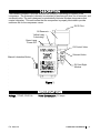
DESCRIPTION
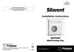
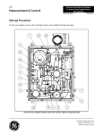
The Waukee Automatic Lubricator controls the amount of lubricating oil supplied to the
compressor. The Automatic Lubricator is comprised of an electronic timer, an oil reservoir, and
a solenoid valve. The unit is designed to automatically lubricate Waukee compressors that
require lubrication. This unit insures that the compressor is properly lubricated to provide
maximum life for the compressor vanes.
Oil Fill Port
Oil Reservoir
Yellow Lamp
“Lubricating”
Green Lamp
“Power ON”
Oil Control Valve
Solenoid Valve
Manual Lubrication Button
Oil Feed Sight
Window
Figure 1
SPECIFICATIONS
Voltage: 115VAC, 50/60 Hz
File: Manu016
Power Consumption: 0.2 amps
Carburetor User Manual
6
INSTALLATION
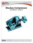
Mounting
If the Automatic Lubricator was purchased with a compressor it will already be mounted,
otherwise mounting will be required if the unit was purchased separately. The Automatic
Lubricator can be mounted onto the side of the compressor with the include mounting
bracket as shown in Figure 2 or anywhere within 2-3ft. of the compressor. The
Automatic Lubricator is a gravity feed type oiler, which requires the oiler to be mounted
higher than the compressor in order to function properly.
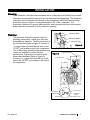
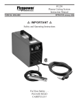
Plumbing
The Automatic Lubricator requires only two
plumbing connections, unless your oiler was
preinstalled by Waukee. The first connection is
the oil feed tube (Refer to Figure 2) Connect a
¼” copper tube from the solenoid valve to the
1/8”NPT port located on top of the compressor.
The oil feed tubing should be kept as short and
vertical as possible to provide the best
performance. The second connection is the
pressurized feedback (Refer to Figure 3)
Connect a ¼” copper tube from the top of the
oiler to the 1/8”NPT port located on the side of
the compressor.
Mounting Bolts
Mounting Bracket
¼” Oil Feed Tube
Figure 2
Figure 3
¼” Copper Tube
1/8” NPT Port
1/8” NPT Tee
1/8” Plug
File: Manu016
Compression Fitting
¼” Copper Tube
¼” Compression
Fitting
1/8” Isolation Valve
Carburetor User Manual
7
Wiring Guidelines
Your company may have guidelines for wiring installation. If so, you should check those
before you begin the installation. Here are some general things to consider:
Use the shortest wiring route whenever possible.
Route the wiring through an approved cable housing to minimize the risk of
accidental damage. Check local and national codes to choose the correct
method for your application.
CAUTION: To reduce the risk of electrical shock and also to prevent
damage to the Automatic Lubricator. It is advised to turn off the supply
power to the Automatic Lubricator before connecting or disconnecting any
wires.
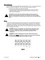
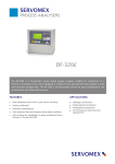
Wiring
The unit should be wired such that power is supplied to it only when the compressor is
running. It is very important that power to the Automatic Lubricator is “OFF” when the
compressor is not running. The recommended method for wiring the unit is to connect
power through the normally open contacts of the motor starter of the compressor’s drive
motor. See Figure 4 for wiring.
WARNING: If power is supplied to the unit while the compressor is off,
excessive oil may build up in the compressor causing damage to the
compressor and/or any components located downstream of the
compressor.
WARNING: The Unit is designed for use with 115VAC Single phase,
50/60Hz power ONLY!! Connection of any other power type may damage
the unit and may subject personnel to shock or injury.
Figure 4
File: Manu016
Carburetor User Manual
8
OPERATION
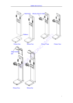
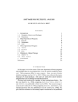
Filling the Oil Reservoir
Before opening the oil fill port, turn off the isolation valve on the
feedback line. (See Figure 3) Remove the Oil fill plug (See Figure
5) and fill the oil reservoir with Waukee Compressor Oil.
Part No’s COIL-1 (pint), COIL-2 (quart) or COIL-3 (gallon).
Once reservoir is full replace the oil fill plug and open the isolation
valve.
Figure 5
Oil Fill
Port
WARNING: Lack of or improper lubricating oil may
cause damage to the compressor.
Use Waukee Compressor Oil ONLY!!
CAUTION: Before removing oil fill plug turn isolation valve “OFF”. Failure
to turn isolation valve “OFF” will result in compressed gas leaking from
the oiler and may cause a hazardous situation. Gas leaking from oiler may
be flammable.
WARNING: Make sure isolation valve is open after filling oil reservoir with
oil and replacing the oil fill plug. If isolation valve is left closed oiler will
not be able to drop oil and cause premature failure of the vanes.
Starting the Compressor
Every time the compressor is started, the Green “Power On” light on the Automatic
Lubricator should be “ON” and remain on until the compressor is stopped. Also the
Amber “Lubricating” light will illuminate for 4 seconds. During this 4 second time, oil
should be seen dropping in the sight glass. The Automatic Lubricator is a ON-OFF cycle
timer, it will start with a 4sec “ON” time and after the “ON” cycle completes it will remain
“OFF” for a period of 1Hr. and will continue to cycle until power is removed.
Adjusting the Oil Flow Rate
The solenoid valve is factory set to provide the proper number of oil drops during the
“ON” period of 4 seconds. To verify or adjust the oil flow rate, depress and hold the
“Manual Lubrication Button” located on the left side of the Automatic Lubricator and
adjust the Oil Control Valve to obtain the proper number of oil drops within a 15 second
time interval. The number of drops required during the 15 second interval is displayed
on the nameplate attached to the front of the Automatic Lubricator’s enclosure. If the
nameplate is unreadable or the Automatic Lubricator will be used on a different
compressor that what it was ordered for, then refer to Table 1 on the following page to
determine the proper amount of drops for your compressor.
File: Manu016
Carburetor User Manual
9
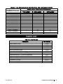
TABLE 1 – OIL RATE CHART IN DROPS OF OIL PER 15 SECOND PERIOD
Number of Drops Required over a 15 second period
Flow Output of Compressor
200CFH (5.6M3H)
400CFH (11.3M3H)
600CFH (17.0M3H)
750CFH (21.2M3H)
1000CFH (28.3M3H)
1250CFH (35.4M3H)
1500CFH (42.5M3H)
2000CFH (56.6M3H)
3000CFH (84.9M3H)
4000CFH (113.3M3H)
5000CFH (141.6M3H)
6000CFH (169.9M3H)
7000CFH (198.2M3H)
8000CFH (226.5M3H)
Output Pressure
1psig (6.9kPa)
3
3
3
4
4
4
4
6
6
6
7
7
7
7
Output Pressure
2psig (13.8kPa)
4
4
4
5
5
5
5
9
9
9
10
10
10
10
Output Pressure
3psig (20.7kPa)
5
5
5
6
6
6
6
10
10
10
12
12
12
12
PARTS LIST
TABLE 2 – PARTS LIST
Description
Amber Indicator Lamp
Green Indicator Lamp
Timer Board
Solenoid Valve Assembly
Manual Lubrication Button
Support Bracket for A, B, and C Compressors
Support Bracket for D, H, J, and E Compressors
Support Bracket for F, G, and N Compressors
Support Bracket for R, S, U, and W Compressors
Compressor Oil, pint
Compressor Oil, quart
Compressor Oil, gallon
File: Manu016
Part Number
1-2140
1-2139
1-2268
1-3119
1-3120
3-867
3-868
2-572
2-571
COIL-1
COIL-2
COIL-3
Carburetor User Manual
10
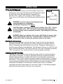
EXPRESS WARRANTY ON WAUKEE EQUIPMENT.
WAUKEE warrants its products for a period of one (1)
year from date of shipment from WAUKEE to the original
purchaser to be free from defects in material and
workmanship under normal recommended use, service,
inspection and maintenance. Normal recommended use,
service inspection and maintenance mean:
1. Not to be used in excess of nor below the rated
capacity, pressures and temperature ranges specified in
the applicable quotation, purchase order,
acknowledgment, marketing literature, nameplate(s),
specification sheet or the Installation, Operation,
Inspection and Maintenance Manual (THE MANUAL);
2. Using only clean liquids or gases (only liquids in liquid
Flo-Meters and only gases in gas Flo-Meters); air and fuel
gases used in mixing equipment to be clean and free of
solids all as further explained in THE MANUAL; and
3. Installation, operation, inspection and maintenance in
compliance with THE MANUAL; and
4. The WAUKEE products being used only in:
a. Ambient environments lower than 132° Fahrenheit (54°
Celsius) unless specifically designed and so labeled by
WAUKEE for higher temperatures; and
b. Non-corrosive environments; and
c. Completely protected from moisture, rain, snow or
other outside environments; and
d. Not to be used below 32° Fahrenheit (0° Celsius) unless
special precautions are taken for low temperature
conditions as shown in THE MANUAL.
5. Being used only for applications permitted by THE
MANUAL or other WAUKEE literature or special
applications approved in a separate written authorization
by WAUKEE.
WARRANTY EXCEPTIONS
This Warranty does not apply to damage caused by any or
all of the following circumstances or conditions:
system or other goods or services manufactured, sold or
provided by WAUKEE;
4. Misapplication, misuse and failure to follow THE
MANUAL or other literature, instructions or bulletins
(including drawings) published or distributed prior to
THE MANUAL.
The exclusive remedy under this Warranty or any other
express warranty is the repair or replacement without
charge for labor and materials of any WAUKEE parts
found upon examination by WAUKEE to have been
defective. Since certain WAUKEE equipment is heavy,
bulky and not deliverable by U.S. mail or other parcel
service, WAUKEE equipment may be returned only upon
written consent of WAUKEE and then only to the location
designated by WAUKEE. Generally such consent will be
given only upon the condition that the customer assume
and prepay all carrier charges and responsibility for
damage in transit.
Purchasers of WAUKEE products, equipment, goods or
services waive subrogation on all items covered under
their own or any other insurance.
DISCLAIMER
THIS WARRANTY IS EXCLUSIVE. WAUKEE
EXPRESSLY DISCLAIMS ANY AND ALL OTHER
WARRANTIES WHETHER EXPRESS OR IMPLIED
INCLUDING ANY IMPLIED WARRANTY OF
MERCHANTABILITY OR FITNESS FOR A PARTICULAR
PURPOSE OR ANY PURPOSE.
No person, including any dealer, seller or other
representative of WAUKEE is authorized to make, on
behalf of WAUKEE, any representations beyond those
contained in WAUKEE literature and documents or to
assume for WAUKEE any obligations or duties not
contained in this Warranty and Warranty Policy.
WAUKEE reserves the right to make design and other
changes, modifications or improvements to its products,
services, literature or systems, without any obligation, to
furnish or install same on any previously sold or delivered
products or systems.
1. Freight damage;
2. Parts, accessories, materials or components not
obtained from nor approved in writing by WAUKEE;
3. Any consequential or incidental damages including
but not limited to loss of use, loss of profits, loss of sales,
increased costs, arising from the use of any product,
File: Manu016
Carburetor User Manual
11
LIMITATION OF LIABILITY
It is expressly agreed that the liability of WAUKEE is
limited and WAUKEE does not function as an insurer.
The purchaser and/or user agree that WAUKEE is not
liable for loss, harm or damage due directly or indirectly
to any occurrence or consequences therefrom. If
WAUKEE should be found liable to anyone on any theory
(except any express warranty where the remedy is set
forth in Section 2 of this Warranty and Warranty Policy)
for loss, harm or damage, the liability of WAUKEE shall
be limited to the lesser of the actual loss, harm or damage
or the purchase price of the involved WAUKEE
equipment or service when sold (or when service
performed) by WAUKEE to its customer. This liability is
exclusive and regardless of cause or origin resulting
directly or indirectly to any person or property from:
2. The date and from whom you purchased your
WAUKEE equipment and your purchase order number.
3. State your difficulty, being sure to mention at least the
following:
4. Application.
5. Input pressure where Flo-Meters or compressors are
involved.
6. Condition of filters, strainers or screens, upstream or
downstream of the WAUKEE equipment.
7. Gas or liquid temperatures and other ambient
conditions at the time of the difficulty.
8. Type of lubrication being used (if any) - give specifics.
1. The performance or nonperformance of any obligations
set forth in this Warranty and Warranty Policy:
2 Any agreement including specifications between
WAUKEE and the customer;
9. Any other relevant pressures including gauge readings
both upstream and downstream of the WAUKEE
equipment.
10. All electrical information available.
3 Negligence, active, passive or otherwise of WAUKEE or
any of its agents or employees;
4. Breach of any judicially imposed warranty or
convenant of workmanship, durability or performance;
and
11. Performance activity.
12. Any other pertinent information. If a sketch would
help explain the difficulty, please include one.
WARRANTY FIELD SERVICE
5. Misrepresentation (under the Restatement, common
law or otherwise) and/or strict liability involvement.
6. Liability for fraud-in-the-inducement.
INFORMATION NECESSARY TO OBTAIN
TECHNICAL ASSISTANCE.
For WAUKEE to appropriately respond to a request for
assistance or evaluation of customer or user operating
difficulty. Please provide at a minimum the following
information:
If warranty Field Service at the request of the purchaser or
user is rendered and the difficulty is found not to be with
WAUKEE's product, the purchaser shall pay the time and
expense (at the prevailing rate at the time of the service) of
WAUKEE's field representative(s). Charges for service,
labor and other expenses that have been incurred by the
purchaser, its customer or agent without written approval
of WAUKEE will not be accepted. The OEM or other
reseller is responsible for transmitting installation and
operating instructions, THE MANUAL or other service
literature supplied by WAUKEE with the equip
1. Serial number and type or model of meter, compressor
or other equipment and all other data shown on the
nameplate and on the specific component which appears
to be involved in the difficulty;
File: Manu016
Carburetor User Manual
12
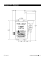
APPENDIX “A” - DRAWINGS
File: Manu016
Carburetor User Manual
13
Reach us at www.group-upc.com
United Process Controls brings together leading
brands to the heat treating industry including
Waukee Engineering, Furnace Control, Marathon
Monitors and Process-Electronic.
We provide prime control solutions through our
worldwide sales and services network with easy-toaccess local support.
WAUKEE ENGINEERING COMPANY, INC.
A member of United Process Controls
5600 West Florist Avenue, Milwaukee, WI 53218, U.S.A.
Phone: +1-414-462-8200 Fax: +1-414-462-7022
e-mail: [email protected]
File: Manu016
Carburetor User Manual
14