1
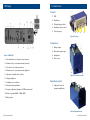
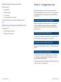
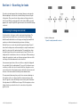
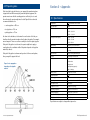
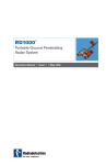
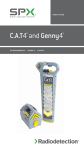
RD545 Acoustic leak detector Operation Manual l Issue 2 l June 2009 90/RD545-OPMAN-ENG/02 Preface Before you begin Thank you for your interest in Radiodetection’s RD545 water leak detection and location system. Please read this user manual before attempting to use the RD545 system. Radiodetection products, including this manual, are under continuous development. The information contained within is accurate at time of publication; however the RD545, this manual and all its contents are subject to change. Radiodetection Limited reserves the right to modify the product without notice and some product changes may have taken place after this user manual was published. Contact your local Radiodetection dealer or visit www.radiodetection.com for the latest information about the RD545 product family, including this manual. Important notices General This instrument, or family of instruments, will not be permanently damaged by reasonable electrostatic discharge and has been tested in accordance with IEC 801-2. However, in extreme cases temporary malfunction may occur. If this happens, switch off, wait and switch on again. If the instrument still malfunctions, disconnect the batteries for a few seconds. Safety This equipment should be used by fully qualified and trained personnel only. Reduce audio level before using headphones to avoid damaging your hearing. WARNING! This equipment is NOT approved for use in areas where hazardous gases may be present. ii RD545 Operation Manual RD545 Operation Manual iii Training Radiodetection provides training services for most Radiodetection products. Our qualified instructors will train equipment operators or other personnel at your preferred location or at Radiodetection headquarters. For more information go to www.radiodetection.com or contact your local Radiodetection representative. Trademarks RD545 is a trademark of Radiodetection Ltd. Copyright statement Copyright 2009 Radiodetection Ltd - SPX Corporation. All rights reserved. Radiodetection is a subsidiary of SPX Corporation. SPX and Radiodetection are trademarks of Radiodetection Ltd. and SPX Corporation. Due to a policy of continued development, we reserve the right to alter or amend any published specification without notice. This document is protected by copyright and may not be copied, reproduced, transmitted, modified or used, in whole or in part, without the prior written consent of Radiodetection Ltd. Table of contents Preface iii Before you begin iii Important notices iii General iii Safety iii Training iv Trademarks iv Copyright statement iv Section 1 – Description 1 1.1 General information 1 1.2 System components 1 1.3 Display 2 1.4 Central unit 3 Section 2 – Operation 4 2.1 Charging the batteries 4 2.2 Switch on RD545 4 2.3 Battery control 4 2.4 Level display and data memory 4 2.5 Microphone connection 5 2.5.1 Testrod 5 2.5.2 Ground microphone 5 2.6 Adjustments 2.6.1 Headphone volume 5 2.6.2 Adjusting the level display 5 2.7 Selecting operation mode 6 2.7.1 Operation modes 6 2.8 Input settings iv RD545 Operation Manual 5 6 2.8.1 Settings overview 6 2.8.2 Settings 7 RD545 Operation Manual Section 3 – Leakage-borne noise 9 3.1 Noise transmission through the pipeline 9 3.2 Noise transmission through the soil 9 3.3 Above-ground noise pick-up method 9 3.4 Noise pick-up at the outside of the pipeline 9 Section 4 – Searching for leaks 10 4.1 Locating the leakage area (testrod) 10 4.2 Pinpointing leaks 12 Section 5 – Appendix 5.1 Specifications 13 13 Section 1 – Introduction 1.1 General information The RD545 leakage detection system combines decades of experience and state-of-the-art sensor technique with the latest electronic technology. The RD545 allows an untrained operator to locate leakages with ease. Leakageborne noises are amplified and interfering noises are filtered out. A major advantage of the RD545 is that it offers an automatic saving of measurement data to memory. In summary the RD545 features: • Ease of operation. • Leakage noise amplification. • Advanced filtering. • Rapid on-screen leak detection. • Automatic backlit LCD. 1.2 System components 1 unit RD545 central unit 1 unit testrod 1 unit leveling base 1 unit charger 1 unit headphones 1 unit ground microphone including cable 1 unit operator´s manual vi RD545 Operation Manual RD545 Operation Manual 1.3 Display 1.4 Central unit Controls: 1 1. LCD. 2. Start button. 3. Setting display sensitivity. 4. Headphone volume control. 5. Select frequency. 2 3 4 5 Figure 2: Controls. Connections: 1. Battery charger. 2. Ground microphone input. Figure 1: RD545 LCD 1. Saved minimum levels of previous measurements. 3. Headphones. 4. Photo sensor. 2. Minimum level of current measurement (numerical). 3. Present level of current measurement. 4. Minimum level of current measurement (graphical). 5. Adjustment of amplification sensitivity. Figure 3: Connection sockets. 6. Display headphones. 7. Headphone noise reduction. 8. Automatic display modulation. 9. Frequency adjustment (geophone / PWG measurement). Adjustment control: 1. Adjustment control for automatic amplification. 10. Mode of operation (GEO – PWG – GTX). 11. Battery status. Figure 4: Adjustment knob. RD545 Operation Manual RD545 Operation Manual 2.5 Microphone connection Section 2 – Operation The input socket (2) for the ground microphone and the testrod is located on the side of the device. 2.1 Charging the batteries 2.5.1 Testrod Connect the battery charger to the power supply (220 volt) and to socket 6 of the RD545. The testrod is used to listen to directly accessible contact points such as hydrants and valves to pinpoint the location of the pipe fracture. The charging status is displayed while the battery is being charged. Charging is completed when the display reads O.K. Internal software prevents the batteries from being damaged or overcharged. 2.5.2 Ground microphone 2.2 Switch on RD545 RD545 can be switched on either by pressing Start (2) on the central unit or by initiating a measurement via the handle of the connected sensor. 2.3 Battery control The LCD displays the current voltage and reminds the user to charge the device, when necessary. 2.4 Level display and data memory Measurement 1 Measurement 2 Measurement 3 Measurement 4 2.6 Adjustments 2.6.1 Headphone volume You can adjust the headphone volume to suit your preferences by using the adjusting knob (4) or the receiver earpiece. The headphone volume is automatically reduced for hearing shock protection purposes when the leak noise is too loud (symbol (7) hammer displayed). 2.6.2 Adjusting the level display Measurement 5 When the activation key on the handle of the sensor or the central unit is released, the system will save the current minimum value. The display shows the last 5 levels and the current level simultaneously. RD545 Operation Manual The broadband-type ground microphone (70 – 800 Hz) can locate all leak noise. It is used above ground and is suitable for use with soil types. The signal received by the ground microphone is displayed on the LCD (2) as a 2 digit number in the range of 00 – 99. The signal’s noise is also played through the headphones. You can adjust the position of the display using the amplification control (5) so that the displayed noise level is in the middle of the screen; this allows the user to view all possible peaks and troughs. NOTE: Changing the position of the amplification control will overwrite displayed data. RD545 Operation Manual 2.7 Selecting operation mode Hearing shock protection for PWG measurement Pressing the adjustment control will allow the user to access the operation mode selection field. The display will show the selected mode as a flashing icon. Press the adjustment control key again to change the operation mode. Unlike regular geophone measurement procedures, the clearest noise is received by a PWG measurement. Therefore, the shock protection should be switched off. 2.7.1 Operation modes NOTE: The RD545 has to be switched off before setting the parameters / displaying the device parameters. • GEO: Geophone or testrod measurement procedure. • PWG: Search pipelines with the ground pick-up (pipeline to be irradiated acoustically by Pulse Wave Generator). • GTX: Search empty pipelines (pipeline to be irradiated through loudspeakers). 2.8 Input settings Input parameters: switch-off time general setting for hearing shock protection hearing shock protection for PWG measurement display – serial number Procedure: 1. Plug in power supply unit 2. When is displayed, press the adjust key and the switch-on key simultaneously. The display will read OK and display a two-digit number representing a menu choice. By pressing the power key, the selected option will be initiated. • 01Switch-off time. • 00Pressing the adjust key cancels the menu. • 05Version number. • 04Serial number. • 03Set hearing shock protection for PWG. 2.8.1 Settings overview • 02General setting for hearing shock protection. Switch-off time 2.8.2 Settings Period of time between the last geophone operation and the automatic switchoff of the RD545. Press the adjustment control key to activate the menu for changes. A tick () will be displayed, and the changes will be implemented. The start key selects the specific option. General settings for hearing shock protection Strong short-term noises such as water hammer can potentially damage the user’s hearing. To reduce risk the RD545 geophone features hearing shock protection. In the event of water hammer or other pipeline noised, the RD545 will automatically reduce amplification to help prevent damage to hearing. The user can adjust the sensitivity of the hearing shock protection to suit their preferences. NOTE: The device must be switched off before setting the parameters. RD545 Operation Manual 01 Set the switch-off time Calculation of the switch-off time as follows: The set figure is 2. Example: 20 sec. + 20 sec. X 2 = 60 sec. Press the adjust key again to accept the setting. The display now shows a tick (v). RD545 Operation Manual 02 General setting for hearing shock protection Section 3 – Leakage-borne noise The figures represent: • 1 High sensitivity. • 2 Medium sensitivity. • 3 Low sensitivity. • 0 Hearing shock protection de-activated. Press the adjust key again to accept the setting. The display now shows a tick (). 03 Setting hearing shock protection for PWG measurement The figures represent: Every pressurized pipeline system creates leak noise at a fracture point. Different sizes and dimensions of pipeline cracks or fractures result in different noise volumes and frequencies. There are two ways of using the RD545 to detect leak noise.. 3.1 Noise transmission through the pipeline Fittings such as hydrants, valves and other metallic connections can transmit leak noise. Normally, fractures on plastic pipelines are accompanied by low frequency leak noise, and fractures on metallic pipelines generate high frequency leak noise. • 1 (2,3): Shock protection activated. • 0: Shock protection de-activated. 3.2 Noise transmission through the soil The soil around the leakage spot is activated due to the energy of the leaking fluid. The vibrations can be acoustically detected on the surface. 3.3 Above-surface noise pick-up method Experience has shown that frequencies between 70 - 800 Hz are indicators of leak noise. 3.4 Noise detection at metallic fittings The testrod point detects leak noise at a fitting (water meter, valve, hydrant, etc.). Depending on the pipeline material (for example plastic or metal), the frequencies picked up differ significantly. Therefore the frequency band for this method is wider than the frequency band for the above-surface noise pick-up method. RD545 Operation Manual RD545 Operation Manual Section 4 – Searching for leaks You need a systematic approach when locating a leakage in a water pipeline. Before attempting to locate the leak, it’s advised that you first trace the path of the pipeline. Then you must locate the general area of the pipe where the leak is located. Finally you must pinpoint the leak’s location. With a systematic approach, the complete length of the pipeline must be checked until the leakage is detected. 4.1 Locating the leakage area (testrod) Use the testrod to check any accessible contact points along the pipe. The operator must ensure that the noises received are the result of a leakage (muffled sound) rather than the result of stopper neckings (high sound). Both sounds are useful when determining the general area of a leakage. Leckort = leakage spot Figure 5: Locating leaks with the testrod Note that flow noises can also be generated by regular discharges. Figure 5 shows how the leakage area can be narrowed by accessing the measurement data of the contact spot of the particular pipeline. The example below shows the highest figures between the measurement points 3 and 4. Therefore, the leakage must be located between these two contact spots. When narrowing a leakage, the operator has to make sure that no measurement data exceeds the scale range so that the maximum value can be identified. If a measurement point shows a full-scale reflection, re-adjust the display with the control knob (3) or the adjusting knob (1) e.g. up to 50 so that an increase in reflection is visible. In the case of a reduced reflection, the pipeline section concerned has to be checked again in order to identify the actual increase and decrease of the volume and thus to identify the two maximum values. The measurement data memory has proved to be an enormous advantage as the last data is at the user´s disposal until the next measurement procedure starts. The pipeline section with the highest noise intensity can be determined if the adjustments of the RD545 are not changed. The following above-surface leakage detection procedure then has to be carried out on the particular pipeline section. 10 RD545 Operation Manual RD545 Operation Manual 11 4.2 Pinpointing leaks If the testrod has located a leak noise, you can apply the ground microphone to pinpoint the leak. When moving the ground microphone equipment, the operator must ensure that the sounding points are sufficiently close to each other otherwise the operator might miss the leak. Figure 6 below shows the recommended distances for: • cast iron pipelines = 250 cm • steel pipelines = 150 cm Section 5 – Appendix 5.1 Specifications Amplification: ≥ 60,000fold with low noise factor Input impedance: 1 MΩ Filter (testrod): 70 Hz – 4,000 Hz 250 Hz – 2,000 Hz • plastic pipelines = 75 cm 250 Hz – 1,000 Hz As shown in the chart above, to determine the exact location of the leak you should position the ground microphone directly above the pipeline. For example, an error margin of 1m can occur when searching for a leak on a plastic pipeline. If the path of the pipeline is not known, the operator might have to apply a search pattern; the coordination width of this pattern depends on the pipeline material (see above). Filter (ground microphone): If the path of the pipeline is unknown and you do not follow a search pattern, then you may fail to pinpoint the leak. Adjust function: display sensitivity automatically set Display: automatically illuminated LCD Displayed data: current value 200 Hz – 800 Hz 100 Hz – 500 Hz 70 Hz – 250 Hz Data memory: automatic (last 6 measurements) Functions: detecting pipeline fractures locating pipelines (receiver) minimum value Figure 6: noise propagation depending on the pipeline material averaged value remaining battery capacity state of charging Battery control: through microcontroller Output impedance: < 10 Ù Power supply: 7.2 volt Operating time: about 20 hrs. under normal conditions Microphone socket: bayonet type Headphones socket: 6.3mm (mono) jack type Operating temperature: between -15°C and +55°C Storing temperature: between –25°C and +65°C Dimensions L/W/H (central unit): 210 / 120 / 105mm Weight (central unit): about 1,700 gram Specifications are subject to change without prior notice. 12 RD545 Operation Manual RD545 Operation Manual 13 America Radiodetection 154 Portland Road, Bridgton, ME 04009, USA Tel: +1 (207) 647 9495 Toll Free: +1 (877) 247 3797 Fax: +1 (207) 647 9496 Email: [email protected] Web: www.radiodetection.com Pearpoint 72055 Corporate Way, Thousand Palms CA 92276, USA Tel: +1 800 688 8094 Tel: +1 760 343 7350 Fax: +1 760 343 7351 Email: [email protected] Web: www.radiodetection.com Radiodetection (Canada) 344 Edgeley Boulevard, Unit 34, Concord, Ontario L4K 4B7, Canada Tel: +1 (905) 660 9995 Toll Free: +1 (800) 665 7953 Fax: +1 (905) 660 9579 Email: [email protected] Web: www.radiodetection.com Europe Radiodetection Ltd (UK) Western Drive, Bristol BS14 0AF, UK Tel: +44 (0) 117 976 7776 Fax: +44 (0) 117 976 7775 Email: [email protected] Web: www.radiodetection.com Radiodetection (France) 13 Grande Rue, 76220, Neuf Marché, France Tel: +33 (0) 2 32 89 93 60 Fax: +33 (0) 2 35 90 95 58 Email: [email protected] Web: http://fr.radiodetection.com Radiodetection (Benelux) Industriestraat 11, 7041 GD ’s-Heerenberg, Netherlands Tel: +31 (0) 314 66 47 00 Fax: +31 (0) 314 66 41 30 Email: [email protected] Web: http://nl.radiodetection.com Radiodetection (Germany) Groendahlscher Weg 118, 46446 Emmerich am Rhein, Germany Tel: +49 (0) 28 51 92 37 20 Fax: +49 (0) 28 51 92 37 520 Email: [email protected] Web: http://de.radiodetection.com Asia-Pacific Radiodetection (Asia-Pacific) Room 708, CC Wu Building, 302-308 Hennessy Road, Wan Chai, Hong Kong SAR, China Tel: +852 2110 8160 Fax: +852 2110 9681 Email: [email protected] Web: www.radiodetection.com Radiodetection (China) Hongfu Mansion, Room 61622, Zheng Ge Zhuang, Bei Qi Jia Town, Chang Ping District Beijing 102209, China Tel: +86 (0) 10 8975 5540 Fax: +86 (0) 10 8975 5640 Email: [email protected] Web: http://cn.radiodetection.com Radiodetection (Australia) Unit 14, 5-7 Prosperity Parade, Warriewood NSW 2102, Australia Tel: +61 (0) 2 9979 8555 Fax: +61 (0) 2 9979 7733 Email: [email protected] Web: www.radiodetection.com www.radiodetection.com Radiodetection products are under continuous development and are subject to change, we reserve the right to alter or amend any published specification without notice. Copyright 2009 Radiodetection Ltd. - SPX Corporation. All rights reserved. Radiodetection Ltd. is a subsidiary of SPX Corporation.