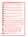
1
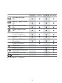
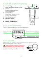
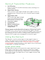
U se r G ui d e C.A.T4™ and Genny4™ 90/ UG092E NG /03 ISSUE 3 03/2012 ALWAYS DIG WITH CAUTION Risk of property damage, death, or serious injury may result if buried pipes, and cables are not properly located before digging. Read and follow all instructions and warnings in the owner’s guide before using the C.A.T4 and Genny4. Regularly check your C.A.T4 and Genny4, in all modes, over a cable which gives a response you are familiar with. Some power cables DO NOT radiate detectable power signals. Power and Radio signals may not be present. It is advisable to use the Genny4 whenever searching for pipes and cables. Do not use the C.A.T4+/eC.A.T4+ depth estimation function to decide if mechanical digging over a buried conductor is appropriate. StrikeAlert ™ may not activate even if a live power cable is present. The presence of ‘StrikeAlert Activated’ or ‘CALSafe Enabled’ labels do not guarantee that the relevant feature is activated. Keep mobile phones away from cable and pipe locators when in operation. Minimum distance 60cm/24" recommended. The C.A.T4 cannot indicate whether a signal comes from a single conductor or from several cables or pipes bundled or buried in close proximity to each other. Call your local support number (available from: www.radiodetection.com) for questions regarding the proper use, maintenance, and repair of the C.A.T4 and Genny4. It is recommended that the C.A.T4 and Genny4 are serviced at least once a year and have their calibration validated using Radiodetection approved test equipment. Radiodetection will accept no responsibility for repairs carried out by unauthorized repairers. Even if using a C.A.T4 and Genny4, ALWAYS DIG WITH CAUTION. 2 C.A.T4C.A.T4+ eC.A.T4 eC.A.T4+ Avoidance Mode™ (A) Genny™ signal locate (G) Power signal locate (P) Radio signal locate (R) Small Diameter Locate frequency eCert Dynamic Overload Protection ™ Depth Estimation StrikeAlert ™ Data acquisition Service due indicator SWING warning CALSafe ™ ™ Standard Option 3 C.A.T4 Locator Features 1 2 3 1. On/Off Trigger. Press and hold to use the C.A.T4. 4 5 2. LCD Screen. Displays signal level and status information. 3. Loudspeaker. Detachable speaker for use in noisy environments. 4. Sensitivity Control. 6 5. Function Switch. Selects locate mode. 6. Battery compartment. C.A.T4 s cr e e n featu r e s The C.A.T4 screen displays the following features: Mode /StrikeAlert /Swing indicator Depth / Warning readout Signal Strength bargraph Depth estimation button C.A.T4 S peak e r When using the C.A.T4 in noisy environments, the speaker can be detached and held closer to the ear. To avoid excessive noise exposure, hold the speaker no closer than 15cm (6") from the ear. Prolonged use in this position should be avoided. 4 91dB(A) 15cm Genny4 Transmitter Features 1. On/Off button. Press to switch On and Off. Hold down when switching on to reduce volume. 2. Signal Boost Button. Press to boost locate signal strength; press again to return to standard power. Genny4 starts-up in standard signal strength mode. 3. Signal Boost LED. 3 LED lit when high signal strength power level selected. Flashing LED indicates low battery level. 4. Accessory socket. 2 5. Loudspeaker. 4 6. Battery compartment. 7 6 5 1 7. Accessory storage compartment. Genny4 signals can be detected by all previous 33 kHz C.A.T models including C.A.T3. C.A.T4 will also locate Genny3 signals. Genny4 provides a second locate signal alongside the 33kHz signal which can be located by C.A.T4 to assist in locating smaller cables and spurs. Previous C.A.T models are not designed to locate this signal. Using the Genny4 The Genny4 is used to actively apply a locate signal to pipes or cables. This signal can be traced using the C.A.T4 locator in either Avoidance Mode or Genny mode. Use of the Genny is strongly recommended, as passive power or radio signals may not be present, or detectable, on all pipes and cables. S I G NAL B oost M od e The Signal Boost button will increase the output signal level to give better signal on the pipe or cable, and may increase the useable locate distance from the Genny4. In Signal Boost mode the Signal Boost LED will light. The Signal Boost switch toggles between high and normal output. 5 Locati n g Small Diam ete r Cable s C.A.T4 and Genny4 have been designed to increase the likelihood of detecting smaller cables such as telephone lines or CATV, particularly service drops from the road or pathway to a property. The Small Diameter Locate frequency transmitted from the Genny4 is designed to ‘jump’ onto these cables using one of three methods: Signal jumping through external insulation /coatings With the Genny4 switched off, plug the direct connection leads into the Genny4 and connect the black lead to the earth stake or suitable ground point. Clip the red lead directly onto the cable insulation to allow the Small Diameter Locate signal to jump onto the metallic wires inside. If clipping on is not possible, place the red clip as near to the cable as possible, which may include clipping to the protective cover of the service. Alternatively, run the red lead around a non-metallic casing or conduit containing the target utilities, and clip it to itself to achieve this effect. Switch on the Genny4 and set the C.A.T4 to Genny mode to locate the buried cable. Note that the signal boost function will not have a significant effect in this mode. Signal jumping from an accessible cable If a small diameter cable runs close to, or parallel to, a more accessible cable – e.g. a street lighting cable, the Small Diameter Locate signal may be able to jump from one cable to another. Use the Direct Connection or Signal Clamping methods as described below to transmit both signals to the accessible cable. When scanning an area 6 for underground utilities, the jumping Small Diameter Locate frequency can be differentiated from the standard Genny signal by a different audio tone. Di r e ct Con n e cti on Connection to a power cable sheath should only be undertaken by qualified personnel. Direct Connection is an effective way to apply the Genny4 locate signal to a specific cable or pipe network so that it can be traced from above ground. Connections can be made to any metallic part of the pipe or cable such as valves, meters, junction boxes, street lights, pipeline markers or other access points. With the Genny4 switched off, plug the Direct Connect lead into the accessory socket. Attach the red lead to the pipe or cable (if necessary, clean the connection point to ensure a good electrical contact). If the jaws of the clip do not open far enough, and if the connection point is a suitable material, use the supplied magnet. Connect the black lead to the earth stake which should be secured in the ground 3 – 4m away from, and at right angles to the target line. Alternatively the black lead may be clipped to a valve box, manhole cover or another earthed point. Use the earth spool lead to extend the earth connection if necessary. Switch the Genny4 on. A good connection is indicated by a drop in loudspeaker tone. If there is no tone, or if the power boost LED flashes, replace the batteries. Use the C.A.T4 to scan the area for the target pipes or cables (see ‘Locating with C.A.T4’). 7 Sig nal Clam pi n g The optional Signal Clamps can be used to apply the Genny4 locate signal safely to a pipe or cable up to 215mm in diameter without interrupting the supply. Signal clamps are not suitable for connecting around lamp posts. Plug the Clamp into the Genny4 accessory socket. Place the Clamp around the pipe or cable ensuring the jaws are completely closed. Switch the Genny4 on then open and close the Clamp. If the jaws are closing correctly there will be a change in tone as the jaws are closed. An earth connection from the Genny4 is not necessary but optimal signal transfer is only generally achieved if the target line is grounded at both ends. This is usually the case with power cables. Use the C.A.T4 to scan the area for the target pipes or cables (see ‘Locating with C.A.T4’). Sig nal I n d u cti on Induction is a convenient and quick way of applying the Genny4 locate signal to a pipe or cable where limited access does not permit the use of Direct Connection or Signal Clamping. Place the Genny4 over the assumed position of the conductor and in-line with its assumed direction. Move at least 10m away and use the C.A.T to scan for pipes and cables (see ‘Locating with C.A.T4’). Working too close to the Genny4 may give false readings as the C.A.T4 will detect airborne signals directly from the Genny4 rather than the target line. For best results, repeat the scan with the Genny facing at 90˚ to the first scan position. 8 Locating with C.A.T4 C.A.T an d G e n ny Fu n cti onal te st Regularly check your C.A.T4 and Genny4, in all modes, over a cable which gives a response you are familiar with. • Place the Genny on the ground, switch on and check for an audible sound. If no sound is heard or the low battery warning light is flashing, replace the batteries before use. • Switch on the C.A.T by squeezing the trigger, checking for an initial ‘chirp.’ A low tone indicates low batteries. If no sound is heard, replace the batteries before use. • Rotate the C.A.T function switch and check that the appropriate letter is displayed in each position of the switch. • Set the C.A.T to Genny mode at maximum sensitivity, hold at waist height pointing toward the Genny with the flattest part of the housing parallel to the ground and check that the C.A.T can detect the Genny up to 15m away with a clearly audible sound. Ope rati n g th e C.A.T Grip the handle. Press and hold the trigger and listen for the bleep indicating the batteries are OK. Replace both batteries if there is no bleep or if the battery icon is flashing. eC.A.T4 and eC.A.T4+ only When a service /calibration is due in 31 days or less, the screen will display ‘CAL’ at startup, followed by the number of days until a service /calibration is due. CALSafe™ CALSafe™ enabled units are equipped with a system which does not permit them to function once they are beyond the expected service/calibration date. If flashes continually on startup, immediately return your C.A.T for service /calibration. Do not attempt to use a C.A.T4 for tracing pipes or cables outside its calibration period. If in doubt, contact the person responsible, or Radiodetection. 9 Select Mode C.A.T4 models are equipped with four locate modes: Avoidance Mode (A): detects all locate signals simultaneously, including Genny, Power and Radio signals. The sensitivity control adjusts the Power, Radio and Genny signal levels simultaneously. Genny Mode (G): detects the locate signals produced by a Genny. There are various ways of applying the Genny signal (see ‘Using the Genny4’). Using a Genny is the most reliable way to detect a pipe or cable. The C.A.T4 and Genny4 feature new locate signals that make the combination more sensitive to small core cables (e.g. telecoms & street lighting). Power Mode (P): detects signals originating from power transmission networks. These signals may be found on any pipe or cable, not just power cables. Some power cables DO NOT radiate detectable power signals. Power signals may not be found on power cables that are switched off (e.g. a street light cable during daylight hours). Always use a Genny before excavating. Radio Mode (R): detects radio signals originating from distant radio transmitters as they travel along underground pipes and cables. Radio signals are not always present. Always use a Genny before excavating. U s i n g th e C.A.T4 Hold the C.A.T4 with the blade vertical and with the lower edge just above the ground. Do not swing the C.A.T4 or tilt it more than a few degrees from the vertical. Swinging the C.A.T will affect locate accuracy; eC.A.T4 and eC.A.T4+ models feature SWING, a sensing device to remind operators to use the C.A.T correctly. Locating cables and pipes The sensitivity control is used to narrow the field in which the C.A.T4 can locate a pipe or cable. The sensitivity control should be set to maximum before beginning to locate. 10 In all locate modes the bargraph and sound levels increase as the C.A.T gets closer to a pipe or cable, and reduce once it passes beyond it or as it gets further away. As the bargraph readout passes maximum over a pipe or cable, turn the sensitivity control down and move back over the locate position. By repeating this process back and forth across the maximum readout position, the cable or pipe’s position can be pinpointed. The tidemark feature hold the maximum bargraph reading to ease identification of a peak readout. If the position cannot be easily determined using Avoidance Mode, switch between the dedicated locate modes (Genny, Power or Radio) before adjusting the sensitivity control to pinpoint the cable or pipe. Determining a cable or pipe’s direction Once a cable or pipe’s position has been pinpointed, rotate the C.A.T4 above it. The C.A.T is at right angles across the cable or pipe when the bargraph and audio are at a maximum, and is directly inline with it when the bargraph and audio are at a minimum. Check for accuracy by varying the sensitivity control while rotating the C.A.T. (This process can be less precise in Power Mode because of the nature of detectable power signals). Trace the buried conductor keeping the C.A.T4 vertical and moving it steadily from side to side. Follow the line of the buried conductor, marking it as required across the area to be excavated. 11 Scanning an area before digging An initial sweep using Avoidance Mode is recommended, followed by detailed scans using the other modes. Use the Genny mode for Depth estimation once a pipe or cable has been detected (C.A.T4+ and eC.A.T4+ only). Turn the Function Switch to (Avoidance Mode) to sweep the area for cables or pipes radiating Genny, Power or Radio signals. Turn the sensitivity control to maximum before starting. If the signal bargraph does not move from maximum, reduce the sensitivity control so that the bargraph is below half-way before starting. Sweep the area to be excavated with a steady and deliberate motion. Begin by walking the perimeter of the proposed excavation site. Then walk the length of the of the excavation site, moving across the width in parallel sweeps around 0.5 metres apart. If using a Genny in induction mode, position the Genny as shown so that the chevrons on the C.A.T4 are inline with the chevrons of the Genny4. Then sweep across the width of the excavation site, moving up the length. If using a Genny in induction mode, position the Genny as shown. If a cable or pipe is located, first establish the direction of the cable or pipe, then trace it across the area to be excavated, marking if required. Then resume sweeping over the excavation site. 0.5 metres 0.5 metres Minimum 10 metres Minimum 10 metres 12 Active search using Induction – finding parallel pipes and cables Placing the Genny4 on its side swamps an area with Genny signal. Note that signal is not transmitted directly below the Genny4 in this orientation, so repeat the exercise with the Genny4 moved to the side by at least 1m. Alternatively, use a two man technique to search an area for buried utilities as shown. 13 Eliminating adjacent cables or pipes (‘Nulling out’) In some applications a cable or pipe carrying a signal can mask adjacent utilities. For example, a large locate signal could be flowing along a large cable that is running close to a second cable with a smaller signal. In this situation C.A.T4 can be expected to locate the signal from the larger cable but may not locate the second cable. To locate the second cable carry out the following: 1. Using the Genny4 in induction mode, place the Genny4 on its side directly over the large cable, and in-line with its direction as illustrated. 2. The cable beneath the Genny4 should now have no locate signal transmitted to it, but other cables in the vicinity should have the Genny signal transmitted to them and may now be located with the C.A.T4. Estimating line depth using the C.A.T4+/eC.A.T4+ and Genny4 Do not use the C.A.T4+ or eC.A.T4+ depth estimation function to decide if mechanical digging is appropriate. Depth estimations are only possible when using the C.A.T4+ or eC.A.T4+ in Genny mode. If using the Genny4 in induction mode, ensure that the depth estimation position is at least 10m from the Genny. If using direct connection or a signal clamp, this distance can be reduced to approximately 5m. Once a cable or pipe has been located, position the C.A.T Minimum 10 metres recommended above its position and at right angles to its direction. Press and release the depth button. The display will show the estimated depth to the detected conductor. Do not estimate depth near a bend or tee in a cable or pipe. 14 Dynamic Ove r load Pr ote cti on All C.A.T4 models incorporate Dynamic Overload Protection, a powerful signal processing tool that identifies and automatically rejects electrical interference that may otherwise overload the C.A.T’s electronics. Dynamic Overload Protection allows the operator to locate pipes and cables in electrically noisy environments such as near power sub stations or near overhead high-voltage cables. Note that Dynamic Overload Protection will not overcome very high levels of interference. In this situation the Signal Overload Warning will appear (see below). War n i n g s Signal Overload If the C.A.T4 is used in areas where very large power signals are present, the signal bargraph will flash. In this condition the sensitivity control and depth function will not operate and you are advised to try lifting the C.A.T4 to bring it out of the overloaded condition or use the C.A.T4 in a different location. When taking depth readings Conductor out of range. Selected mode does not support depth estimations Not possible to indicate depth eg, high levels of electrical interference. StrikeAlert™ The optional StrikeAlert feature warns the operator of shallow pipes and cables. To check if your C.A.T4 has StrikeAlert, look for the StrikeAlert Activation sticker on the side of the C.A.T4. When a shallow cable or pipe is detected in Power, Genny or Avoidance Mode, StrikeAlert flashes an asterix and sounds a distinctive warbling audio tone. StrikeAlert is not activated when tracing Radio signals. eC.A.T4 and eC.A.T4+only Warns that a C.A.T is being used too far from the vertical or moved too quickly for reliable cable or pipe location. On startup, warns that the C.A.T is due for service in less than 30 days, followed by number of days until service is due. If C.A.T is CALSafe™ enabled, the unit is past its calibration due date. Return for immediate service. eC.A.T4 and eC.A.T4+ will log warnings when displayed. 15 Deactivating warnings If required, for example if it is necessary to locate at an angle, the StrikeAlert and SWING warnings can be temporarily disabled by pressing and holding the depth button for the duration of the battery test bleep at switch on. eC.A.T4 models will log this action. Optional Accessories M ou s e Sig nal Tran s mitte r – f or n on m etallic utiliti e s The Mouse is a small self-contained watertight signal transmitter which can be located by the C.A.T4 in Genny mode or Avoidance Mode. Unscrew the housing and insert batteries in the orientation shown by the diagram in the battery compartment. To check for correct operation, place the Mouse on the ground, set the C.A.T4 to Genny mode and, whilst holding the C.A.T4 in line with the Mouse, check that the signal is being received. Insert the Mouse into the duct or drain and adjust the C.A.T4 sensitivity to receive the signal. Smaller ghost signals appear before and behind the main signal position. Locate all three peaks to be sure the largest middle one is identified as the Mouse position. Rotating the C.A.T4 about its axis to obtain the largest signal puts the C.A.T4 in line with the Mouse and is a good way of identifying the direction of the duct or pipe. 16 Estimating Mouse depth using the C.A.T4+ Do not use the C.A.T4+ or eC.A.T4+ depth estimation to decide if mechanical digging is appropriate. Depth estimations are only possible when using the C.A.T4+ or eC.A.T4+ in Genny mode. Locate the main Mouse signal as previously described. Hold the C.A.T4 vertical and in line with the Mouse. Press and hold the depth button until ‘M’ appears on the display and then release. The depth estimation will be displayed. Note: If the StrikeAlert feature is enabled the alarm will activate at approximately 1.2m when locating a mouse. If this is inconvenient, the StrikeAlert feature can be disabled in the Genny mode by pressing and holding the depth button for the duration of the battery test bleep at switch on. Fle x iTrace ™ – to locate n on-m etallic utiliti e s FlexiTrace™ is a 50m (165') flexible conductive rod with a built-in mouse that can be inserted into non-metallic pipes and ducts to allow them to be located at depths of up to 3m (10') FlexiTrace can be inserted into a pipe or duct as small as 12mm (½") internal diameter, and with bends as tight as 250mm. To use as a mouse, connect both transmitter leads to the FlexiTrace lugs. In this mode, only the tip of the FlexiTrace will be locatable. To trace the whole length, connect the red transmitter lead to a FlexiTrace terminal and ground the black lead, either to the earth stake or to an appropriate earthing point. Live Plu g Con n e ctor Do not use the supplied Direct Connect leads to connect to live cables. Use the Radiodetection Genny Live Plug Connector or Live Cable Connector. Failure to do so may result in injury or equipment damage. Connection to live power cables should only be undertaken by qualified personnel. 17 The Live Plug Connector applies the Genny signal to a live domestic power socket and, via the domestic wiring system, to the service and supply cable in the street. Connect the Live Cable Connector to the Genny4 accessory socket and the mains power socket, then switch the Genny4 and the power socket on. Note: The Live Plug Connector provides protection to 250V AC. Service and Maintenance The C.A.T4 and Genny4 are designed to require minimal recalibration. However, as with all safety equipment, it is recommended that they are serviced and have their calibration validated at least once a year using Radiodetection approved test equipment. Radiodetection accepts no responsibility for service, calibration or repairs carried out by non-authorised persons. To check when the C.A.T4 is next due to be calibrated, squeeze the trigger, then press the depth button until ‘C’ (Configuration) is displayed. The display will now automatically step through the following information: ‘S’ (software version), ‘F’ (firmware version), ‘D’ (day), ‘M’ (month) and ‘Y’ (year). e Ce rt ™ All C.A.T4 models feature eCert, which provides a thorough test of the C.A.T4 locating circuitry, and supplies a Radiodetection Calibration Certificate when a positive test result is obtained. To run an eCert test, the C.A.T4 should be connected to an internet-enabled PC on which the C.A.T Manager software is installed. Additional purchase may be required, visit www.radiodetection.com or contact Radiodetection for more details. 18 R e placi n g Batte r i e s Do not mix new and old batteries or different types of batteries, as this may cause them to overheat. C.A.T4 To replace batteries, open the access cover using a screwdriver or coin. Use two LR20 (D-cell) alkaline batteries or equivalent NiMH rechargeable batteries. Genny4 To replace batteries, open the access cover using a screwdriver or coin. Use four LR20 (D-cell) alkaline batteries. Pr od u ct S pe ci ficati on Operating temperature range -20°C to +50°C (4°F to 122°F) Environmental protection IP54 Depth accuracy Line: ± 5% tolerance from 0.1m (4") to 3m (10ft) Sonde: ± 5% tolerance from 0.1m (4") to 7m (23ft) Batteries C.A.T: 2 × Alkaline or NimH D-cells (LR20) Genny: 4 × Alkaline D-cells (LR20) Unit weight C.A.T4: 2.3 kg (including batteries) Genny4: 2.7 kg (including batteries) The C.A.T4 and Genny4 with optional accessories have been designed to locate buried utilities. Do not attempt to use for other purposes. C.A.T4 and Genny4 products are manufactured in the U.K. under ISO9001 certified conditions. 19 War ranty Subject to the conditions set out herein, Radiodetection Limited expressly and exclusively provides the following warranty to original end user buyers of Radiodetection products. Radiodetection hereby warrants that its products shall be free from defects in material and workmanship for one year starting from point of sale to end customer. Extensions of this warranty period may be available where the same terms and conditions apply. Statement of warranty conditions The sole and exclusive warranty for any Radiodetection product found to be defective is repair or replacement of the defective product at Radiodetection’s sole discretion. Repaired parts or replacement products will be provided by Radiodetection on an exchange basis and will be either new or refurbished to be functionally equivalent to new. In the event this exclusive remedy is deemed to have failed of its essential purpose, Radiodetection’s liability shall not exceed the purchase price of the Radiodetection product. In no event will Radiodetection be liable for any direct, indirect, special, incidental, consequential or punitive damages (including lost profit) whether based on warranty, contract, tort or any other legal theory. Warranty services will be provided only with the original invoice or sales receipt (indicating the date of purchase, model name and dealer’s name) within the warranty period. This warranty covers only the hardware components of the Radiodetection product. Before a unit is submitted for service or repair, under the terms of this warranty or otherwise, any data stored on the unit should be backed-up to avoid any risk of data loss. Radiodetection will not be responsible for loss or erasure of data storage media or accessories. Radiodetection is not responsible for transportation costs and risks associated with transportation of the product. The existence of a defect shall be determined by Radiodetection in accordance with procedures established by Radiodetection. This warranty is in lieu of any other warranty, express or implied, including any implied warranty of merchantability or fitness for a particular purpose. This warranty does not cover: a. Periodic maintenance and repair or parts replacement due to wear and tear. b. Consumables (components that are expected to require periodic replacement during the lifetime of a product such as non rechargeable batteries, bulbs, etc.). 20 c. Damage or defects caused by use, operation or treatment of the product inconsistent with its intended use. d. Damage or changes to the product as a result of: i. Misuse, including: - treatment resulting in physical, cosmetic or surface damage or changes to the product or damage to liquid crystal displays. ii. Failure to install or use the product for its normal purpose or in accordance with Radiodetection instructions on installation or use. iii. Failure to maintain the product in accordance with Radiodetection instructions on proper maintenance. iv. Installation or use of the product in a manner inconsistent with the technical or safety laws or standards in the country where it is installed or used. v. Virus infections or use of the product with software not provided with the product or incorrectly installed software. vi. The condition of or defects in systems with which the product is used or incorporated except other ‘Radiodetection products’ designed to be used with the product. vii. Use of the product with accessories, peripheral equipment and other products of a type, condition and standard other than prescribed by Radiodetection. viii. Repair or attempted repair by persons who are not Radiodetection warranted and certified repair houses. ix. Adjustments or adaptations without Radiodetection’s prior written consent, including: i. upgrading the product beyond specifications or features described in the instruction manual, or modifications to the product to conform it to national or local technical or safety standards in countries other than those for which the product was specifically designed and manufactured. x. Neglect e.g. opening of cases where there are no user replaceable parts. xi. Accidents, fire, liquids, chemicals, other substances, flooding, vibrations, excessive heat, improper ventilation, power surges, excess or incorrect supply or input voltage, radiation, electrostatic discharges including lightning, other external forces and impacts. Copyright 2012 Radiodetection Ltd. - SPX Corporation. All rights reserved. Radiodetection is a subsidiary of SPX Corporation. C.A.T, Genny, StrikeAlert, Radiodetection and SPX are trademarks of Radiodetection Ltd. and SPX Corporation. Due to a policy of continued development, we reserve the right to alter or amend any published specification without notice. This document may not be copied, reproduced, transmitted, modified or used, in whole or in part, without the prior written consent of Radiodetection Ltd. 21 Global locations USA Spx Global Headquarters 13515 Ballantyne Corporate Place, Charlotte, NC 28277, USA Tel: +1 704 752 4400 www.spx.com Radiodetection 154 Portland Road, Bridgton, ME 04009, USA Tel: +1 (207) 647 9495 Toll Free: +1 (877) 247 3797 Fax: +1 (207) 647 9496 [email protected] www.radiodetection.com Pearpoint 39-740 Garand Lane, Unit B, Palm Desert, CA 92211, USA Tel: +1 800 688 8094 Tel: +1 760 343 7350 Fax: +1 760 343 7351 [email protected] www.radiodetection.com Radiodetection (Canada) 344 Edgeley Boulevard, Unit 34, Concord, Ontario L4K 4B7, Canada Tel: +1 (905) 660 9995 Toll Free: +1 (800) 665 7953 Fax: +1 (905) 660 9579 [email protected] www.radiodetection.com E u rope Radiodetection Ltd. (UK) Western Drive, Bristol BS14 0AF, UK Tel: +44 (0) 117 976 7776 Fax: +44 (0) 117 976 7775 [email protected] www.radiodetection.com Radiodetection (France) 13 Grande Rue, 76220, Neuf Marché, France Tel: +33 (0) 2 32 89 93 60 Fax: +33 (0) 2 35 90 95 58 [email protected] http://fr.radiodetection.com Radiodetection (Benelux) Industriestraat 11, 7041 GD ’s-Heerenberg, Netherlands Tel: +31 (0) 314 66 47 00 Fax: +31 (0) 314 66 41 30 [email protected] http://nl.radiodetection.com Radiodetection (Germany) Groendahlscher Weg 118, 46446 Emmerich am Rhein, Germany Tel: +49 (0) 28 51 92 37 20 Fax: +49 (0) 28 51 92 37 520 [email protected] http://de.radiodetection.com A s i a - Pac i f i c Radiodetection (Asia-Pacific) Room 708, CC Wu Building, 302-308 Hennessy Road, Wan Chai, Hong Kong SAR, China Tel: +852 2110 8160 Fax: +852 2110 9681 [email protected] www.radiodetection.com Radiodetection (China) Hongfu Mansion, Room 61622, Zheng Ge Zhuang Bei Qi Jia Town, Chang Ping District, Beijing 102209, China Tel: +86 (0) 10 8975 5540 Fax: +86 (0) 10 8975 5640 [email protected] http://cn.radiodetection.com Radiodetection (Australia) Unit H1, 101 Rookwood Road, Yagoona NSW 2199, Australia Tel: +61 (0) 2 9707 3222 Fax: +61 (0) 2 9707 3788 [email protected] www.radiodetection.com Copyright 2012 Radiodetection Ltd. - SPX Corporation. All rights reserved. Radiodetection is a subsidiary of SPX Corporation. C.A.T, Genny, StrikeAlert, Radiodetection and SPX are trademarks of Radiodetection Ltd. and SPX Corporation. Due to a policy of continued development, we reserve the right to alter or amend any published specification without notice. This document may not be copied, reproduced, transmitted, modified or used, in whole or in part, without the prior written consent of Radiodetection Ltd. 90/UG092ENG/03