1
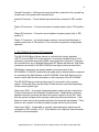
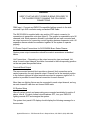
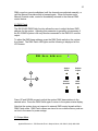
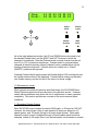
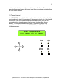
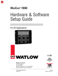
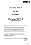
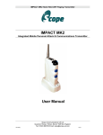
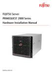
Applied Electronics
Bravo Series Dimming System
Rack-Mount Architectural
Model SA12/2400A and
Model SA12/2400E
Setup and Operation
Instructions
1.0 Scope
This document details the setup and operation requirements for Applied
Electronics Bravo Series Dimming System. These Instructions are provided for
the Model SA12/2400A rack mount architectural dimmer unit.
2.0 General
Applied Electronics Bravo Series Dimming System consists of a 3 space rack
mountable chassis with user interface on the front panel (see Figure 1). The
SA12/2400A provides the capability to control up to ninety-six 2400 watt outputs,
with the use of expansion units (SA12/2400E).
Dim levels for each system output may be controlled by any of the following
methods:
1. Any DMX512-compatible lighting console.
2. Local control assumed from the front panel of the SA12/2400A.
3. Any Applied Electronics WP Series Wall Stations
Internal temperatures are continuously monitored in each unit. If an over
temperature condition is sensed, all outputs within that unit are turned off until the
system is reset.
The SA12/2400A Bravo Series Architectural Dimmer is available with terminal
block output connections. Other types of output connectors are available on
request. Each Dimmer is user defined at date of purchase.
The front panel of the SA12/2400A has a 2 x 24 character LCD for system status,
individual channel load-light indicators and pushbutton controls for easy set-up of
system parameters (see figure 1). The SA12/2400E has only a Power indicator
and an Over Temperature indicator (see figure 2).
Each SA12/2400A and SA12/2400E is provided with a standard one-year
warranty for parts and labor.
2
Figure 1
SA12/2400A (front view)
Master Unit
Figure 2
SA12/2400E (front view)
Expansion Unit
Applied Electronics • 722 Bluecrab Road • Newport News, VA 23606 • (800) 883-0008
3
Figure 3
SA12/2400A (rear view)
Master Unit
Figure 4
SA12/2400E (rear view)
Expansion Unit
Applied Electronics • 722 Bluecrab Road • Newport News, VA 23606 • (800) 883-0008
4
3.0 Specifications
- Input Voltage: 220VAC (120VAC x 2) or 208VAC (3-phase)
- Input Current: 240A per panel, supplied as 120A x 2 (for single phase
sources) or 80A x 3 (for 3-phase sources)
- Dimming Outputs: 12 channels @ 2400W (up to 60 channels w/
expansion dimmers)
- Weight: 56 lbs.
- Outside Dimensions: 5.22“ high x 19“ wide x 17.5“ deep
- Operational Ambient Temperature: 32o to 104o F (0o to 40o C)
4.0 Chassis Mounting
Each SA12/2400A and SA12/2400E dimmer unit is intended to be mounted in a
standard 19” rack enclosure. Note that all dimmers are inherently noisy devices,
and care should be taken not to mount the panels in a location where audible
noise could be a distraction.
For cooling considerations an exhaust fan for the Bravo Series dimmers is
located on the left side (looking at the front of the unit). The right side of the
dimmer has an intake fan. When mounted in a rack enclosure insure proper
venting of each unit is allowed by having 2” diameter min. vent holes in rack side
panel adjacent to the exhaust vent of the SA12/2400A (E).
*Allow 6” minimum clearance between racks if two or more racks are to be
located side-by-side
Rear rack mounting rails are recommended for rear support of each dimmer unit.
Rear mounting ears are available for the Bravo Series dimmers which will allow
the unit to be secured to the rear mounting rails.
5.0 System Wiring Details
The following sections detail control and power wiring requirements for the Bravo
Series Dimmer Unit.
5.1 Power Input Connections for the Bravo Series Dimmer
The Bravo Series Dimmer Unit may be configured for use with 3-phase or singlephase power sources. Your dimmer unit is normally shipped configured for three
phase operation. In 3-phase mode, all blue wires marked with black and red tape
should be connected to TB1 position 1 (second from right – from front of unit). In
single-phase configuration, blue wires with black marking tape should be
connected to TB1 position 3 (with other existing black wires) and blue wires with
Applied Electronics • 722 Bluecrab Road • Newport News, VA 23606 • (800) 883-0008
5
red marking tape should be connected to TB1 position 2 (with other existing red
wires). The resulting phase/channel assignments for each configuration are as
follows:
Configuration
3-Phase
Single Phase
1
A
A
2
B
B
3
C
B
Channel Phase Assignment
4
5
6
7
8
9
A
B
C
A
B
C
A
B
A
A
B
B
10
A
A
11
B
B
12
C
A
WARNING
VERIFY THAT NO INPUT POWER IS BEING PROVIDED TO
THE CHASSIS PRIOR TO MAKING THE FOLLOWING
CONNECTIONS.
System power input connections should be made in accordance with Figure 3
and as detailed below.
Ground
Neutral
Phase A
TB1
Phase B
Phase C
Figure 3
Power Input Connections
Applied Electronics • 722 Bluecrab Road • Newport News, VA 23606 • (800) 883-0008
6
Ground Connection – Earth ground input should be connected to the .ground lug
located next to the power input terminal block.
Neutral Connection – Power Neutral input should be connected to TB1 position
4.
Phase A Connection – Connect one phase of system power (hot) to TB1 position
1.
Phase B Connection – Connect a second phase of system power (hot) to TB1
position 2.
Phase C Connection – In 3-phase power systems, connect the third phase of
system power (hot) to TB1 position 1. No connection required for single phase
operation.
5.1 SA12/2400A (E) Control I/O Connections
The SA12/2400A Bravo Series dimmer is controlled by industry standard
(USITT), five pin DMX-512 control protocol. An industry standard five pin XLR
connector is provided along with a DMX output (loop-thru) connector. It can also
be controlled from any of Applied Electronics WP Series wall stations. Wall Plate
connections are made to the SA12/2400A via an eight position terminal block.
Wall Station connections are clearly labeled on the rear panel of the
SA12/2400A. A 22 AWG, twisted two-pair cable with an internal shield is required
for connecting the Wall Stations to the SA12/2400A. Each Wall Station is to be
wired in series with the final termination on the rear panel of the SA12/2400A.
The SA12/2400 also provides an alarm input for connection into a security
system. A Normally Open and Normally Closed terminal is provided depending
on the security system type.
Alarm Input (N/C) – A normally closed alarm/panic switch may be connected to
Common terminal and the Normally Closed terminal. Breaking the connection
between these two terminals will cause all system outputs to go full ON. Note
that the system is shipped with a jumper connecting these two positions. If this
feature is used, remove this jumper and wire to the terminals as indicated. If this
feature is not required, the factory-installed jumper should be left in place.
Alarm Input (N/O) – If applicable, a normally open alarm/panic switch may be
connected to TB1 positions 14-15. If this feature is not required, these terminals
should be left unconnected.
Applied Electronics • 722 Bluecrab Road • Newport News, VA 23606 • (800) 883-0008
7
WARNING
VERIFY THAT NO INPUT POWER IS BEING PROVIDED TO
THE CHASSIS PRIOR TO MAKING THE FOLLOWING
CONNECTIONS.
DMX Input – Connect any DMX512-compatible lighting console to the sidemounted 5-pin XLR connector using a standard DMX cable.
The SA12/2400A is supplied with a six position XLR output connector for
connections to expansion units (see figure 2). The system is expandable up to 96
channels total. Each expansion dimmer is provided with an input connector and
an output connector for connecting control signaling between expansion units. All
expansion dimmer should be connector together for the system to operate
properly.
5.3 Power Output Connections for SA12/2400A Bravo Series Dimmer
System power output connections should be made in accordance as detailed
below.
Hot Connections – Depending on the output connection type purchased, Hot
wires for each output channel should be connected to the corresponding position
on the rear panel as specified below.
Terminal Block Output:
The rear mounted terminal block provides a channel (hot) connection and a
neutral connection for each channel output. Channel one is the terminal position
to the furthest right and all other terminals are wired in sequence right to left. A
position is provided for each Neutral connection for each channel.
More than one lighting fixture may be connected to each output channel, as long
as each channel’s load does not exceed 2400 watts.
6.0 System Setup
After all system control and power wiring are connected as detailed in section 5
above, turn all 12 output channel circuit breakers OFF, turn your DMX-512
lighting console OFF and energize the system.
The system front panel LCD display should display the following message for a
few seconds:
Applied Electronics • 722 Bluecrab Road • Newport News, VA 23606 • (800) 883-0008
8
Applied Electronics
SA12/2400 Dimmer
Output
Mode
Manual
Override
Preheat
Adjust
DMX
Patch
After initialization, the LCD will display the following system status screen:
A:OK
B:OK
C:OK
Valid DMX: No
Valid DMX Input: NO
Temp:NORM
Base: 1
Base
Output
Mode
Manual
Override
Preheat
Adjust
DMX
Patch
Note: If the system is powered by a single phase (220/240 VAC) source, the LCD
will not display the “C: OK” message.
With all sliders set to “0” or “OFF”, turn on the DMX512 lighting console. The
status message should change to “Valid DMX Input: YES”.
Applied Electronics • 722 Bluecrab Road • Newport News, VA 23606 • (800) 883-0008
9
6.1 Manual Override
The Manual Override function allows the user to override DMX control input and
adjust each output individually. Turn ON the front panel circuit breaker for Output
Channel 1 (the leftmost breaker). The fixture connected to Output 1 should
remain OFF. Press the front panel Manual Override button. The Manual
Override LED should light, and the LCD will display the following:
Chan: 01 02 03 04 05 06
Level: 00 00 00 00 00 00
Output
Mode
Manual
Override
Preheat
Adjust
DMX
Patch
The top row of numbers in the LCD display indicates channel output numbers.
The bottom row indicates the current level of each output. A flashing cursor
(shown in the figure with a gray background) indicates the current output
channel. Press the UP and DOWN buttons to the left of the Manual Override
switch to change the value of Output 1 from 0% to 100%. (Note: 100% level is
displayed as “FL” for “Full” on the LCD display.) Verify that the lighting fixture(s)
connected to Output 1 light and dim accordingly. To adjust another output
channel, turn on the corresponding front panel circuit breaker, press the LEFT
and RIGHT buttons to the left of the Manual Override switch to select the desired
channel, then use the UP and DOWN buttons as above to adjust the output level.
Repeat these steps until all output channels have been verified.
Pressing the Manual Override switch again causes the associated LED to
extinguish and the LCD to revert to the system status screen.
Note that when the system is in normal usage, pressing the Manual Override
button causes all outputs to freeze at their current levels (as set externally by the
Applied Electronics • 722 Bluecrab Road • Newport News, VA 23606 • (800) 883-0008
10
DMX console or remote wallplates) until the channels are adjusted manually, or
until the Manual Override switch is pressed again. When the system exits
Manual Override mode, control is immediately returned to the external DMX
control device.
6.2 DMX Patch
The SA12/2400 DMX Patch function allows the user to adjust the base DMX
address for the system. Adjusting this parameter is generally not necessary if
the SA12/2400 system is the only dimmer connected to the DMX-512 console
output.
To adjust the DMX base address, press the DMX Patch switch on the system
front panel. The DMX Patch LED lights and the following is displayed on the
LCD screen:
DMX Base Address:
1
Output
Mode
Manual
Override
Preheat
Adjust
DMX
Patch
Press UP and DOWN arrows to adjust the system DMX base address to the
desired value. Press the DMX Patch again to return to the system status display.
Note that the system does not respond to external DMX control signals while in
DMX Patch mode. DMX Patch values are stored in non-volatile memory and are
not lost in the case of a power outage.
6.3 Output Mode
Applied Electronics • 722 Bluecrab Road • Newport News, VA 23606 • (800) 883-0008
11
The SA12/2400 Output Mode performs two important functions: (1) Channels
may be set to operate in non-dimming mode (also called “switch” or “relay”
mode), and (2) Channels may be grouped together so that changing the level on
one channel changes the level on all channels equally.
Press the Output Mode switch on the SA12/2400 front panel. The Output Mode
LED should light, and the LCD will display the following:
Chan: 01
Level: D
02
D
03
D
04
D
05
D
Output
Mode
Manual
Override
06
D
Preheat
Adjust
DMX
Patch
The “D” under each output channel indicates that associated channel is set to
“Dim” mode. This is the default operating mode for each channel. Pressing the
UP button once changes the selected channel’s output mode to “S”, indicating
“switch” mode. When an output channel is in Switch mode, the output level of
that channel changes from OFF when the input control signal is at 50% or less,
to full ON when the input level is set to greater than 50%. This feature allows
non-dimmable (on/off) devices to be controlled by the dimming system.
Pressing the UP button again changes the selected channel’s output mode to “<”,
indicating that that channel’s level will track the level of the preceding channel.
This feature is useful when it is preferable to use one channel level to control
several outputs simultaneously, particularly in cases where a group of lights
should always be at the same level but (because of their power consumption)
must be assigned to several separate outputs. It also permits a single slider on a
remote wallplate controller to raise and lower the brightness of a group of lights.
Applied Electronics • 722 Bluecrab Road • Newport News, VA 23606 • (800) 883-0008
12
Consider the following sample display:
Chan: 01 02 03 04 05 06
D/S: D < < < D D
Output
Mode
Manual
Override
Preheat
Adjust
DMX
Patch
When set up as shown, Output Channels 1 through 4 will dim as determined by
the input level for Channel 1, Channels 6 through 8 will dim as determined by the
input level for Channel 6, and Channels 11 and 12 will switch ON and OFF as
determined by the input level for Channel 11. Channels 5, 9, and 10 will operate
independently of all other channels.
Pressing Output Mode again causes the Output Mode LED to extinguish and the
system status screen to be displayed. Output Mode settings are saved in nonvolatile memory and are not lost in the case of a power outage.
6.3 Preheat Adjust
The SA12/2400A Preheat Adjust function allows users set to a minimum value
for the output level of individual channels. This feature has two benefits: (1)
Bulb life is extended for fixtures that are frequently taken from full OFF to full ON
repeatedly, and (2) Bulbs reach full brightness more quickly when they begin with
a small trickle current running through them. These benefits are most noticeable
in fixtures that are used in “Chase” mode (see DMX lighting console instructions).
To set preheat values, press Preheat Adjust on the system front panel. The
Preheat Adjust LED should light, and the LCD will display the following:
Applied Electronics • 722 Bluecrab Road • Newport News, VA 23606 • (800) 883-0008
13
Chan:
Preht:
01 02 03 04 05 06
00 00 00 00 00 00
Output
Mode
Manual
Override
Preheat
Adjust
DMX
Patch
As in the other adjustment modes, the UP and DOWN buttons are used to set
the desired Preheat level, and the RIGHT and LEFT buttons to select the
channel to be adjusted. Note that Preheat levels for each channel may be set
from 0% to 12% of maximum brightness. Preheat levels for grouped output
channels all track the primary (lowest) channel’s value; preheat levels for the
tracking channels are ignored. Preheat values for outputs set to “Switch”
(ON/OFF) mode are also ignored.
Pressing Preheat Adjust again causes the Preheat Adjust LED to extinguish and
the system status screen to be displayed. Preheat Adjust settings are saved in
non-volatile memory and are not lost in the case of a power outage.
7.0 Maintenance Issues
When properly mounted and wired as specified herein, the SA12/2400 Bravo
Series Dimmer system should provide years of trouble-free service. However,
certain failure conditions may cause the unit to malfunction or cease operation
completely. This section provides an overview of the most common failure
conditions.
7.1 Excessive System Current
Each SA12/2400 output channel is rated at 2400 watts, or 20 amps at 120 VAC.
However, the total current rating of each panel is 80 amps per phase for a 3phase system, and 120 amps per leg for a single phase system. While each
channel’s output current is supplied through a circuit breaker which limits that
channels’ current to 20 amps, there is no internal master circuit breaker to ensure
Applied Electronics • 722 Bluecrab Road • Newport News, VA 23606 • (800) 883-0008
14
that the system’s total current draw is within the specified limits. Before
operating the system, be sure that power input lines are externally protected from
an over current condition.
7.2 Thermal Overload
Each SA12/2400A is supplied with thermal monitoring circuitry which continually
monitors the unit’s internal temperature. If air pathways into or out of the chassis
are blocked, if the unit’s side-mounted heat sinks are covered, or if the unit is
mounted too close to nearby walls or heat sources (such as other dimmer
panels), it is possible for the dimmer system to overheat. When an over
temperature condition is sensed in the SA12/2400A, the LCD displays the
following message:
Over Temperature
Turn Power Off to Reset
Output
Mode
Manual
Override
Preheat
Adjust
DMX
Patch
Applied Electronics • 722 Bluecrab Road • Newport News, VA 23606 • (800) 883-0008