1
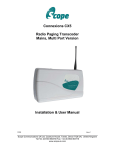
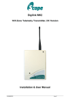
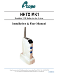
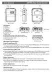
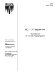
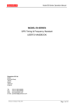
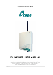
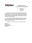
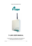
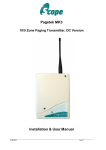
IMPACT MK2 Hand Held UHF Paging Transmitter
IMPACT MK2
Integrated Mobile Personal Attack & Communications Transmitter
User Manual
Scope Communications UK Ltd
Quantum House, Totnes, Devon TQ9 5AL England.
Tel: 01803 860700 Email: [email protected]
HHTXMK2
Issue 1
IMPACT MK2 Hand Held UHF Paging Transmitter
PREFACE
Important Installation Information
It is the purchasers’ responsibility to determine the suitability of this equipment and its derivatives for any
given application, Scope cannot give specific advice in this manual, as each use will require independent
evaluation.
Scope has, wherever possible, employed extra safeguards to monitor the system’s performance. Certain
system installations, operational requirements or budgets may, however, limit the effectiveness of these
safeguards. Again, the suitability of the system for any given application must therefore be decided by the
installer and their customer, relative to the application and risk.
Good working practice dictates that a suitable system installation log must be generated, together with a
record of the dates when the system has been manually checked, (with the aid of signal strength meters
etc.) enabling the system performance to be compared with the original installation data.
For UK equipment, Scope has no control of the use and application of the frequencies issued by
OFCOM. Some equipment that is licensed may have greater protection than other equipment which is
operated on a WT Act License Exempt basis.
The supply of this equipment is governed by our standard terms and conditions of sale, which can be
found on the reverse of all order acknowledgements*, proforma invoices*, delivery notes, price lists and
invoices. Alternatively, these can be provided on request.
* Faxed proforma invoices and quotations refer to “conditions available upon request”.
Important Safety Information
Scope products are designed to operate safely when installed and used according to general safety
practices. The following requirements should be observed at all times.
Do NOT subject this equipment to:
Mechanical shock
Excessive humidity or moisture
Extremes of temperature
Corrosive liquids
This equipment is designed for indoor use, unless expressly stated otherwise, and must not be used in
classified Hazardous Areas, including areas containing explosive or flammable vapours, unless express
authorisation has been given in writing by the manufacturer. If in doubt, consult your local product dealer
for further information.
Do not obstruct any slots or openings in the product. These are provided for ventilation to ensure reliable
operation of the product and to protect it from overheating.
Only use a damp cloth for cleaning (not liquid or aerosol based cleaners), and ensure that any power is
removed from the unit prior to beginning the cleaning operation.
Removal of covers from the equipment must only be undertaken by authorised service personnel, who
must ensure that power is isolated prior to removal.
Battery Charging
The Nickel Metal Hydride batteries fitted in Scope portable transmitters are optimised for safety and
performance and are NOT accessible or replaceable by the user. Where it is suspected that the batteries
are faulty or if they refuse to maintain a charge, the equipment must be returned to Scope for servicing
and battery replacement. The transmitter unit must only be re-charged using the charger receptacle and
AC adaptor provided by Scope. Use of other adaptors or chargers will invalidate all warranties and may
result in damage to the equipment and/or injury to the user. In all such cases, Scope expressly excludes
liability for any damage or injury, howsoever caused.
HHTXMK2
Issue 1
2
IMPACT MK2 Hand Held UHF Paging Transmitter
No User Serviceable Parts
Alteration or modification to any part of this equipment, without the prior written consent of the
manufacturer Scope, will invalidate all Approvals and Warranties attaching to the equipment. Further
liability for the operation of the equipment, under the applicable law, will pass to the user, who will
absolve the manufacturer of any further responsibility for it’s correct operation and use.
Liability
Scope does not accept liability for any damage or injury, howsoever caused as the result of misuse of
this equipment. It is the responsibility of the user to ensure that the equipment is operated in the manner
for which it was intended and that it is the correct item of equipment for the required task.
Warranty
This product is warranted as free from defects of workmanship and materials for a period of one year
from the original purchase date. During this time, if there is a defect or malfunction of this product, Scope
will, with proof of purchase, repair or replace at it’s discretion any defective parts, free of charge. This
does not include where the adjustments, parts and repair are necessary due to circumstances beyond
the control of Scope, including but not limited to fire or other casualty, accident, neglect, abuse, abnormal
use or battery leakage damage.
WARNING ! No User Serviceable Parts
Celui-ci ne contient aucune piece pouvant etre reparee par l’utilisateur
Caution ! Risk of electric shock, do not open.
Attention ! Risque de choc electrique, ne pas ouvrir.
Alteration or modification to any part of this equipment, without the prior written consent of the
manufacturer, will invalidate all manufacturer approvals and warranties. No adjustments can be
undertaken except by qualified and licensed persons as authorised by Scope.
WARNING ! SAFETY
The AC adaptor provided with this equipment must only be used with an Approved mains cord
set rated at 5A minimum which is fitted with an integral three prong, grounded mains plug and a
moulded IEC320 style socket. The cord set must only be plugged into a grounded, fused outlet
rated 5A minimum.
This product complies with the essential requirements of the R&TTE Directive 1999/5/EC, the EMC
Directive (89/336/EEC) and the Low Voltage Directive (73/23/EEC) issued by the Commission of the
European Community.
Copies of the Declaration of Conformity covering this product can be obtained from Scope at: Quantum
House, Steamer Quay, Totnes TQ9 5AL United Kingdom.
Do not discard. At end of life this equipment must be sent to an authorised waste treatment centre.
Contact Scope at the above address for further details.
© Scope Communications UK Ltd, 2005 All Rights Reserved
System Overview
HHTXMK2
Issue 1
3
IMPACT MK2 Hand Held UHF Paging Transmitter
The Scope IMPACT MK2 is a portable UHF transmitter used to signal various types of
emergency alert to both fixed base station equipment and portable receivers.
Applications include straightforward security/panic alarm by simple button press; “lone
worker” and “man down” alerter , where a motion sensor is utilised to signal a preprogrammed level of inactivity; and “snatch” alarm, whereby a lanyard is attached
between the wearer and the IMPACT, removal of which will trigger a continuous alarm.
Modes of operation are selectable using two top plate buttons and a display, which also
indicates battery charge and alarm status.
The IMPACT is provided with an intelligent “fast” charger, facilitating full charge of the
nickel metal hydride cells in less than 1 hour (typically 40 minutes), together with an ac
adaptor, leather carry case for the IMPACT and lanyard “snatch” pin.
Package Contents:
Scope IMPACT transmitter unit, with stud mounted aerial (fitted)
Leather carry case
AC Adaptor (output: 5V dc @ 2A)
Desktop Charger base unit
Lanyard snatch pin
Programming shoe with integral lead (optional)
Programming application disk (optional)
Getting Started
Remove the components from their packaging and check that all items are present.
Locate the AC adaptor and insert the power jack into the socket at the rear of the
charger base unit. Fit the mains lead supplied between the adaptor and a 110V mains
outlet. The green power light on the charger base should now be lit and the red status
light should be off.
Switch on the IMPACT by pressing and holding the uppermost blue side button together
with the uppermost scroll button. The display will show the current mode number setting
and a “sign on” transmission will be sent, which may be received by suitably configured
pagers or fixed receivers. Now place the IMPACT into the charger base, checking that
the silver contacts on the side of the unit face the same way as the silver contacts in the
charger base. A “sign off” transmission will be sent, after which the unit’s normal
operating functions will be disabled and the unit will lock into charging mode.
The display on the top face of the IMPACT will light and the words “FAST CHRG” will
be displayed. “FAST” will flash on/off and the battery icon will pulse, indicating that rapid
charging is in progress. The red light on the charger base will flash during the charging
process.
HHTXMK2
Issue 1
4
IMPACT MK2 Hand Held UHF Paging Transmitter
When full charge is achieved, the red light on the charger base will glow steady and the
transmitter display will now show “CHRG” with the battery icon filled. Upon removal
from the charger, the unit will transmit a “sign on” message indicating that it is now
available for operation.
Note: where cells are completely discharged, the unit should be placed in the charger
and the uppermost side-mounted blue button (A) pressed together with the uppermost
display scroll button until the display lights (usually a few seconds). Normal charging will
then resume. If the display blanks when the buttons are released, press and hold the
buttons for a further few seconds until normal charging resumes.
Precaution: to minimise any potential for malfunctioning of the unit in a severe static
electricity environment, users should avoid touching the charger contacts and aerial
mount collar. It is therefore recommended that the unit is placed in it’s carry case
immediately after charging.
Operation
Switching the Unit ON/OFF
To switch ON, press and hold the uppermost side-mounted blue button (A) and then
press the uppermost display scroll button. The display will activate and show the current
mode number and battery status.
To switch OFF, press and hold both the scroll buttons until the display flashes. Now
scroll down until FF is displayed. After 2 seconds, the unit will switch off. Note: if the unit
has been programmed in Mode 4, this prohibits user access and will bar the user from
switching the unit off.
Modes of Operation
The IMPACT has three manual call types selectable from two blue buttons (A & B)
located on the side of the unit, and a further two emergency alarms which consist of a
“snatch” lanyard and a motion detector. Whilst the manual button-initiated alarms are
always active, both the lanyard and the motion detector can be enabled or disabled by
selection of the relevant mode on the unit’s display.
This also allows different motion sensor countdown periods (short/medium/long) to be
selected.
The display will indicate which mode is active at any time, and the mode can be
changed by using the scroll keys located on the top of the unit (next to the display).
Either key must be pressed and held for 2 seconds. This will cause the LCD display to
flash the two digits, and the scroll buttons can then be used to select the required Mode
number. After 2 seconds of no button activity, the displayed Mode will be set.
HHTXMK2
Issue 1
5
IMPACT MK2 Hand Held UHF Paging Transmitter
Mode 1 Buttons A & B
Mode 2 Buttons A & B + lanyard
Mode 3 Buttons A & B + motion sensor
Mode 4 Buttons A & B + lanyard + motion sensor
Mode 5 Buttons A & B + lanyard + motion sensor
Mode 6 Buttons A & B + lanyard + motion sensor
Mode 7 Buttons A & B + lanyard + motion sensor
Mode 8 Buttons A & B + lanyard + motion sensor
(motion sensor & lanyard Off)
(motion sensor Off)
(lanyard Off)
(preset countdown)*
(count down Short)
(count down Medium)
(count down Long)
(count down Short, sounder Off)
*In this Mode, User Access is denied, so no other Modes will be available to the User.
Where User Access is allowed, Modes 1, 2, 3, 5, 6, 7 & 8 will be available.
Mode 1 – Manual Alarms Only
The uppermost side-mounted blue button (A) will send a zone 1 alarm when pressed
and held for a predefined period of time (set during programming). The lower sidemounted blue button (B) sends a zone 2 alarm. Pressing both buttons together (A+B)
and holding them for the trigger period will send a zone 3 alarm.
Mode 2 – Manual Alarms and Lanyard Active
The pin in the base of the unit is intended to be connected to a lanyard attached to the
wearer. If the transmitter is pulled away from the wearer the pin will be released and an
automatic Zone 4 alarm is immediately sent. This will continuously repeat for 500
transmissions or until the pin is replaced.
Mode 3 – Manual Alarms & Motion Sensor Active
This mode enables blue buttons A & B and the motion sensor. The motion sensor “no
movement” and warning countdown periods are preset using the programming
application software. If you do not have the programming software, refer to your
distributor for all configuration settings. If the unit detects no motion for the preset time,
it will pulse a sounder for a further preset time as a warning before transmitting a Zone
5 alarm. Any movement detected during these warning periods will reset the timers.
The motion detector is most sensitive with the unit vertical and less sensitive as the unit
is rotated to the horizontal plane. It is intended that the user should wear the unit on a
belt or sash as near to vertical as possible (with the antenna facing upwards).
Mode 4 Preset and Locked: all Alarms Active
In this mode, all alarms are active and preset at the factory. Refer to your distributor for
the preset configuration. The user is barred from accessing any other modes and does
not have the ability to switch the unit off.
HHTXMK2
Issue 1
6
IMPACT MK2 Hand Held UHF Paging Transmitter
Mode 5 All Alarms Active with Short Countdown
The motion sensor “no movement” period is preset to a short time (refer to your
distributor for the actual time period set). All other alarms are active.
Mode 6 All Alarms Active with Medium Countdown
As above with medium preset motion sensor “no movement” period (refer to your
distributor for the actual time period set). All other alarms are active.
Mode 7 All Alarms Active with Long Countdown
As above with long preset motion sensor “no movement” period (refer to your distributor
for the actual time period set). All other alarms are active.
Mode 8 All Alarms Active with Short Countdown & Sounder off
As in Mode 5, but with the warning countdown beeper turned off.
Programmed Variables
It is important that the user is provided with a Configuration sheet which details how all
the various parameters have been programmed. The variable features are as follows:
a) Trigger time: this is the time that the A & B buttons need to be held in before the
alarm is sent. The hold time for each button can be preset between 0.1 and 9.9
seconds.
b) Messages: unique text messages can be programmed for each alarm zone (up to 65
characters). In addition, a User name of up to 13 characters can be entered. This User
name will precede the zone message when displayed on a pager e.g. “Fred Smith:
Emergency Code Red”
c) Sounder: for each alarm zone, the sounder can be programmed as Off, Normal or
Quiet.
d) Motion sensor sensitivity: this can be preset as Fine, Normal or Coarse.
e) Motion sensor “no movement” time: this can be preset as Short, Medium or Long.
Short = 5-29 seconds. Medium = 30-120 seconds. Long = 3-30 minutes.
f) Motion sensor “warning” time: this is the beeper warning time before the alarm is
transmitted, settable as 10, 20 or 30 seconds.
g) Repeat transmissions: for the A & B buttons, repeat calls can be preset between
1-999.
h) Test calls: the unit can be programmed to send Test calls at preset intervals between
10-50 minutes (with 10 minute increments) and 1-24 hours (with 1 hour increments).
i) Reset: both the lanyard & motion sensor can be programmed to send a Reset
transmission upon de-activation (i.e. when the lanyard pin is replaced or when motion
resumes).
J) Motion sensor Off warning: if the user selects a mode where the motion sensor is
disabled, the unit can be programmed to beep every 5 minutes as a reminder that the
sensor is disabled.
Please refer to your distributor for details of how these variables have been set on your
unit(s). A sample Configuration Sheet is included in Appendix A of this manual.
HHTXMK2
Issue 1
7
IMPACT MK2 Hand Held UHF Paging Transmitter
IMPACT Top Control Panel
Battery Status
Mode Indicators
Increment Scroll Button
Transmit Indicator
FAST CHRG
Decrement Scroll Button
Sounder On indicator
Motion Sensor
Rapid Charge Indicator
IMPACT & Charger Details
HHTXMK2
Issue 1
8
IMPACT MK2 Hand Held UHF Paging Transmitter
Battery Capacity
The batteries are 1.6Ah Nickel Metal Hydride cells. The number of hours operation on a
full charge is totally dependant upon the type of use to which the unit is put.
Transmissions use by far the greatest power, but with test calls set at 1 hour, the cells
should last several days between charges. Turning off the unit between use is
recommended, but it should be noted that long periods of no use will still reduce the
battery charge.
The battery indicator on the display will show the approximate capacity left in the cells.
At a preset point the unit will transmit a “Battery Low” message, flash the display
backlight and beep (if selected). When the battery voltage falls below that required to
run the transmitter, the unit will flash the display and the battery icon, then it will
automatically switch itself off, since it cannot perform its intended function without a
transmitter. It will then need recharging before it can be used again.
Specification
Power:
2.4V (1.2V x 2) NiMh cells, sealed pack
System Power Consumption:
less than 2mA (standby), 180mA (transmit)
Charger Input:
5 V dc @ 2A
Transmitter:
Power output:
500mW max
Frequency Range:
450-470 MHz
Channel Spacing:
12.5 KHz
TX Baud Rate:
1200
RF Standards applied:
ETS 300 220
Type Designation:
MOBILINK
Notified Body Ref. No:
0891
EMC Standards applied:
EN 301 489-1 V1.4.1
LVD Standards Applied
EN 60950: 2000
Scope’s policy is one of continuous development and specifications are subject to change without notice
HHTXMK2
Issue 1
9
IMPACT MK2 Hand Held UHF Paging Transmitter
Appendix A
System Configuration (Default Screen shown)
HHTXMK2
Issue 1
10