1
Ultrashifter
V2.300 Upgrade for the 4000 series
User Manual
Part No: 135010
Manual Release 1.0
©1999 Eventide Inc., One Alsan Way, Little Ferry, NJ, 07643 USA
31 August, 1999
Harmonizer is a registered trademark of Eventide Inc. for its audio special effects devices incorporating pitch shift.
Orville and Ultrashifter are trademarks of Eventide Inc.
This page intentionally left blank.
Contents
This upgrade adds three Banks with 18 presets and 23 new modules to the 4000 or 4500. 4000 users
without the optional sampler (standard in the 4500) will see sampler presets in Banks 32-34 but will
not be able to use them.
The Ultrashiftertm is the first of a new generation of pitch shifters specially designed for vocal use. It
may give interesting results on other material but this cannot be guaranteed.
Ultrashifter Presets . . . . . . . . . . . . . . . . . . . . . . . . . . . . . . . . . . . . . . . . . . . . . . . . . . . . . . . . . . . . . . . . 3
Ultrashifter Preset parameters . . . . . . . . . . . . . . . . . . . . . . . . . . . . . . . . . . . . . . . . . . . . . . . . . . . . . . . 4
Midiclock Presets . . . . . . . . . . . . . . . . . . . . . . . . . . . . . . . . . . . . . . . . . . . . . . . . . . . . . . . . . . . . . . . . . . 6
Dither Presets . . . . . . . . . . . . . . . . . . . . . . . . . . . . . . . . . . . . . . . . . . . . . . . . . . . . . . . . . . . . . . . . . . . . . 6
....................................................................................
Modules . . . . . . . . . . . . . . . . . . . . . . . . . . . . . . . . . . . . . . . . . . . . . . . . . . . . . . . . . . . . . . . . . . . . . . . . . . . .
c_ftop . . . . . . . . . . . . . . . . . . . . . . . . . . . . . . . . . . . . . . . . . . . . . . . . . . . . . . . . . . . . . . . . . . . . . . . . . . . . 7
c_graph
.......................................................................... 7
c_lin2db . . . . . . . . . . . . . . . . . . . . . . . . . . . . . . . . . . . . . . . . . . . . . . . . . . . . . . . . . . . . . . . . . . . . . . . . . . 8
c_many . . . . . . . . . . . . . . . . . . . . . . . . . . . . . . . . . . . . . . . . . . . . . . . . . . . . . . . . . . . . . . . . . . . . . . . . . . . 8
c_master . . . . . . . . . . . . . . . . . . . . . . . . . . . . . . . . . . . . . . . . . . . . . . . . . . . . . . . . . . . . . . . . . . . . . . . . . . 9
c_ptof . . . . . . . . . . . . . . . . . . . . . . . . . . . . . . . . . . . . . . . . . . . . . . . . . . . . . . . . . . . . . . . . . . . . . . . . . . . . 9
c_random . . . . . . . . . . . . . . . . . . . . . . . . . . . . . . . . . . . . . . . . . . . . . . . . . . . . . . . . . . . . . . . . . . . . . . . . . 10
c_relay . . . . . . . . . . . . . . . . . . . . . . . . . . . . . . . . . . . . . . . . . . . . . . . . . . . . . . . . . . . . . . . . . . . . . . . . . . . 10
c_timer . . . . . . . . . . . . . . . . . . . . . . . . . . . . . . . . . . . . . . . . . . . . . . . . . . . . . . . . . . . . . . . . . . . . . . . . . . 10
compressor . . . . . . . . . . . . . . . . . . . . . . . . . . . . . . . . . . . . . . . . . . . . . . . . . . . . . . . . . . . . . . . . . . . . . . . 11
dither . . . . . . . . . . . . . . . . . . . . . . . . . . . . . . . . . . . . . . . . . . . . . . . . . . . . . . . . . . . . . . . . . . . . . . . . . . . 12
gate2 . . . . . . . . . . . . . . . . . . . . . . . . . . . . . . . . . . . . . . . . . . . . . . . . . . . . . . . . . . . . . . . . . . . . . . . . . . . . 12
iswitch . . . . . . . . . . . . . . . . . . . . . . . . . . . . . . . . . . . . . . . . . . . . . . . . . . . . . . . . . . . . . . . . . . . . . . . . . . . 13
midiclock . . . . . . . . . . . . . . . . . . . . . . . . . . . . . . . . . . . . . . . . . . . . . . . . . . . . . . . . . . . . . . . . . . . . . . . . . 14
multiknob . . . . . . . . . . . . . . . . . . . . . . . . . . . . . . . . . . . . . . . . . . . . . . . . . . . . . . . . . . . . . . . . . . . . . . . . 15
oswitch . . . . . . . . . . . . . . . . . . . . . . . . . . . . . . . . . . . . . . . . . . . . . . . . . . . . . . . . . . . . . . . . . . . . . . . . . . 15
peak . . . . . . . . . . . . . . . . . . . . . . . . . . . . . . . . . . . . . . . . . . . . . . . . . . . . . . . . . . . . . . . . . . . . . . . . . . . . 16
picodelay . . . . . . . . . . . . . . . . . . . . . . . . . . . . . . . . . . . . . . . . . . . . . . . . . . . . . . . . . . . . . . . . . . . . . . . . . 16
scales . . . . . . . . . . . . . . . . . . . . . . . . . . . . . . . . . . . . . . . . . . . . . . . . . . . . . . . . . . . . . . . . . . . . . . . . . . . . 17
sourceanalyzer . . . . . . . . . . . . . . . . . . . . . . . . . . . . . . . . . . . . . . . . . . . . . . . . . . . . . . . . . . . . . . . . . . . . . 19
texttrigger . . . . . . . . . . . . . . . . . . . . . . . . . . . . . . . . . . . . . . . . . . . . . . . . . . . . . . . . . . . . . . . . . . . . . . . . 20
tmenupage . . . . . . . . . . . . . . . . . . . . . . . . . . . . . . . . . . . . . . . . . . . . . . . . . . . . . . . . . . . . . . . . . . . . . . . . 20
ultrashifter . . . . . . . . . . . . . . . . . . . . . . . . . . . . . . . . . . . . . . . . . . . . . . . . . . . . . . . . . . . . . . . . . . . . . . . 21
V2.300 Ultrashifter User Manual
Page 1 of 22
Release 1.0
This page intentionally left blank.
Presets
95 Ultrashifter Presets
1. Ultra AutoCorrect
This preset is a diatonic ultrashifter set as a pitch corrector, allowing you to choose which of the 12
notes are to be quantized (corrected). There is a meter displaying your source (input) as well as the
output of the analysis correction.
A diatonic pitch shifter shifts the musical pitch of an audio signal while maintaining the proper harmonic
relationship to a desired key. The pitch shifter takes care of finding out what note is being played and
automatically adjusts the amount of pitch shift so that the shifted note remains in key. Alternatively, it could be
viewed as ‘quantizing’ the pitch, or ‘pulling’ it to the nearest note in the scale.
A normal or non-diatonic shifter will shift each note by the same interval, putting some notes out of key.
2. Ultra Cents
This preset allows you to choose the amount of shift as a value in cents (100 cent to a semitone). It
has an automatic <formant> parameter, which will get you in the ballpark, but you should be aware
that all signals are different and the automatic value is meant only as a guideline. The automatic
formant value will be displayed, allowing it to be manually overridden, but will revert to its automatic
formula as you change the shift amount. So - choose the shift amount first, and then fine tune the
<formant> value for best results.
3. Ultra Cents 2
This preset is the same as 'Ultra Cents,' but has an purely manual <formant> parameter.
4. Ultra Interval
This preset is similar to 'Ultra Cents,' in that it has an automatic <formant> parameter, but differs in
that the shift amount is set as an interval. Note that the three Interval presets are non-diatonic and
therefore will not keep an interval within a 'scale' - for example, shifting up a 'perf5' means that the
output will always remain 700 cents above the input.
5. Ultra Interval 2
This is the same as 'Ultra Interval,' but has a manual <formant> parameter.
6. Ultra Interval 3
This version adds the <formant #> and <tune #> parameters, giving possible formant and tuning
values for each possible interval choice over the entire range. These allow you to pre-select the
perfect formant and tuning for each interval, enabling you to vary the interval on the fly and know
that the color of each will sound as consistent as possible.
V2.300 Ultrashifter User Manual
Page 3 of 22
Release 1.0
Presets
7. Ultra Diatonic
This preset has an automatic <formant> parameter. Being diatonic, it allows the chosen <interval> to
remain in the selected scale and key. There is also a <temper> parameter, which allows you to select
scales that are not equal tempered.
8. Ultra Diatonic 2
The same as 'Ultra Diatonic,' but with a manual-only <formant> parameter.
9. Ultra Diatonic 3
The same as 'Ultra Diatonic,' but this version adds the <formant #> and <tune #> parameters.
10. Ultra UserScales
This version has an automatic <formant> parameter. In an effort to keep these presets unencumbered
with too many parameters, we split off these three 'user scale' presets for those who want to create
their own custom scales. To define a scale you must use at least five or more notes where the first
becomes the 'key'. They must be in ascending order within an octave range from lowest note to the
highest. If there are less then five notes, or more than seven, the user scale will be ignored and a
major scale interval pattern used. You have been warned !
11. Ultra UserScale 2
This is like 'Ultra UserScale,' with a manual <formant> parameter.
12. Ultra UserScale3
This version has the <formant #> parameters.
13. RoboticVoice
This preset requires a shift amount in cents. There is a manual <formant> parameter, with, in the
addition, a <robotic> parameter. This new parameter reduces the possible range of inflection, giving a
machine-like character to the output.
Ultrashifter preset parameters:
<shift> <interval>
this chooses the amount of shift, expressed in cents or as an interval,
depending on the preset..
<mix>
The wet/dry signal mix.
<delay>
The amount of delay on the shifted signal including the built-in 50mS
processing delay.
<dry>
The amount of delay added to the dry signal. Note that setting this higher
than <delay> makes the shifted voice occur first, tricking the ear when you
are adding harmonies.
V2.300 Ultrashifter User Manual
Page 4 of 22
Release 1.0
Presets
<image>
The combined left/right panning of shifted and dry signal. 100%=shift
left/dry right.
<formant>
A percentage value that will globally alter the formant or 'character' of the
shifted signal.
<form #>
A percentage value that alters the formant for a specific interval chosen.
<tune>
In non diatonic 'Interval' presets, this is an global offset added to the
<interval> parameter.
<value>
The final displayed value of <formant> and <form #>, <tune> and
<tune#>, or the cent value of an <interval> selection.
source
<low> <hi>
Optimises the shifter by selecting upper and lower (source) limits.
<input>
The type of source material. Default, Male Speaking, Male Singing, etc.
This gives an automatic selection of <low> <hi> params.
<dampen>
Can be used to tune the vocal characteristics for troublesome material such
as telephone or radio sources.
scale/calibration
<range>
In a diatonic shifter, this is the amount below which no quantization or
‘pulling’ of the note occurs.
<speed>
How fast quantization responds in a diatonic shifter. Measured as mS per
100 cents.
<scale>
Selects the type of scale desired.
<key>
Selects the first or tonic note of the scale.
<temper>
Selects the type of tempering. Our normal western tuning is equaltempered, where the octave is split into 12 equal steps of 100 cents each.
This control allows other schemes to be selected.
<tune>
In diatonic presets, this chooses the pitch of A= measured in Hz (The
normal modern standard is A-440).
<port>
Portamento, or how much time it takes to glide from one interval to
another, measured as mS per 100 cents. The greater the change, the longer
it takes to get there.
<quantize(notes)
on-off>
In the ‘AutoCorrect’ preset, this parameter allows you to choose whether
or not you want to quantize (correct) for each of the 12 notes,
V2.300 Ultrashifter User Manual
Page 5 of 22
Release 1.0
Presets
<userscales>
In the 'UserScale' presets, this is where you create your scale.
96 Midiclock Presets
1. Midiclock Test
This is a simple program to illustrate the use of the MIDICLOCK module described on page 14.
2. Midiclock Delays 2640
These bpm style delays have stereo input and output. Midiclock sets the bpm, and you select a note
value for each delay as a rhythmic value (whole note ~ 1/32 note) which is then also displayed as a
time in mS. Global <level>, <feedback> and <image> parameters make control easy, while the
<glide> parameter lets you set the glide speed so that tempo changes can be glitch free.
3. MidiClock FM Panner
This stereo panner is extremely easy to use and very colorful. 'FM' refers to frequency modulation,
which is where one lfo (low frequency oscillator) modulates the frequency of a second lfo. To tune it,
you select a <value> for the panning (which is then also displayed as a frequency value in Hz), an <fm
depth> parameter selecting the amount of secondary modulation and lastly the <mod> or frequency
of the secondary modulation, also as a rhythmic value. It is a great way to spice up foreground or
background tracks.
4. MidiClockTremPong
This one combines a tremolo effect (selected as a rhythmic value) with a simple but powerful delay
scheme. The delay consists of a predelay feeding the ping-pong, which has a clean feedback path
outputs through a pair of ring modulators. You choose the delay time as a rhythmic value and the
pre<delay> and <pong> times are displayed as time values in mS. Because of the structure, the first
delay heard is twice the time of the subsequent 'pongs'. The <ring> and <ringmix> params are set up
for a natural chorus or beating effect to color the delays. The result is very easy to use, and a
powerful combination effect.
97 Dither Presets
1. Dither Test
This simple program allows you to dither its output to 16,18 or 20 bits. Either rectangular or
triangular dither may be selected. Preset designers may want to include this program’s functionality as
part of a larger preset, especially for mastering purposes.
V2.300 Ultrashifter User Manual
Page 6 of 22
Release 1.0
Modules
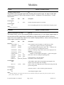
C_FTOP
GROUP: CONTROL MATH
Frequency to pitch converter
ftp
This module converts its input signal from frequency (Hz) to pitch (cents). An input of 440.0 (Hz)
produces an output of 5700.0 (cents), because A-440 is 7 semitones (700 cents) above C5 in the
octave below.
signal
Control inputs
in
Control outputs
out
Order
min
max
description
16
32767
Numeric frequency input to be converted.
The corresponding pitch cent value of the numeric frequency input.
C_FTOP, modulename, in
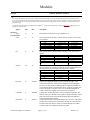
C_GRAPH
GROUP: CONTROL MATH
Graphical control input array editor
gph v2.2
This module allows you to edit an arbitrary number of points (up to 32) on a display graph control. It
also provides an offset control input to add/subtract a value from all numbers before results are
output. The screen width of the control is also variable. Displayed label (x-values) can be specified on
control inputs created for each point.
signal
min
max
description
Specifiers
screen width
8 char name
arrow text
2
{string}
{string}
4
format labels
{string}
Screen width of control in quarters. (2=half screen, 4=full)
Control name; appears in first line of graph display
Text to be displayed between point x and y. The ‘^’ character will
cause a down-arrow to be displayed in its place.
These are formatting strings for the x and y values displayed. The
standard
“%.0f” style formatting applies.
Number of control inputs (and outputs) = points on the graph.
Min & max values for editing & outputting points.
format points {string}
number points 1
point min
-32768
point max
-32768
point res
0
point 1..N
point min
Control Inputs
offset
label1..N
-32768
Control Outputs
out1..N
User Object
obj
Order
32
32767
32767
1
point max
32768
Point resolution. (in .001 increments)
The default y-values for the points.
Value added to points before being displayed & outputted. The
internal value of the point does not change.
Label (x-value) to be displayed by the format labels string when that
point is being edited.
(internal y-value N + offset ) bound by point min & max.
Actual displayed graph control
C_GRAPH, modulename, screen width, 8 char name, arrow text, format labels, format points, number points, point min, point max, point res,
point1…point N, offset, label 1…label N
V2.300 Ultrashifter User Manual
Page 7 of 22
Release 1.0
Modules
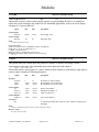
C_LIN2DB
GROUP: CONTROL MATH
Linear to dB conversion
ldb
v2.3
This module converts a linear valued control signal to its corresponding dB value. It is intended to
replace the resource-intensive log module for low bandwidth applications, such as on-screen display.
An input of 1.0 gives 0 (dB) out.
signal
Control inputs
linvalue
Control outputs
dbvalue
Order
min
max
description
0.0001
32768
Linear input value.
-90
90
dB output value.
C_LIN2DB, modulename, linvalue
Demonstration Sigfile:
HEAD "adc" adc-null adc-null "C_LIN2DB test" "Empty" 1 menupage-obj
KNOB "knob" "in: %4.2f" "in" 0.0001 32767 10 1
C_LIN2DB "c_lin2db" knob-out
MONITOR "monitor" c_lin2db-dbvalue "out %4.2f" "out"
MENUPAGE "menupage" "display" "display" 2 knob-obj monitor-obj
TAIL "njr"
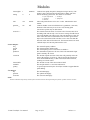
C_MANY
GROUP: CONTROL MATH
This module takes one control input and produced a number of outputs, each being a scaled
representation of the input. The relationship between the input and each output is:
outputn = inputn * multn + offsetn
This module may be used in place of c_master. Either of these modules is useful when a single knob is
used to control a number of differing parameters.
signal
Specifiers:
noutputs
inmin
inmax
Control Inputs:
in
mult 1..n
offset 1..n
Control Outputs:
output 1..n
Userobjects
obj
min
max
description
1
-32767
-32767
32
+32767
+32767
the number of control outputs
the minimum value for the input
the maximum value for the input
-32767
-32767
-32767
+32767
+32767
+32767
master control input
multiplier for output 1..n
offset for output 1..n
-32767
+32767
slave control outputs
A userobject to display the in and out values, suitable for placing on a
menupage.
Order
C_MANY modulename noutputs inmin inmax in mult1..multn offset1..offsetn
Resource Usage
low, unless very many outputs.
V2.300 Ultrashifter User Manual
Page 8 of 22
Release 1.0
Modules
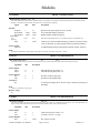
C_MASTER
GROUP: CONTROL MATH
Master control math scaling module
mst
v2.2
This module allows a single knob to generate a number of linked outputs, each one of which has a different relationship to the input. The aim of this
module is to allow a single knob or input to control many different parameters in a controllable way.
The variable number of outputs are scaled numbers, between outStartN and outStopN (inclusive) based on the input's position between inStart and
inStop (inclusive). OffsetN is added to the result, which is then forced between the boundaries of outStartN and outStopN for outputN. Thus as the
input traverses its full range (between inStart and inStop) each output will traverse its full range (between outStartN and outStopN) with an optional
OffsetN.
As an example, if the input is at instart, the value of output3 will be outstart3 + offset3. If this value is lower than outstart3 it will be set to outstart3,
similarily if is is higher than outstop3 it will be set to outstop3.
signal
Specifier
•noutputs
•instart
•instop
Control inputs
•input
•outstart1..N
•outstop1..N
•offset1..N
Control outputs
•output1..N
Order
min
max
description
1
-32768
-32768
32
32767
32767
Specifies how many units are to be created.
start of input value range.
end of input value range.
-32768
-32768
-32768
-32768
32767
32767
32767
32767
master input to be scaled and fed to outputs.
start of output value range.
end of output value range.
Offset values to be added after scaling but before bounds checking.
-32768
32767
scaled outputs.
C_MASTER, modulename, number outputs, instart, instop, in, outstart1..outstartN, outstop1..outstopN, offset1..offset1N.
The following is a sigfile which demonstrates the functioning of this module:
HEAD "adc" adc-null adc-null "C_MASTER demo" " " 1 menupage-obj
KNOB "input" "in: %3.0f" "in" -100 100 1 0
KNOB "outstart" "start: %3.0f" "instart" -100 100 1 0
KNOB "outstop" "stop: %3.0f" "outstop" -100 100 1 50
KNOB "offset" "off: %3.0f" "offset" -100 100 1 0
C_MASTER "c_master" 1 0 50 input-out outstart-out outstop-out offset-out
MONITOR "output" c_master-output1 "out: %3.1f" "out"
MENUPAGE "menupage" "" "" 5 input-obj outstart-obj outstop-obj offset-obj output-obj
TAIL "njr"
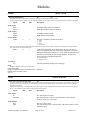
C_PTOF
GROUP: CONTROL MATH
Pitch to frequency converter
ptf
v2.2
This module converts its input signal from pitch (cents) to frequency (Hz). An input of 5700.0 (cents) produces an output of 440.0 (Hz), because
A-440 is 7 semitones (700 cents) above C5 in the octave below. This module is the converse of c_ftop.
signal
Control inputs
in
Control outputs
out
Order
min
max
description
0
13162
Incoming numeric pitch.
The corresponding frequency Hz value of the incoming numeric pitch
C_PTOF, modulename, in
V2.300 Ultrashifter User Manual
Page 9 of 22
Release 1.0
Modules
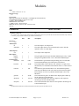
C_RANDOM
GROUP: CONTROL MATH
Random number generator rnd
v2.2
This module produces a specified number of random numbers. The numbers on each output are unique and range from 0 to the maximum number
specified. A reset input is provided to allow the sequence to be restarted from the beginning.
signal
Specifier
noutputs
min number
max number
Control inputs
reset
beginning.
min
max
description
1
-32768
-32768
32
32767
32767
Specifies how many outputs are to be created.
Lowest random number generated.
Highest random number generated.
32767
When this number changes from 0 to 1, the random sequence is restarted from the
32767
Control cycles between random numbers generated. 0 means no delay,
32767 is max delay (a really long time between generated numbers.)
-32768
delay
0
Control outputs
rand1..N
Order
A random number between min number and max number, inclusive.
C_RANDOM, modulename, number outputs, min number, max number, reset, delay, rand1, rand2 … randN
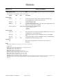
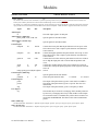
C_RELAY
GROUP: CONTROL PROCESS
Rear panel control access
rly
v2.3
This module will allow direct control of the rear panel relays, as well as direct output of the status of the rear panel SW (jack) input.
signalmin
Control Inputs:
relay1
relay2
Control Outputs:
tip
ring
Userobjects
obj
max
description
0
0
1
1
will make the tip relay when 1.0
will make the ringrelay when 1.0
0
0
1
1
the status of the tip SW input.
the status of the ringSW input.
A userobject to display the in and out values, suitable for placing on a
menupage.
Order
C_RELAY, modulename, relay1,relay2
Resource Usage
low
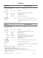
C_TIMER
GROUP: CONTROL PROCESS
Real time clock/timer
tim v2.2
This module will produce an output in seconds showing how long the RUN input was 1.0. If RESET goes from below 1.0 to 1.0 the output will be set
to zero. It will be found useful for timing external events with reasonable accuracy, such as tap-tempo controls.
signalmin
Control Inputs:
run
reset
Control Outputs:
Out
max
description
0
0
1
1
count when equal to or above 1.0
set count to zero on +ve edge
0
32767
The count in seconds
V2.300 Ultrashifter User Manual
Page 10 of 22
Release 1.0
Modules
Order
C_TIMER modulename run reset.
Resource Usage
Low
Example Sigfile:
HEAD "adc" adc-null adc-null "Stopwatch" "" 3 texttrigger-obj reset-obj monitor-obj
TEXTTRIGGER "texttrigger" 2 c_flop-out "run" "stop"
C_FLOP "c_flop" 0 0 texttrigger-out
TRIGGER "reset" "reset" "reset"
C_TIMER "c_timer" c_flop-out reset-out
MONITOR "monitor" c_timer-out "Time: %4.2f secs" "time"
TAIL "njr"
COMPRESSOR
GROUP: DYNAMIC
Soft Knee Compressor
cpr
This a dynamic range compressor with separate inputs for the signal whose gain is to be processed and for the the detection (sidechain) input. It features
a ‘soft knee’, giving a smooth translation or gain around the threshold point.
signal
min
max
description
-1
-1
1
1
The audio input to be compressed.
The audio input whose level is measured and is used to alter the
dynamics of the "in" audio input.
-1
1
The output of the compressor.
-1
-1
1
1
The gain applied to the signal. Includes additional gain set by control.
The gain in logarithmic terms. Does include the additional gain.
-100
0 dB
0
24 dB
The threshold at gain reduction begins taking place. For sidechain
below this threshold, the gain of the input is not affected.
The width (in dB.) of the soft knee. The soft knee is a region, above
the threshold, over which the ratio transitions from 1:1 to the selected
ratio.
The amount of gain reduction that occurs the sidechain input has
gone above the threshold. The value entered selects how many dB of
gain reduction occur for every dB the sidechain input is above the
threshold.
This control allows gain to be added to the output signal to make up
for the gain lost by gain reduction.
This control determines how fast the compressor will respond to
increasing level at the sidechain input.
This control determines how fast the will respond to decreasing level
at the sidechain input.
Specifiers:
none
Audio Inputs:
In
Sidechain
Audio Outputs:
out
Mod outputs:
lingain
loggain
Control Inputs:
threshcntl
kneecntl
ratiocntl
1
100
gaincntl
0
24 dB
attackcntl
0
10.0 secs.
decaycntl
0
10.0 secs
Order:
COMPARATOR modulename in sidechain threshcntl kneecntl ratiocntl gaincntl attackcntl decaycntl
V2.300 Ultrashifter User Manual
Page 11 of 22
Release 1.0
Modules
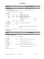
DITHER
GROUP: MATH
Dithering/Requantization
dit
v2.3
This module is intended to reduce the word length of an audio signal, with minimum reduction in quality.
The requested dither signal is added to each of the stereo input channels, and the samples are then re-quantized to the desired resolution (word length).
signal
Audio inputs
leftin
rightin
Audio outputs
leftout
rightout
Control inputs
wrdlen
min
max
description
Left input Audio stream to be dithered.
Right input Audio stream to be dithered.
Left dithered Audio stream.
Right dithered Audio stream.
0
3
The new resolution to quantize the audio to.
0 – 16 bits
1 – 18 bits
2 – 20 bits
3 - 24 bits (Off)
Choosing 24 bits doesn’t affect the input audio stream and therefore it appears as if the module is turned off, even though the processing still takes
place, using the same amount of DSP resources.
dither
0
1
Controls the distribution of the dither noise. The user can choose
between rectangular (uniform) or triangular distribution. Triangular
distribution being more common, it is set as default. Rectangular noise
distribution can be used for audio streams that have already been
processed with a rectangular dither noise.
0 – Rectangular dither
1 – Triangular dither
Userobjects
obj
Order
All of the parameters arranged in a menupage.
DITHER, modulename, leftin, rightin, wrdlen, dither.
Demonstration Sigfile:
HEAD "adc" dither-leftout dither-rightout "Dither Test" "" 1 dither-obj
DITHER "dither" adc-left adc-right 0 0
TAIL "njr"
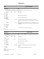
GATE2
GROUP: DYNAMIC
Audio Noise Gate with sidechain input.
gat
This module implements a noise gate function with a separate sidechain input, allowing the dynamics of one signal to control another. This feature will
typically be used to remove background noise resulting from processing, with the sidechain input connected before the process, and the signal input
being the processed signal.
If the sidechain input is below a specified threshold it will silence (gate) the output. Adjustable attack and release times control how fast the gate will
turn on or off. Suitable use of these makes the gating function much less audible.
signal
min
Audio Inputs:
In
Sidechain
Audio Outputs:
Out
Gain
V2.300 Ultrashifter User Manual
max
description
The audio input to be gated.
The audio input whose level is measured and is used to alter the
dynamics of the "in" audio input.
The noise gated output.
The gain envelope used to gate the audio. This can be used to control
other noise gates.
Page 12 of 22
Release 1.0
Modules
Control Inputs:
Thresh
-100
0 dB
Decay
0.0
10.0 secs
Attack
0.0
10.0 secs
Hysteresis
0
20 dB
Speed
0.001
10.0 secs
Userobjects:
obj
Order:
Controls the threshold at which the gating takes place. When the input
is above the threshold, the gate is turned on, allowing audio to pass.
When the input is below the threshold, the gate is turned off.
Controls how fast the gate transitions from the “on" state to the "off"
state.
Controls how fast the gate transitions from the “off" state to the "on"
state.
Controls how much the input must drop below the trigger level before
the gate can be turned on. This is used to prevent spurious triggering
of the gate function.
Controls the trigger sensitivity. This sets the decay rate of a peak
detector used in the gate. Setting it to large values will be similar to a
gate "hold" function.
Menupage of control inputs not connected to control signals.
GATE2 modulename in sidechain attack decay thresh hysteresis speed
ISWITCH
GROUP: MIXER
Click-less input audio signal switch
isw
v2.3
This module selects one of N audio inputs to be passed to the output.
signal
Specifiers
ninputs
Audio inputs
in1
in2
…
inN
Audio outputs
out
Control inputs
select
min
max
description
2
1024
Specifies how many audio signals the switch will select from.
One input for each of the audio signals.
The audio signal from one and only one audio input as specified by
select.
0
ninputs-1
Userobjects
obj
Order
Controls which one of the audio inputs will be passed along to the
output.
All of the parameters arranged in a menupage.
ISWITCH, modulename, in1, in2 .. inN, select.
V2.300 Ultrashifter User Manual
Page 13 of 22
Release 1.0
Modules
MIDICLOCK
GROUP: EXTERNAL
MIDI realtime control
mck
v2.3
This module allows access to the following MIDI realtime functions: MIDI clock, MIDI start and MIDI stop. These allow a process to be controlled by,
and synchronized to, an external MIDI sequencer or other controller.
signal
Control inputs
time_in
start_in
stop_in
clock_in
min
max
0
10
0
0
0
remote_mode 02
description
A local time or delay setting. Will be modified according to the
received MIDI clock value and sent to time_out.
1
a local start trigger input
1
a local stop trigger input
10
the value of the generated MIDI clock value (where implemented). An
input of 1.0 corresponds to 120 BPM.
Enables/disables either the local or MIDI controls:
0: both local and MIDI effective
1: local only
2: MIDI only
Control outputs
time_out
0
10
start_out
0
1
0
30
1
240
stop_out
bpm_out
Userobjects
obj
The value of time_in, corrected according to MIDI clocks received. At
120 BPM, time_out will equal time_in.
a start trigger output, being the combination of start_in and MIDI
start.
a stop trigger output, being the combination of stop_in and MIDI stop.
The BPM value currently being recieved.
The remote_mode parameter in a form that can be plced on a
menupage..
Order
MIDICLOCK, modulename, time_in, start_in, stop_in, clock_in, remote_mode
Example sigfile
HEAD "adc" adc-null adc-null "Midiclock test" "" 2 menupage-obj info-obj
KNOB "knob" "time: %2.2f" "time" 0 10 0.1 1
KNOB "knob1" "start: %1.0f" "start" 0 1 1 0
KNOB "knob2" "stop: %1.0f" "stop" 0 1 1 0
MIDICLOCK "midiclock" knob-out knob1-out knob2-out 1 0
MONITOR "monitor1" midiclock-bpm_out "BPM: %3.0f" "BPM"
HMONITOR "hmonitor" midiclock-start_out 0 1 "start" "start"
HMONITOR "hmonitor1" midiclock-stop_out 0 1 "stop" "stop"
MONITOR "monitor" midiclock-time_out "time: %2.2f" "time"
MENUPAGE "menupage" "Operate" "Operate" 8 knob-obj knob1-obj knob2-obj midiclock-obj monitor-obj hmonitor-obj hmonitor1-obj monitor1-obj
TEXTBLOCK "info" 3 "This is a simple program to illustrate " "the use of the MIDICLOCK module." "Nothing in, nothing out"
TAIL "njr"
V2.300 Ultrashifter User Manual
Page 14 of 22
Release 1.0
Modules
MULTIKNOB
GROUP: INTERFACE
Multiple value knob
mkb
v2.3
Interface
This module is a knob storing a variable number of preset values, the active one being chosen by a control input. It may be useful as:
(1) a user changeable “lookup table”
(2) to allow a preset to offer a number of built-in “tweaks”, typically driven by a textknob, giving the name of the tweak.
The appearance of the knob is determined by a specifier.
signal
Specifiers:
numtweaks
min
max
resolution
type
val1..n
Control Inputs:
tweaknum
Control Outputs:
out
Userobjects
obj
min
max
description
1
-32767
-32767
-32767
0
50
+32767
+32767
+32767
3
the number of stored values
the minimum value for the output
the maximum value for the output
the change for each click of the wheel
the appearance of the knob
0 : normal
2 : hfader
the stored values
minimum maximum
0
numtweaks-1
-32767
+32767
1 : vfader
3 : round
the desired stored value (tweak).
The remote_mode parameter in a form that can be plced on a
menupage
Order
MULTIKNOB operator_name menu_statement 8_char_name minimum maximum resolution type num_tweaks tweaknum val1..valn
Resource Usage
low, unless many tweaks.
OSWITCH
GROUP: MIXER
Click-less output audio signal switch
isw
v2.3
This module sends a single input to any one of N outputs.
signal
min
Specifiers
noutputs
2
Audio inputs
in
Audio outputs
out1,2 .. outN
Control inputs
select
0
Userobjects
obj
Order
max
description
1024
Specifies how many audio signals to select as output.
The audio input signal to be switched.
The audio signals the input can be switched to.
noutputs-1
Controls which output the input audio will be switched to.
All of the parameters arranged in a menupage.
OSWITCH, modulename, in, select
V2.300 Ultrashifter User Manual
Page 15 of 22
Release 1.0
Modules
PEAK
GROUP: DETECTOR
Peak Detector
pkd
The peak detect module is an adjustable rectifier of audio data. It is typically used to get an indication of the level of an audio signal. This can then be
used as a modulation source to create effects that vary with input level.
This module offers improved performance over the existing peakdetect module, and is thus recommended for new designs.
signal
Specifiers:
none
Audio Inputs:
in
Audio Outputs:
out
Control Inputs:
attackcntl
decaycntl
min
max
description
-1
1
The input to the peak detector.
0
1
The output of the peak detector.
0
100 secs
0
100 secs
This controls the speed at which the output of the peak detector
responds to increasing signal level. This is usually set to a very small
value.
This adjust the speed at which the peak detector responds to decreases
in signal level. This is usually set to a larger value, depending on the
application.
Control Outputs:
none
User Objects:
obj
Order
All of the parameters arranged in a menupage.
PEAK modulename in attackcntl decaycntl
PICODELAY
GROUP: DELAY
Fine grain delay
pdl
v2.3
This delay module allows sample accurate small delay adjustment. The main purpose is to resynchronize two audio streams that have different group
delays due to different path lengths or filtering.
signal
Specifiers
maxdelay
Audio inputs
in
Audio outputs
out
Control inputs
delayamt
min
max
description
0
2048
Maximum delay in samples.
Input audio stream to be delayed.
Delayed audio stream.
0
Userobjects
obj
Order
maxdelay
Controls the amount the audio should be delayed. Units are in
samples.
All of the parameters arranged in a menupage.
PICODELAY modulename in delayamt
Resource Usage
low
V2.300 Ultrashifter User Manual
Page 16 of 22
Release 1.0
Modules
SCALES
GROUP: MISCELLANEOUS
scl
This module implements an advanced version of diatonic pitch shifting and pitch correction. It will determine the pitch shift required to stay in key
given a desired interval and will also determine the shift needed to correct an out of tune note. It does this by using the given pitch to determine what
note of the current scale is being played. It will then use this information along with the selected scale, interval tuning, etc., to figure out how much
pitch shift to apply.
This module is part of the diatonic processing for the UltraShifter(tm). It performs processing which is used by the ultrashifter module and as such is
unlikely to be useful by itself.
signal
Specifiers:
steps
Control Inputs:
scale
min
max
description
12
12
The number of notes in the scale. It should be 12.
0
18
This control selects the scale, or mode, the user will be in. The scales
are as follows:
0 - User
1 - Major
2 - Minor
3 - Harmonic Minor
4 - Melodic Minor
5 - Chromatic
key
0
16
-14
14
0
50 cents
correctrate
0
2000 mS
mincorrect
0
50 cents
V2.300 Ultrashifter User Manual
6-E
7-F
8 - F#
9 - Gb
10 - G
11 - G#
12 - Ab
13 - A
14 - A#
15 - Bb
16 - B
Controls the interval of the desired pitch shift. If the interval specified
does not exist in the current scale then the largest existing interval in
the scale will be used in its place The values are as follows:
14 - 2 octaves up .....
7 - octave up
6 - 7th
5 - 6th
4 - 5th
3 - 4th
hystersis
12 - Lydian
13 - Mixolydian
14 - Aeolian
16 - Enigmatic
17 - Neapolitan
18 - Hungarian
This specifies the key the user will be playing in. The values are as
follows:
0-C
1 - C#
2 - Db
3-D
4 - D#
5 - Eb
interval
6 - Whole-tone
7 - Pentatonic Major
8 - Pentatonic Minor
9 - Ionian
10 - Dorian
11 - Phrygian
2 - 3rd
1 - 2nd up
0 - unison
-1 - 2nd down
-2 - 3rd down
-3 - 4th down
-4 - 5th down
-5 - 6th down
-6 - 7th down
-7 - octave down .....
-14 - 2 octaves down
Controls how much the pitch may move outside the range of the
current note before the current note is changed to reflect that pitch.
Hystersis can prevent the oscillating between adjacent notes that can
occur when the pitch is in between two notes. Notes are typically 100
to 200 cents apart so 50 cents of hystersis would allow the pitch to
wander a lot before a higher or lower note was recognized.
Controls how rapidly the pitch is corrected to bring it into tune. The
numeric value gives the time for the pitch to change 100 cents. Actual
pitch correction values will be much less than 100 cents and hence
will be performed more rapidly.
Controls the smallest error in pitch that will be corrected - if the pitch
deviates from a true note by less than this amount, no correction will
be made. This value may be used to let vibrato through or to enable
correction only on notes that are badly out of tune.
Page 17 of 22
Release 1.0
Modules
intervalglide
1
2000 mS
tuning
0
4.
Controls how rapidly the pitch is changed to bring it into key. The
numeric value is the time taken for the pitch to change 100 cents.
Selects the tuning system used. The values are as follows:
0 - Equal Temperament
2 - Just Minor
4 - Meantone
1 - Just Major
3 - Pythagorean
tune
392
494 Hz
Allows the pitch reference to be set to a value other than the usual
440 Hz.
quantize1..n
On
Off
Controls whether or not an individual note is quantized (corrected.)
Each note of the scale may be set to on or off, allowing pitch
correction to operate only on desired notes.
This control selects the notes of a custom scale. The notes must be in
ascending order and can only cover an octave in range from the lowest
note to the highest note with no gaps. The scale must have a least five
notes. If the scale does not follow these rules it will be ignored and a
major scale used instead. If the scale has seven or less notes then the
intervals will be derived from the scale. If it has more than seven notes
a default major scale interval pattern will be used.
userscale 1..n
Control Outputs:
freq
period
pitch
pitcherror
correction
intervalshift
totalshift
spentry
User Objects:
obj
quantize
userscales
Order:
The current frequency in Hertz.
The current period in milliseconds.
The current pitch given in cents relative to middle C.
The instantaneous pitch error in cents. This is the amount the input
pitch is currently out of tune.
The amount of pitch correction. This value will generally not be the
same as the negative of pitcherror. This is because the correction is
never made instantaneously, as that would crush all the inflection,
resulting in a robotic sound.
The amount in cents of the current interval shift.
The total pitch shift i.e. correction and interval.
A special output used in by the ultrashifter module to support diatonic
pitch shifting.
The main menupage.
The quantize menupage.
The userscales menupage.
SCALES modulename steps scale key interval hystersis correctrate mincorrect intervalglide tuning tune quantize1..quantizen userscale1..userscalen
V2.300 Ultrashifter User Manual
Page 18 of 22
Release 1.0
Modules
SOURCEANALYZER
GROUP: MISCELLANEOUS
Source Analyzer
src
This module is the "front-end" for the Ultrashifter(tm). It performs processing which is used by the ultrashifter module and as such is unlikely to be
useful by itself. A built-in pitch detector's results are made available through various control outputs.
This module is very complex and is intended for experts only. The less experienced user may be well advised to tweak the existing presets, rather than
trying to build new ones. Note that the Orville and 4000 versions are NOT compatible - a 4000 Ultrashifter(tm) program will NOT run on an Orville.
signal
min
max
Audio Inputs:
in
Audio Outputs: (4000 only)
prtsA, prtsB, envA, envB, sout
Audio Outputs: (Orville only)
prts
Control Inputs:
minpitch
50
150 Hz
maxpitch
150
1000 Hz
gatelevel
-100
0 dB
speed
poles
0
10
300
36
maxp,spentry,special,adjust1,adjust2
Control Inputs: (4000 only)
uprc
pdamode
0
10
Control Outputs:
pitch
period
freq
User Objects:
obj
description
The audio input signal to be analyzed.
Special signals for the ultra module.
Special signals for the ultra module.
Controls the lowest pitch that the pitch detector will accept as valid.
This control can be used to improve pitch detection on troublesome
source material.
Controls the highest pitch that the pitch detector will accept as valid.
This control can be used to improve pitch detection on troublesome
source material.
Controls the level below which no pitch detection will occur. If this is
set too high the input pitch will not be tracked and problems will
occur.
Controls how rapidly changes in the source material are reacted to.
Controls how closely the spectral properties of the signal are followed.
Set to 20.
Set to 0
Special signal from the ultra module
Selects the pitch detection mode.
0 - Normal.
10 - Unused.
The output of the pitch detector given in cents relative to middle C.
The output of the pitch detector given as a period. The value is in
milliseconds.
The output of the pitch detector given as a frequency in Hertz.
This module may be treated as a menupage. If this module pointed to
by head or by a menupage then if any of this module's control inputs
are unconnected (left as *autoknob) they will be shown as knobs on a
menu under PARAMETER. That menu will be titled "modulename
parms".
Order (4000 only)
SOURCEANALYZER modulename in pdamode minpitch maxpitch gatelevel speed uprc maxp poles spentry special adjust1 adjust2
Order (Orville only)
SOURCEANALYZER modulename in minpitch maxpitch gatelevel speed maxp poles spentry special adjust1 adjust2
V2.300 Ultrashifter User Manual
Page 19 of 22
Release 1.0
Modules
TEXTTRIGGER
GROUP: INTERFACE
Control trigger with variable name
ttg
v2.3
This module is similar to trigger, putting a button on the screen or the soft keys, with the difference that its name may be selected by means of a control
input.
signal
Specifier
nstrings
text1
text2
....
textn
Control inputs
textnum
Userobjects
obj
min
max
description
1
10
8 chars/text
8 chars/text
the number of different names the trigger may have.
name when textnum = 0
name when textnum = 1
8 chars/text
name when textnum = nstrings-1
0
sets the name of the trigger, by selecting from the textn strings.
nstrings-1
The userobject for the trigger to be placed on a menupage or the head
userobj inputs.
Order
TEXTTRIGGER, modulename, nstrings, textnum, text1, text2,..textn
TMENUPAGE
GROUP: INTERFACE
Menupage with variable name
tmn
v2.3
This module is similar to menupage, creating an on-screen menu page, with the difference that the name on its soft key may be selected by means of a
control input.
signal
Specifier
nstrings
text1
text2
min
max
description
1
10
8 chars/text
8 chars/text
the number of different names the menupage may have.
name when textnum = 0
name when textnum = 1
textn
description
8 chars/text
19 chars/text
8charname
entries
Control inputs
textnum
Userobject Inputs
object1..n
Userobjects
obj
8 chars/text
0
32
name when textnum = nstrings - 1
This is the text that will show up in the upper right of the
PARAMETER screen when this menupage is selected
not currently used
number of userobject inputs
0
sets the name of the menupage, by selecting from the textn strings.
....
nstrings-1
may be a knob, other menupage, trigger, etc.
The userobject for the menupage to be placed on another menupage or
the head userobj inputs.
Order
TMENUPAGE, modulename, nstrings, textnum, description,8charname entries, object1, object2,….objectn, text1, text2,..textn
Example sigfile (also covers TEXTTRIGGER)
HEAD "adc" adc-null adc-null "TEXTTRIG example" "" 3 tmenupage-obj texttrigger-obj info-obj
TEXTTRIGGER "texttrigger" 3 knob-out "trig1" "trig2" "trig3"
TMENUPAGE "tmenupage" 3 knob1-out "" "" 3 knob-obj knob1-obj texttrigger-obj "menu1" "menu2" "menu3"
TEXTBLOCK "info" 3 "A simple program to demonstrate the use" " of the TEXTTRIG and TMENUPAGE modules" "Nothing in, nothing out."
KNOB "knob" "trig: %2.0f" "trig" 1 10 1 2
KNOB "knob1" "menu: %2.0f" "menu" 1 10 1 2
TAIL "njr"
V2.300 Ultrashifter User Manual
Page 20 of 22
Release 1.0
Modules
ULTRASHIFTER
GROUP: PITCHSHIFT
Formant Correct Pitch Shifter
ush
This module can pitch shift a vocal two octaves up or one octave down while maintaining a natural vocal quality. It can also alter the overall formant
structure of a vocal signal independently of any pitch shift. Ultrashifter is optimized for vocal signals although it may be suitable for other monophonic
source material.
Due to the extensive processing performed by this module, the input signal will be delayed a total of 50 milliseconds (a delayed dry signal is available
for mixing in the 4000). By comparison, Eventide’s other pitch shifters typically delay the signal 20-25mS.
This module must be connected to the sourceanalyzer module in order to function. The combination of these two modules will use ALL the available
DSP power on a 4000 - no other signal handling modules can be added. However, a simple mixer is included for wet/dry mixing and panning.
The Orville version omits the mixer but has a number of other enhancements and thus the combination uses about 50% of an Orville DSP.
This module is very complex and is intended for experts only. The less experienced user may be well advised to tweak the existing presets, rather than
trying to build new ones. Note that the Orville and 4000 versions are NOT compatible - a 4000 Ultrashifter(tm) program will NOT run on an Orville.
signal
min
max
Audio Inputs: (4000 only)
prtsA,prtsB,envA,envB,sin
dryin
Audio Inputs: (Orville only)
prts
Audio Outputs:(4000 only)
left
right
Audio Outputs:(Orville only)
out
Control Inputs:
pitchshift
-2400
2400 cents
formantshift
-2400
formantscale
-90
shiftmode
0
description
Special signals from the sourceanalyzer module.
The dry audio signal, used by built in mixer only.
Special signals from the sourceanalyzer module.
The left output of the built in mixer.
The right output of the built in mixer.
The output signal.
Controls the amount of pitch shift. This adjustment is in "cents"; a
cent is a hundredth of a semitone. Positive values shift the pitch up,
negative values shift it down.
2400 cents Controls the amount the overall formant structure is shifted (in
formantmode 3 only, see below). This adjustment is in "cents"; a cent
is a hundredth of a semitone. Positive values shift the formant up,
negative values shift it down.
200 percent. Controls the scaling of the overall formant structure (in formantmode
1 & 2 only, see below).
1
Selects how pitch shifting is to be performed.
0 - Regular. Less likely to glitch badly but average quality is lower.
1- High. Glitches are more noticeable, not good for polyphonic input.
formantmode 0
3
Selects how the formant structure is to be modified.
0 - Unmodified. No modifications made, operates more like a regular pitch
shifter. Less artifacts generated.
1 - Linked. Modified according to the current pitch shift value to preserve
naturalness, may be modified by formantscale control only.
2 - Unlinked1. Modified according to the formantscale control only.
3 - Unlinked2. Modified according to the formantshift control only, which is in
cents.
spentry
This control is a special input used in conjunction with the scales
module to support diatonic pitch shifting.
Control Inputs: (Orville only)
delayamt
50
70 mS
Controls the amount of delay. Note that this value includes the
processing delay and thus can't be less than 50.
Control Inputs: (4000 only)
wetgain
-100
6 dB.
This controls the gain applied to the wet signal.
V2.300 Ultrashifter User Manual
Page 21 of 22
Release 1.0
Modules
wetamp
wetpan
wetdelayamt
dryamp
drypan
drydelayamt
gatelevel
special
User Objects:
obj
0
-1
50
1
1
70 mS
0
-1
50
-100
1
1
100 mS
0
Controls the attenuation applied to the wet signal.
Controls the left/right output balance of the wet signal.
Controls the amount of wet delay. Note that this value includes the
processing delay and thus can't be less than 50.
Controls the attenuation applied to the dry signal.
Controls the left/right output balance of the dry signal.
Controls the amount of dry delay.
Not currently used.
Used to control special features.
This module may be treated as a menupage. If this module pointed to
by head or by a menupage then if any of this module's control inputs
are unconnected (left as *autoknob) they will be shown as knobs on a
menu under PARAMETER. That menu will be titled "<modulename>
parms".
Order (4000 only)
ULTRASHIFTER prtsA prtsB envA envB sin dryin pitchshift formantshift formantscale shiftmode formantmode wetgain wetamp wetpan
wetdelayamt dryamp drypan drydelayamt gatelevel spentry special adjust1 adjust2
Order (Orville only)
ULTRASHIFTER prts pitchshift formantshift formantscale shiftmode formantmode delayamt spentry special adjust1 adjust2
V2.300 Ultrashifter User Manual
Page 22 of 22
Release 1.0