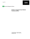
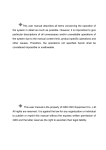
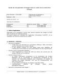
1
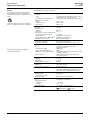
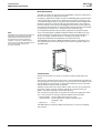
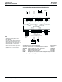
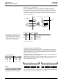
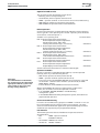
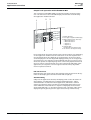
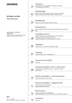
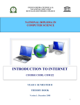
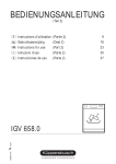
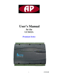
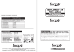
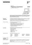
INTEGRAL RSA K21-04.10 1/8 en - 06.2001 Application controllers NRK16/A, NRK16-B/A, (NRK16-T../A, NRK14-T../A, NRK16-WEB/A) Control and interlock devices Application controllers with pre-programmed system-specific application modules. The controllers may be used as stand-alone control and interlock devices for remote process control within a management system Especially suitable for use in small heating, ventilation and air conditioning systems. NRK16/A (with NSA) NRK16-B/A (with NSA) Types Electrical protection The power supply is overload-protected with a PTC thermal element. All DC voltages are electrically isolated from the AC 24 V input. All the inputs are protected against overvoltage (max. AC/DC 45 V). Low-pass filters prevent fluctuations in measurement. All outputs are sustained short-circuit proof. High frequency interference is suppressed by means of filters, or in the case of capacitive interference, discharged via the (earthed) housing or the TE terminal (functional earth). Important: For direction connection of AC 24 V 3-wire peripheral devices, "GND" and "NS" (^) must be connected. NRK16/A Application controller with ten universal inputs1) and two analogue, two digital and two combined outputs NRK16-B/A Like NRK16/A, but with panel for simple local operation NSA Application modules, varying according to country or region, for plugging into base units NRK16-T../A NRK16/A + NITEL integrated communications module for a maximum of three additional devices (see manual NT21) NRK14-T../A Like NRK16-T../A, but without analogue outputs (see manual NT21) NRK16-WEB/A NRK16/A + integrated NIWEB communications module for operation of up to 15 additional devices via the Internet (K1-07.62) Technical data Supply voltage Nominal voltage Max. tolerance Power consumption Without output peripherals With output peripherals Fuse 3 VA Max. 12 VA Thermal element (PTC) Supply voltage for peripheral devices and remote operator terminal Output voltage Output current DC15V ±10%, electrically isolated from AC24V Max. 150 mA Signal inputs 2) Universal inputs 3) Number Use Input impedance 1) The NMID multiplexer enables four digital inputs to be connected to a universal output. (see K21-06.55). The function is integrated by use of a structure macro. 2) When connecting peripheral devices with special input or output signals (e.g. Pt100, phase cut or 3-position signals), the NTIO (NTIOS) single module carrier or an NATU adapter can be used. (See K21-06.50 and K21-06.52). 3) The T1/Ni1000 supply voltage can be disabled at the inputs (see page 5). DIP switches are provided to switch the inputs from T1 to Ni1000 and vice versa. Siemens Building Technologies Remote control input Use Input impedance Signal outputs2) Digital outputs Number Signal Source current Analogue outputs Number Range Source/sink current Extra low voltage (SELV-E) AC 24 V, 50/60 Hz +15 / 10 % 101) Can be structured as T1, Ni1000, DC 0...10 V, digital volt-free, or for connection of NMID Ri (pull-up resistor) = 10 kW to DC +15 V or 100 kW to GND (change-over, see p. 6) Can be structured as T1, Ni1000, DC 0 ... 10 V, min. 1.5 sink, digital volt-free contacts, or NMID Ri (pull-up resistor) = 10 kW to DC +15 V 2 DC 0 / 24 V, 20 / +15 % Max. 50 mA 2 DC 0 ... 10 V Max. 2 mA Technical data continued on page 2 Landis & Staefa Division INTEGRAL RSA K21-04.10 2/8 en - 06.2001 Application controllers Battery In the event of a power failure, data is protected against loss by a replaceable lithium battery (service life approx. 5 ...10 years). Used and faulty batteries must be disposed of in accordance with local regulations. Technical data continued from page 1 Combined outputs Number Type Digital/analogue relationship Remote control output Range Source current Sink current Product data Accuracy Sampling rate Internal Structure Data protection after power failure Structures and parameters 4) Time / date 4) Adjustable values in NRK16-B/A4) NSA application module Connections Connection terminals Cable type and length Communication RS bus 4) Applies to permanently plugged-in application modules Transmission speed Max. cable length (RS bus) NRK16../A connection to RS bus Service terminal DC 0 ... 10 V Max. 10 mA Max. 3 mA Class 0.5 100 ms 0.2 1 s > 10 years Equivalent to battery life Equivalent to battery life EEPROM Type 28C64 2.5 mm2 screw terminals See installation instructions, K21-11.20 Electrically isolated from AC 24 V and signal outputs 9600 baud 2400 m From service socket via 10-core ribbon cable to NARB/A adapter NBRN operator terminal; plugs directly into service socket Weight excluding packaging NRK16/A NRK16-B/A NSA application module 1.15 kg 1.25 kg 0.06 kg Dimensions (W x H x D) NRK16../A NSA application module 162 x 252 x 52 mm 24 x 59 x 49 mm Mounting Safety Product safety Contamination level Electrical safety General ambient conditions Use Temperature range Operation Storage Ambient humidity Conformity Siemens Building Technologies 2 One terminal with a digital and one with an analogue output (see data above) High > 50 %, low < 30 % of analogue signal Snap-mounted on DIN rails or screwed to a flat surface; NRK16-B/A installed in control panel front with the Z402 mounting kit EN 61010-1 2 SELV-E (PELV to IEC 364-4-41) Installed in control panel 5 ... 45 °C 25 ... 70 °C 10 ... 90 %rh, non-condensing This product meets the requirements for marking and is tested Landis & Staefa Division INTEGRAL RSA K21-04.10 3/8 en - 06.2001 Application controllers Brief description The RSA controllers are microprocessor-based DDC controllers comprising a base unit and a plug-in application module. Each plug-in application module contains an EEPROM preprogrammed with a given application chosen from a wide range of heating, ventilation and air conditioning applications. The application modules are held in application libraries in the various national and regional Staefa offices. They can be selected according to the system and plugged into the base unit. The engineering required is thus minimal, and since suitable default settings are provided for setpoints, parameters etc., commissioning is extremely easy. Note: SAPIM (Structure and Parameter Identification Menu) is a programming language developed by Landis & Staefa for the programming of control and interlock modules. It consists of a wide range of basic functions (software modules) which can be combined to create all the structures required. If no suitable standard solution is available, a program for the specific application can be designed in SAPIM and downloaded to the module from a PC. At the same time, the application modules are freely programmable, so that if no suitable standard solution is available, a program can be designed in SAPIM and downloaded to the module from a PC. The EEPROM also holds the NBRN-modifiable setpoints, parameters and time programmes but not the setpoints from the local operator panel of the NRK16-B/A. 92.00157 Construction Essentially, the base unit consists of a metal housing and printed circuit board. The housing comprises a base and a cover, and accommodates the PCB and two-part plug-in connection terminals. These terminals are accessible at the top and bottom of the housing, so that peripheral devices can be connected directly without removing the cover plate. Additional terminals and a 10-pin ribbon cable connector are provided for the power supply, operator terminal and RS bus communication (see page 5, Connection diagram and suitable devices). The cover plate incorporates an aperture for the plug-in application module, a rotary switch for setting the RS bus address and three LEDs: Green (power): Yellow (Tx RS): Red (error) Power supply / basic test (on = OK) Normal operation / RS bus communication (flashing = OK) Error The NRK16-B/A incorporates additional elements for control and display (see page 8). Siemens Building Technologies Landis & Staefa Division INTEGRAL RSA K21-04.10 4/8 en - 06.2001 Application controllers Mounting and dimensions [mm] The base unit can be fixed with four screws directly onto any surface, or snap-mounted on two rails. If mounting rails are used, proceed as follows: 1. Fix the top rail 2. Fit the bottom rail to the base unit and snap-mount the unit onto the top rail 3. Fix the bottom rail The terminal connections are grouped in blocks, making for easy wiring without the need to remove the unit cover. 149 125 243 92.00156 162 52 252 203 92.00158 59 49 24 Caution: The application module is a staticsensitive component. Before inserting or removing the module, the base unit must be disconnected from the power supply. Do not touch the contact pins in the base unit. 15 Opening the controller Caution: Do not touch the PCB. Electronic components can be damaged by electrostatic discharge. Handling the PCB without observing electrostatic precautions will invalidate the warranty. Siemens Building Technologies 1. Ensure that the necessary EMC precautions have been taken. 2. Undo the four cross-head screws between the terminal blocks. 3. Carefully lift off the cover. For the NRK16-B/A: Press the four white plastic clips together with pliers, carefully release the pcb for the display and operating unit, and pull upwards. Observe similar precautions when re-assembling the controller, paying special attention to the fibre optic cables of the LEDs and the extension of switch S100. Landis & Staefa Division INTEGRAL RSA K21-04.10 5/8 en - 06.2001 Application controllers Connection diagram and suitable peripheral devices DC 0 ... 10 V Remote control NMID + - +15 GND T1 digital T1/Ni1000 GND +15 E UI02 UI03 UI04 UI05 F I J UI10 C D UI09 B - + - + - + - + - + 1 2 1 2 1 2 1 2 1 2 UI06 A UI01 - + - + - + - + - + 1 2 1 2 1 2 1 2 1 2 1 2 G H - + + + 1 2 4 6 92.00160en K UI11 UO07 1 2 UI08 1 2 UI07 1 2 SAPIM I/O number UO03 UO04 UO05 UO06 A B C D E F 3 4 3 4 3 4 5 3 4 5 3 5 3 5 - + - + - + + - + + - + - + AC DC 24 V 15 V L N TE (+) (-) GND +15 UO02 Service UO01 SAPIM I/O number 3 = COMMON 4 = DC 0 ... 10 V 5 = digital (DC 0 / 24 V) Notes: 1. The digital outputs (C, D, E and F) are active-type outputs, DC 0 or 24 V (max. 50 mA). 2. Outputs C and D may be used as both digital and analogue outputs. The digital (24 V) signal switchs on when the analogue output is > 5 V, and off when it is < 3 V. 3. Other input and output types may be connected via the NTIO adapter and suitable input or output modules. 3 4 3 5 LN SS NBRN (RS485) AC 24 V 1 2 3 4 ZM100 Relay, 24 VDC Suitable peripheral devices (examples) T1/Ni1000 ZM100/A NTIO NATU NMID Documentation Sensors with T1 or Ni1000 measuring elements Teminal housing for DC 0 ... 10 V valves Single terminal module carrier Adapter for special signals Multiplexer (to increase the number of digital inputs) Various CA2N4591 K21-06.50 K21-06.52 K21-06.55 Room operating units, see page 7 Siemens Building Technologies Landis & Staefa Division INTEGRAL RSA K21-04.10 6/8 en - 06.2001 Application controllers Selection of T1 or Ni1000 sensor Both T1 and Ni1000 sensors can be connected to the RSA application controllers. DIP switch S182 is used to adapt the controller to the required sensor type. External access to this DIP switch is possible after removal of the NSA plug-in application module. The change-over from one sensor type to the other is applied in blocks of eight and three inputs (UI01...UI08 and UI09...UI11 respectively). 00414 Rotary address switch Battery D120 Firmware ON 1 2 S182 T1/Ni1000 switch D140 Application Slot for NSA module ON OFF Settings for switch S182 T1/Ni1000 1) When setting the input parameters in INTEGRAL PLAN, note that the T1 input range should be used for Ni1000 sensors. The controller is adapted to the sensor via the hardware only. The SAPIM software is not affected. 1 2 OFF OFF ON ON Sensor Inputs T1 UI01 to UI08 T1 UI09 to UI16 Ni1000 1) UI01 to UI08 Ni1000 1) UI09 to UI16 The factory setting is T1 Disabling the sensor supply voltage The pull-up resistors (Ri = 10kW) for the T1 and Ni1000 sensor supply voltage can be disabled individually at inputs A (UI101) to J (UI10) with jumpers X310 to X420. This process is required whenever devices are connected which are unable to sink current. Siemens Building Technologies X410 X380 X302 X370 UI06 ... UI10 X301 X420 51068A UI01 ... UI05 X360 Caution The incorrect positioning of jumpers can give rise to offset voltages when active signal transmitters are connected (failure to reach a zero-point). When delivered from the factory, the jumper settings are such that the sensor supply voltage is enabled. To disable the supply, each jumper must be moved one position to the left. X350 Jumper X360 X370 X380 X410 X420 X340 Input F UI06 G UI07 H UI08 I UI09 J UI10 X330 Jumper X310 X320 X330 X340 X350 X320 Input A UI01 B UI02 C UI03 D UI04 E UI05 The jumpers are located on the printed circuit board and cannot be adjusted without opening the controller housing. X310 Inputs and jumpers View of part of the PCB: In this example, apart from X350 and X360 (T1/Ni1000 supply OFF) all the jumpers are shown in their factory-set position. Landis & Staefa Division INTEGRAL RSA K21-04.10 7/8 en - 06.2001 Application controllers Operation and service The controller can be operated by various means: Remotely, from a room operating unit Via the RS bus, with an operator terminal or PC NBRN-.. operator terminal or service PC for service and commissioning NRK16-B/A for simple local operation (see page 8) NRK16-WEB/A for operation with an Internet browser Remote operation Connection terminals K1, K2, K4 and K6 are provided for remote operation from a type KR.. room operating unit. The PB.. operating units should be connected to universal inputs A..J. Suitable room operating units Documentation KRT-1B Room temperature measurement Room temperature setpoint adjustment Mode selection (AUT, ON or OFF) Heating time extension (by 1, 2 or 4 hours) KRT-1L Room temperature measurement Room temperature setpoint adjustment Mode selection (AUT, ON or OFF) Holiday mode extension (by 1, 2 or 3 days) KRU-1 Room temperature measurement Mode selection (AUT, ON or OFF) Timer module with independent time function PBA Room temperature measurement Room temperature setpoint adjustment PBC CA2N1612 CA2N1613 CA2N1614 CA2N1651 Room temperature measurement Room temperature setpoint adjustment Digital display of room temperature CA2N1655 See the relevant documentation for maximum cable lengths Operation via RS bus Important: For communication on the RS bus, the controller must be assigned the appropriate address, by use of the rotary switch on the cover plate. (Factory-setting: Address 1). Since the controller is compatible with the RS bus, it can be operated remotely from any of the following devices: NBE remote operator terminal (see K21-05.18) NBRN-.. operator terminal (see K21-05.10 and 12) From a PC running the INTEGRAL DIALOG service software, connected via the NITEL.. communications module (see K21-07.30) or NARC RS485-RS232 adapter Internet browser, via the NIWEB communications module Where the INTEGRAL RS system is integrated into a higher-level system, the controllers can also be operated as follows: In an INTEGRAL MS1000, MS2000 or TS1500 building management system In the DESIGO INSIGHT building management system, with advanced graphics-based operation Service and commissioning For service and commissioning purposes an NBRN-.. terminal or a PC can be connected directly to the service socket on the controller. The same socket is used to download an application-specific SAPIM program from a suitable PC (not required for pre-programmed modules). User manuals The following user manuals are available for the operator software described above: K23 NBRN.. operator terminals K9 INTEGRAL DIALOG CA12U3290 NIWEB User manual CA1B9110 DESIGO INSIGHT Siemens Building Technologies Landis & Staefa Division INTEGRAL RSA K21-04.10 8/8 en - 06.2001 Application controllers Simple local operation with the NRK16-B/A The cover plate of the NRK16-B/A incorporates facilities for direct operation. The functions of the selectable display and switches are defined by the application module selected. 2 1 3 92.00159 5 4 1 Rocker switches 2 Four-digit 7-segment LED display 3 Display-selector keys, from top: Measured value 1 Measured value 2 Setpoint 1 Setpoint 2 4 Channel LEDs corresponding to selector keys 5 <+> and <> for setpoint entry Each rocker switch has three positions with functions which vary depending on the application module used. The allocation of the two setpoints and two measured values also depends on the application. These four values can be displayed in the four-digit LED display panel by use of the appropriate selector key. The setpoints can be modified with the <+> and <> keys; these also operate as repeating keys when continuously depressed. Each of the four values is associated with one of the red channel LEDs. With some applications, the setpoints can have upper and lower limits, adjustable from an operator terminal. LED function test Depressing the two lower selector keys simultaneously should cause all segments of the display panel and the channel LEDs to light up.. Alarm handling Subject to the application selected, the display panel can also be used to indicate alarms. A code between A1 and A9 can be displayed (A1 A8 for alarms defined in accordance with the application, and A9 for a common alarm). The operation of the controller is not affected by the presence of an alarm. While the measured value or setpoint is displayed, the associated channel LED will flash, i.e. the alarm remains active. The alarm code can be displayed again by pressing the two upper selector keys simultaneously. Siemens Building Technologies Landis & Staefa Division