1
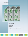
Power Supplies
User Manual
UPS-CONF
Order No.: Configuration and Management Software
UPS-CONF
Power Supplies
User Manual
Configuration and Management Software
UPS-CONF
2012-07-02
Designation: UPS-CONF
Revision:
01
Order No.:
-
This manual is valid for:
Designation
Order No.
UPS-CONF
2320403
104779_en_01
PHOENIX CONTACT
UPS-CONF
Please observe the following notes
In order to ensure the safe use of the product described, you have to read and understand
this manual. The following notes provide information on how to use this manual.
The pictured products do always exemplify the concerned topic.
Target audience for this documentation
The use of products described here solely addresses persons, who are qualified and familiar
with electrical equipment and the appropriate and relevant safety concepts. Please also read
the section titled "Qualified personnel" in the topic titled "Important safety notes (see
page 10)".
Phoenix Contact accepts no liability for erroneous handling or damage to products from
Phoenix Contact or third-party products resulting from disregard of information contained in
this documentation.
Explanation of symbols used and signal words
DANGER
The danger symbol is used to indicate instructions where non-compliance may result in
damage to hardware/software or personal injury (in indirect connection with dangerous
process peripherals).
NOTE
The note symbol precedes notes that must be strictly observed in order to ensure error-free
operation. It also gives you tips and advice on the efficient use of hardware and on software
optimization to save you extra work.
The "Additional Details" symbol indicates cross references (hypertext links or
bibliographical references) which lead to detailed descriptions of a term or additional details
on the context in question.
General terms and conditions of use for technical documentation
Phoenix Contact reserves the right to alter, correct, and/or improve the technical
documentation and the products described in the technical documentation at any time and
without giving prior notice, insofar as this is reasonable for the user. The same applies to any
technical changes that serve the purpose of technical progress. Technical documentation
does not contain any guarantees regarding quality, does not describe any fair marketable
quality, and does not make any claims in terms of quality guarantees or guarantees regarding
suitability for a specific purpose.
PHOENIX CONTACT
104779_en_01
UPS-CONF
The receipt of technical documentation (data sheets, installation instructions, manuals, online
help, etc.) does not constitute any further duty on the part of Phoenix Contact to furnish
information on alterations to products and/or technical documentation. Any other agreement
shall only apply if expressly confirmed in writing by Phoenix Contact.
Please note that the supplied documentation is intended to serve as product-specific
documentation only and that you are responsible for checking the suitability and intended use
of the products in your specific application, in particular with regard to observing the
applicable standards and directives. Although Phoenix Contact makes every effort to ensure
that the information and content is accurate, up-to-date, and refers to the state of the art,
technical inaccuracies and/or printing errors in the information cannot be ruled out. Phoenix
Contact does not offer any guarantees as to the reliability, accuracy or completeness of the
information. All information made available in the technical documentation is supplied without
any accompanying guarantee, whether expressly mentioned, implied or tacitly assumed.
Phoenix Contact accepts no liability or responsibility for errors or omissions in the content of
the technical documentation (data sheets, installation instructions, manuals, online help, etc.).
The aforementioned limitations of liability and exemptions from liability do not apply insofar as
liability must be assumed, e.g., in accordance with product liability law, in cases of
premeditation, gross negligence, on account of loss of life, physical injury or damage to
health, or on account of the violation of important contractual obligations. Claims for damages
for the violation of important contractual obligations are, however, limited to contract-typical,
predictable damages, provided there is no premeditation or gross negligence, or unless
liability is assumed on account of loss of life, physical injury, or damage to health. This ruling
does not imply a change in the burden of proof to the detriment of the user.
Statement of legal authority
This documentation, including all illustrations contained herein, is copyright protected. This
documentation is to be used for its intended purpose only. All other means of usage are
prohibited. Reproduction, translation, and public disclosure, as well as electronic and
photographic archiving and modification, require written consent by Phoenix Contact.
Violators are liable for damages.
Phoenix Contact reserves all rights in the case of patent award or listing of a registered
design. Third-party products are always named without reference to patent rights. The
existence of such rights shall not be excluded.
How to contact us
Internet
104779_en_01
Up-to-date information on Phoenix Contact products and our Terms and Conditions can be
found on the Internet at:
www.phoenixcontact.com
Make sure you always use the latest documentation.
It can be downloaded at:
www.phoenixcontact.net/catalog
PHOENIX CONTACT
UPS-CONF
Subsidiaries
PHOENIX CONTACT
If there are any problems that cannot be solved using the documentation, please contact
your Phoenix Contact subsidiary. Subsidiary contact information is available at:
www.phoenixcontact.com
104779_en_01
Table of Contents
1
Functional overview........................................................................................................
1
2
Software setup ................................................................................................................
3
3
2.1
System requirements................................................................................
4
2.2
Installation................................................................................................
5
2.3
Software settings......................................................................................
5
Hardware overview..........................................................................................................
7
Important safety notes..............................................................................
10
Hardware setup..............................................................................................................
11
3.1
4
5
6
4.1
Buffer time selection................................................................................
12
4.2
Data port..................................................................................................
13
4.3
Connecting the PC....................................................................................
14
Software overview..........................................................................................................
15
5.1
User interface..........................................................................................
15
5.2
Status bar................................................................................................
17
Status - Reported information..........................................................................................
20
System......................................................................................................
20
6.2
Battery......................................................................................................
25
6.3
Battery Advanced....................................................................................
26
6.4
UPS........................................................................................................
27
6.5
UPS Advanced........................................................................................
28
Settings - Defining UPS device parameters....................................................................
29
6.1
7
7.1
Reporting..................................................................................................
31
7.2
Time Setting..............................................................................................
36
7.3
Service......................................................................................................
39
7.4
Advanced................................................................................................
41
8
Monitoring - Statistics and logging..................................................................................
44
9
Stick usage......................................................................................................................
45
10
9.1
Configuration stick usage........................................................................
46
9.2
Service stick usage - service mode..........................................................
47
Application samples......................................................................................................
52
104779_en_01
PHOENIX CONTACT
i
UPS-CONF
11
10.1
Functional test........................................................................................
52
10.2
PC-Mode: PC shutdown and restart......................................................
52
Troubleshooting............................................................................................................
53
11.1
Unexpected status symbols....................................................................
54
11.2
Communication port..............................................................................
56
Index ........................................................................................................................................
57
ii
PHOENIX CONTACT
104779_en_01
Functional overview
1 Functional overview
UPS-CONF is a management software to configure and monitor QUINT-UPS devices, that
come with the IQ technology.
This technology with continuous battery monitoring and intelligent management provides you
with information about the charging state, remaining runtime, and service life of your battery at
all times. Intelligent communication informs you when a situation becomes critical. This
reduces the amount of maintenance involved and increases your system availability.
IQ technology means
•
Intelligent Battery Control: automatically detects the connected battery type and
maximizes the remaining service life of the battery unit via an optimally adapted charging
characteristic.
•
Intelligent Battery Management: continuous status information is shown for
- SOC (State of Charge): current charging state and remaining back-up time of the
battery unit
- SOH (State of Health): remaining life expectancy of the battery unit, provides early
warning for a potential battery unit failure
- SOF (State of Function): determines the current performance of the battery unit.
•
Intelligent Charging: adapts the charging current and thereby ensures the fastest
possible recharging and availability.
•
Intelligent communication: the communication of UPS and PC allows configuration,
extensive signaling and parameterization.
The IQ technology also works without UPS-CONF. With this software you have an easier
monitoring and configurations can be done.
The UPS-CONF software is intended for a PC as well as an IPC (Industrial PC). In this
documentation the term "PC" is used to address both.
The configurable QUINT-UPS device is also referred to as the "UPS" in this documentation.
104779_en_01
PHOENIX CONTACT
1
UPS-CONF
Features supported by the UPS-CONF software
In order to optimally support the IQ technology, UPS-CONF provides the following features:
•
Clear overview about condition of mains, battery, UPS device and connection from PC to
UPS
•
Automatic PC shutdown and restart functionality while the UPS runs in PC-Mode
•
Start of application specific programs for system shutdown
•
Configuration of switching outputs
•
Chronological event logging
•
Setting of customized parameters like the maximum charging current
•
Choice of user interface language in the Software settings (see page 5).
Currently supported languages: English, German
The topic titled Application samples (see page 52) guides through some typical scenarios.
2
PHOENIX CONTACT
104779_en_01
Software setup
2 Software setup
The UPS-CONF software has to be installed on a PC in order to configure and monitor an
UPS system. If the buffered load is a PC, the UPS can be operated in the PC-Mode to
additionally enable the automatic PC shutdown and restart functionality.
To setup the software, the following steps have to be executed:
104779_en_01
1.
Make sure all system requirements (see page 4) for the hardware and software are
met.
2.
Download and install the software (see page 5).
3.
Follow the steps in the hardware setup (see page 11).
4.
Start the software (see page 15).
5.
Become familiar with the software settings (see page 5) supported by the UPS-CONF
software and carry out the required settings.
PHOENIX CONTACT
3
UPS-CONF
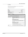
2.1 System requirements
In order to run the UPS-CONF software, your computer must meet the following software and
hardware requirements:
Software requirements
•
Supported operating systems:
- Windows 7, 32bit and 64bit
- Windows Vista SP1
- XP SP3 (requires .NET Framework 3.5 SP1)
•
Supported browser: Internet Explorer version 6 or later
Hardware requirements
CPU
Main memory
4
PHOENIX CONTACT
1 GHz min.
2 GHz recommended
Windows 7
Windows Vista SP1
Pentium III 1GHz min.
2 GHz recommended
Windows XP SP3
1 GB RAM min.
2 GB RAM recommended
Windows 7
Windows Vista SP1
512 MB RAM min.
1 GB RAM recommended
Windows XP SP3
Main memory used by UPS-CONF
max. 96 MB
Hard disk drive (recommended)
Hard disk used by UPS-CONF
850 MB
max. 50 MB
CD-ROM drive
not necessarily needed
Interfaces
1 x USB 2.0
Monitor
VGA, resolution 800 x 600 pixels minimum, 256 colors
Network
Internet connection needed for program download
104779_en_01
Software setup
2.2 Installation
The UPS-CONF configuration and management software can be downloaded free of
charge at www.phoenixcontact.net/catalog.
To install the software, proceed as follows:
1.
Find UPS-CONF at www.phoenixcontact.net/catalog.
2.
Save the UPS-CONF_Setup_v....exe file to the preferred download folder.
3.
Make sure the IFS-USB-DATACABLE is unplugged.
4.
Install UPS-CONF from the selected download folder. Simply follow the screen
instructions.
Read the EULA (End User License Agreement) carefully when it is displayed and agree it
to continue the installation.
5.
After having completed the UPS-CONF installation, connect the UPS device to the PC
(see page 14). If required, select PC-Mode as operating mode (see page 12).
6.
As soon as Windows detects the new USB hardware follow the instructions of the driver
installation.
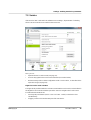
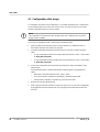
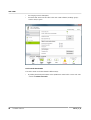
2.3 Software settings
The software settings can be shown by clicking the "Software settings" item in the system
menu.
104779_en_01
PHOENIX CONTACT
5
UPS-CONF
The following settings can be defined:
•
Language of the user interface (English, German)
NOTE
To apply the changed language setting, you have to restart the UPS-CONF
software.
•
Temperature unit (Celsius, Kelvin, Fahrenheit)
•
Communication (USB) port at the PC for the IFS-USB-DATACABLE (COMx)
Normally, the communication port is set automatically by the UPS-CONF software
when connecting the UPS devices. Under normal conditions there is no need to
change this setting. If it has not been set automatically during the software
installation, refer to the section Communication port (see page 56) in the
Troubleshooting topic.
6
PHOENIX CONTACT
•
Enable/disable automatic UPS-CONF startup after PC startup. This option must be
checked if the UPS device shall buffer this PC.
•
Restore the last view after the next software start.
•
Hide or show the advanced views ("Battery Advanced" and "UPS Advanced" in the
"Status" group and "Advanced" in the "Settings" group).
•
An optional password, when parameters are written to the UPS device.
104779_en_01
Hardware overview
3 Hardware overview
Choose your customized solution - for your application.
1.
Choose your power supply.
2.
Choose your UPS unit.
3.
Choose your energy storage.
All Products are available in the e-shop: www.phoenixcontact.net/catalog
104779_en_01
PHOENIX CONTACT
7
UPS-CONF
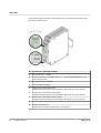
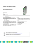
In the next two graphics and their corresponding lists you can see the location of the main
parts of the QUINT DC-UPS.
No. Connections / Operating elements
8
PHOENIX CONTACT
1
DC input 18 V DC ... 30V DC
2
Power storage device connection, 24V DC (+,-, communication between UPS and
power storage device)
3
DC output, 24 V DC, buffered
4
I < IN, fast battery charging
5
Floating relay contact 13/14: alarm
(Related parameter settings are provided in the "Reporting" view (see page 31).)
6
Floating relay contact 23/24: battery mode
(Related parameter settings are provided in the "Reporting" view (see page 31).)
7
Floating relay contact 33/34 : battery charge
(Related parameter settings are provided in the "Reporting" view (see page 31).)
8
24 V DC supply voltage, maximum current limit 0.2 A for the signal contacts 13, 23, 33
9
Remote control (R1, R2).
(Related UPS parameter "Remote Status" (see page 27).)
104779_en_01
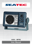
Hardware overview
No. Connections / Operating elements
104779_en_01
10
Bar graph for displaying the current charging state of the power storage device
11
Buffer time setting: unlimited ∞, 1 ... 20 mins., customized (customized default: 0.5),
PC mode (refer to topic Buffer time selection (see page 12)).
12
Red LED: alarm
(Corresponding indicators are displayed in the software's "Status" view (see
page 20).)
13
Yellow LED: battery mode
(Corresponding indicators are displayed in the software's "Status" view (see
page 20).)
14
Plug-in bridge for signal contact supply voltages, pre-installed
15
Remote control plug-in bridge, pre-installed
16
Green LED: Power In OK, mains mode
(Corresponding indicators are displayed in the software's "Status" view (see
page 20).)
17
Data port (see page 13) for data linking to the PC or the use of a memory block
18
Button for use of the memory block
19
LED windows for flat mounting position
20
Universal snap-on foot for DIN rails
21
Accommodation for cable binders
PHOENIX CONTACT
9
UPS-CONF
3.1 Important safety notes
Please observe all the safety notes outlined in this topic when using UPS-CONF together
with the QUINT-UPS device.
Requirements
Knowledge of the following is required:
•
QUINT-UPS system
•
UPS-CONF configuration software
•
Safety regulations in the field of application
Qualified personnel
In the context of using the QUINT-UPS system and the UPS-CONF configuration software
described in this documentation, the following operations may only be carried out by qualified
personnel:
•
Planning, configuration
•
Installation, startup, servicing
•
Maintenance, decommissioning
This documentation is therefore aimed at:
Qualified personnel who plan and design electrical equipment for machines and systems and
are familiar with regulations governing safety in the workplace and accident prevention.
Within the context of the safety notes in this documentation, qualified personnel are persons
who, because of their education, experience and instruction, and their knowledge of relevant
standards, regulations, accident prevention regulations, and service conditions, have been
authorized to carry out any required operations, and who are able to recognize and avoid any
possible dangers.
10
PHOENIX CONTACT
104779_en_01
Hardware setup
4 Hardware setup
NOTE
Before setting up the hardware, install the software (see page 5).
Regarding the communication with the PC and the UPS operation mode, it needs only three
steps to setup the hardware:
1. Set the buffer time at the buffer time potentiometer, as described in the topic Buffer time
selection. (see page 12)
2.
Connect the Data port either with a PC or plug in a configuration stick, as described in the
topic Data port (see page 13).
3.
Connect the load to be supplied by the UPS (see technical datasheet for each QUINTUPS).
NOTE
For further information about the hardware installation (connecting the battery module, etc.)
please refer to the QUINT DC-UPS technical datasheet.
104779_en_01
PHOENIX CONTACT
11
UPS-CONF
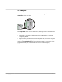
4.1 Buffer time selection
The buffer time potentiometer at the front of the QUINT-UPS has to be switched to the
desired mode with a screwdriver.
The following settings are available:
Operating mode
Description
Custom (default 0.5)
Buffer time can be set to a user-defined value; if no value is set 0.5
minutes is used, as described in the topic Custom Mode (see
page 37).
1, 2, 3, 5, 10, 15, 20
Buffer time 1, 2, 3, 5, 10, 15, 20 minute(s).
PC-Mode
This mode is intended to buffer a PC and to initiate a controlled shutdown in battery mode. The buffer time depends on the "Shutdown
Delay" time and on the "PC-Shutdown" time, as described in the PCMode (see page 38).
∞
No time limit, buffering is continued until the battery is empty (deep
discharge security).
The current set buffer time is shown as "Operation mode" in the status bar (see page 17).
12
PHOENIX CONTACT
104779_en_01
Hardware setup
4.2 Data port
The Data port is located at the front of the UPS. Via this port, configuration and
maintainance of the UPS is done.
The configuration can be done in 2 different ways, depending on what is connected to the
Data port:
•
Connect the PC (see page 14) with the installed UPS-CONF software, if you want to
configure by software.
•
Plug in a memory stick which is declared as configuration stick, if you want to configure
by configuration stick (see page 46).
In order to perfom maintenance tasks (such as changing a battery), a service stick can be
plugged into the Data port, so the UPS switches to service mode (see page 47).
104779_en_01
PHOENIX CONTACT
13
UPS-CONF
4.3 Connecting the PC
A PC has to be connected to the UPS in one of the following cases:
•
You want to configure or monitor the UPS by the UPS-CONF software.
•
You want to display currently set QUINT-UPS parameters or modify them using UPSCONF.
•
You want to initiate a controlled PC shutdown in case of a mains failure and if battery
runs low.
NOTE
First, install the software (see page 5) and then connect the PC afterwards.
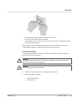
To connect the PC to the QUINT-UPS, proceed as follows:
14
PHOENIX CONTACT
1.
Connect the USB connector of the IFS-USB-DATACABLE to a free USB connector of
your PC. After detecting the device, the used USB port is entered automatically in the
software settings of UPS-CONF.
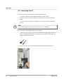
2.
Connect the other side of the IFS-USB-DATACABLE to the Data port of the UPS:
104779_en_01
Software overview
5 Software overview
After installing the UPS-CONF software, the program starts up automatically.
As long as you do not change the related default software setting (see page 5), UPS-CONF
always starts automatically after every PC reboot.
In the following sections you can get an overview about the screen areas of the UPS-CONF
software and you can learn about the different status bar (see page 17) symbols and their
meanings.
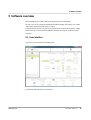
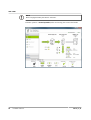
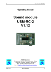
5.1 User interface
The screen layout consists of the following areas:
The following table explains the several areas.
104779_en_01
PHOENIX CONTACT
15
UPS-CONF
16
PHOENIX CONTACT
Area
Description
(1)
Device information:
Here, the type of the connected UPS is displayed. If text has been entered for the
advanced UPS parameter "Place of installation" (see page 41), it is displayed
above the UPS type.
(2)
System menu:
Software settings (see page 5): A mouse click leads to the screen, where various
software settings can be made.
Info: A mouse click shows the contact information of Phoenix Contact.
(3)
Software menu:
The Software menu provides various topic buttons such as status information display, parameter settings or monitoring values. A software menu button is expanded/collapsed by simply clicking it. When a software menu button is expanded the
corresponding navigation items are listed.
(4)
Navigation items:
After clicking a navigation item the corresponding information and parameters are
displayed in the action area.
(5)
Action area:
The content of the action area depends on the currently selected navigation item.
This can be, for example, information, read from the device, or a parameterization
table used for configuring the connected UPS.
(6)
Status bar (see page 17):
Displays the status of all involved components thus providing a quick system overview. The status bar is always visible, also if the navigation and action area
change.
104779_en_01
Software overview
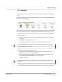
5.2 Status bar
The status bar in the lower part of the screen shows information about the current system
state.
When the power supply is available and the system is online and the battery is fully charged,
the status bar looks like this:
The operation mode in the upper part of the status bar shows the current setting of the buffer
time potentiometer of the UPS, as described in topic Buffer time selection (see page 12).
If it looks different, e.g. Power Source status "UPS off" or no connection to UPS ("Offline"),
verify the following:
•
All UPS components (QUINT-UPS, battery, power supply) are functional and properly
connected.
•
The QUINT-UPS is supplied with 24 V DC.
•
The IFS-USB-DATACABLE is properly connected between QUINT-UPS and PC.
If an alarm is detected or an existing online connection between the PC and the QUINTUPS is interrupted, the UPS-CONF software automatically becomes the active window. The
status is queried every 5 seconds.
If your system status is like described, you can
•
evaluate the UPS system status by displaying the various views contained in the
software menu "Status" (see page 20) and/or
•
start configuring the UPS by modifiying the default parameter settings in the various
views of the software menu "Settings" (see page 29) and/or
•
monitor your system.
In the topic Application samples (see page 52), some typical application scenarios are
described.
The following tables explain the different status symbols that can be visible in the status bar:
104779_en_01
PHOENIX CONTACT
17
UPS-CONF
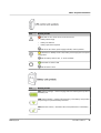
Power Source
Symbol meaning
The status "Mains" is shown, if the power supply is switched on and
available.
The status "Battery" is shown, if the power supply is switched off or not
available.
That means, the battery is discharging.
The status "UPS off" is shown in either case:
•
The UPS is off, because battery mode is finished. The set buffer time
has elapsed.
•
18
PHOENIX CONTACT
The power supply is available, but delivers an invalid output voltage.
Battery
Condition
Symbol meaning
State of charge:
Battery is "Fully charged".
State of charge:
"Charging" is shown, if the battery is currently charging and not
yet fully charged.
State of charge:
The "Discharging" status is shown, if the battery is currently discharging because the system runs in battery mode.
Usually, this status is shown in combination with the power
source status "Battery".
State of charge:
"Uncharged" is shown, if the battery mode is finished and the
battery is empty.
State of health:
The "State of Health" status shows the remaining lifetime of the
battery. The lifetime value is shown below the symbol.
104779_en_01
Software overview
Battery
Condition
Symbol meaning
State of function:
The "State of Function" status shows the current performance
of the battery. This efficiency value is measured in percent and
is shown below the symbol.
During battery charging the battery conditions "State of Charge", "State of
Health" and "State of Function" are shown as "unknown".
Device Status
Symbol meaning
The "UPS OK" status is shown during normal UPS operation, i.e., when
mains is available (battery mode not active) and no other event is currently upcoming.
"Bat.-Mode deactivated" is shown, if the bridge is removed from the terminals R1 and R2.
Refer to the parameter "Remote Status" in the topic UPS (see
page 27).
The "Alarm" status is shown, when a failure or critical situation exists, for
example:
•
battery almost empty
Connection to
UPS
•
battery not detected
•
battery replacement required
Symbol meaning
This status informs about the communication connection between UPSCONF and the QUINT-UPS device. The "Online" status is shown, if the
IFS-USB-DATACABLE is connected.
Normally, this status is automatically entered after connecting the UPS to
the PC via the IFS-USB-DATACABLE.
"Offline" means that no communication connection is established via the
IFS-USB-DATACABLE.
104779_en_01
PHOENIX CONTACT
19
UPS-CONF
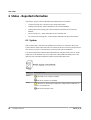
6 Status - Reported information
If the "Status" group is selected, the following navigation items are available:
•
"System (see page 20)": overview on the current system status
•
"Battery (see page 25)": status information for all connected batteries
•
"Battery Advanced (see page 26)": advanced status information for all connected
batteries
•
"UPS (see page 27)" : status information for the connected UPS
•
"UPS Advanced (see page 28)": anvanced status information for the connected UPS
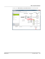
6.1 System
If the "System" item is selected in the software menu "Status", an overview on the current
system status is visible in the action area. The values shown here are read cyclically from the
UPS device, as long as a communication connection to the UPS is established.
The system components and their status information are arranged on the screen as "Power
supply unit" on the left hand side, "UPS control unit" in the middle and "Battery unit" on the
right hand side. The tables explain the symbols corresponding to the units.
Icon
DC OK
Meaning of LEDs
Green LED on: DC output is available.
LED off: DC output is not available.
Boost
Yellow LED on: Boost signal is ON (power supply delivers additional current for a connected load).
LED off: Boost signal is OFF.
20
PHOENIX CONTACT
104779_en_01
Status - Reported information
Icon
Meaning of LEDs
•
Red LED on: UPS alarm due to one of the reasons:
battery almost empty
•
battery not detected
•
battery replacement required
LED off: No UPS alarm, power supply available, normal operation.
Yellow LED on: Battery mode is ON, battery is discharging because power
supply failed.
LED off: Battery mode is OFF, i.e. mains available.
Green LED on: Mains is ON.
LED off: Mains is OFF.
Icon
Meaning of LEDs
SOC (State Of Charge) – current charging state and remaining back-up time of
the battery unit.
SOH (State Of Health) – remaining life expectancy of the battery unit, provides
early warning for a potential battery unit failure.
SOF (State Of Function) – determines the current performance of the battery
unit.
104779_en_01
PHOENIX CONTACT
21
UPS-CONF
NOTE
While charging the battery the status is "unknown".
When the system is in normal operation (online and running), the screen looks like this:
22
PHOENIX CONTACT
104779_en_01
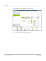
Status - Reported information
When the UPS is offline and has no connection to the PC, the screen looks like this:
104779_en_01
PHOENIX CONTACT
23
UPS-CONF
When the system status shows an alarm, the screen looks like this:
In such case refer to the topic Troubleshooting (see page 53).
24
PHOENIX CONTACT
104779_en_01
Status - Reported information
6.2 Battery
If the "Battery" item is selected in the software menu "Status", status information for all
connected batteries is shown in the action area.
The information is headed by "General information" for all connected batteries, such as
"Number of detected battery units" or "Total nominal capacity".
Individual information for every battery follows.
If several battery units are installed, the data of the individual units can be displayed by
clicking on the battery icons on top of the action area:
The status information in the action area could for instance look similar like this:
Battery parameters
Meaning
Except of some parameters explained here, the status information is self-explanatory, this is why it is not explained in detail.
104779_en_01
Quantity check - Number of installed battery
units?
This value can be set to the amount of batteries, that were built in.
Number of detected battery units
Number of batteries detected by the QUINTUPS.
PHOENIX CONTACT
25
UPS-CONF
Battery parameters
Meaning
Quantity check o.k.
Shows "Yes", if the number of installed battery units complies with the number of detected batteries. Otherwise "No" is displayed.
6.3 Battery Advanced
This navigation item is only available if the "Enable advanced views" checkbox is marked in
the software settings (see page 5).
If the "Battery Advanced" item is selected in the software menu "Status", advanced status
information for all connected batteries is shown in the action area.
In normal operation it looks something like this:
26
PHOENIX CONTACT
104779_en_01
Status - Reported information
6.4 UPS
If the "UPS" item is selected in the software menu "Status", status information for the
connected UPS is shown in the action area.
In normal operation it looks like this:
Parameter
Meaning
Except of some parameters explained here, the status information is self-explanatory, this is why it is not explained in detail.
104779_en_01
Remote Status
Remote control (contact R1, R2)
The module can be switched on and off via a signal to contacts R1 /
R2. Shutdown can take place in mains mode or while battery mode
is active.
Remote shutdown is deactivated
UPS in function (delivery state)
– The "R1" and "R2" terminal points are short circuited (delivery with
plug-in bridge) OR 24 V DC is present at terminal point "R2".
– In the event of a voltage supply failure, the UPS switches over to
battery mode.
Remote shutdown is activated
– The "R1" and "R2" terminal points are not short circuited AND 0 V
is present at terminal point "R2".
– In the event of a voltage supply failure, the UPS does not switch
over to battery mode and the device shuts down.
Selected operation
mode
Shows the operation mode that is set via the buffer time potentiometer, as described in topic Buffer time selection (see page 12).
PHOENIX CONTACT
27
UPS-CONF
6.5 UPS Advanced
This navigation item is only available if the "Enable advanced views" checkbox is marked in
the software settings (see page 5).
If the "UPS Advanced" item is selected in the software menu "Status", advanced status
information for the connected UPS is shown in the action area.
The status information is self-explanatory, this is why it is not explained in detail here.
In normal operation it looks something like this:
28
PHOENIX CONTACT
104779_en_01
Settings - Defining UPS device parameters
7 Settings - Defining UPS device parameters
The navigation items contained in the "Settings" group allow access to the various UPS
device parameters.
Parameter values can be entered in UPS-CONF and written to the device (see page 29)
with only one click of the mouse.
If the software menu "Settings" is selected, the following navigation items are available:
•
Reporting (see page 31): Trigger thresholds, switching outputs for UPS alarm, battery
mode and battery charging as well as Email settings
•
Time Setting (see page 36): Buffer times, (delay) times and programs to execute for PC
shutdown
•
Service (see page 39): Service mode activation and rights granting, declaration of
service stick and configuration stick
•
Advanced (see page 41): Battery charging values, wire sizes, thresholds, signaling
times and others
How to write parameters
In each of the navigation items, different settings can be made in the action area in order to
write it to the UPS.
Beneath settings, that can be made by checking a checkbox or by entering data into an input
box, also numerical or textual values contained in the parameter tables can be changed.
In these parameter tables, changeable parameter values have a white background color.
Read-only values, i.e. the ones that are read from the device for monitoring purposes, are
shown on a gray background.
To enter a new value for a parameter and write it to the UPS, proceed as follows:
104779_en_01
1.
Double-click the line, where the parameter text is located or click the "Write..." button in
the lower right corner.
An input box opens showing the currently set value.
2.
Enter a value into the input box. Make sure that the chosen value is within the allowed
value range and is suitable for your UPS system!
3.
Click the "Write to device" button.
4.
Verify that the new value is now displayed in the parameter table, i.e., has been accepted
by the device.
PHOENIX CONTACT
29
UPS-CONF
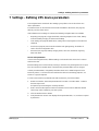
Sample:
Select the "Reporting" navigation item in the "Settings" group and click the "Trigger
Thresholds" tab in the action area.
In this tab, you can set a trigger value, at which battery charging level a "battery low" warning
should be generated (first entry in the tab Trigger Thresholds (see page 31)). The value is
entered as percentage, see below. By default, the trigger is "disabled", i.e. no warning is
reported.
Set the trigger to 20% as follows:
1.
Double-click the marked line, as shown in the figure above or left-click the line and then
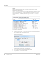
press the "Write..." button in the lower right corner.
The following dialog appears:
Below the text field you can see the allowed input range.
30
PHOENIX CONTACT
2.
Enter 20 in the input box and click the "Write to device" button.
3.
Verify that the new value is shown in the table.
104779_en_01
Settings - Defining UPS device parameters
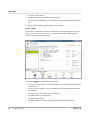
7.1 Reporting
If the "Reporting" item is selected in the software menu "Settings", the tabs "Trigger
Thresholds", "Switching outputs", "Email 1" and "Email 2" are visible in the action area.
Trigger Thresholds
On the "Trigger Thresholds" tab you can define, whether warnings or alarms shall be reported
by the UPS and define the threshold values which must be exceeded in order to trigger a
message.
For each of the following conditions, both a warning and an alarm threshold value can be
defined:
•
Battery is low and the state of charge falls below a certain percentage number.
•
Battery is low and the remaining backup time falls below a defined time.
•
Battery is low and the battery voltage falls below a certain voltage.
•
Battery is at it's end of lifetime and the remaining life time falls below a defined time.
If a warning or alarm is reported, you can define that a switching output must be triggered. For
some of the warnings or alarms an Email to be sent can also be defined.
104779_en_01
PHOENIX CONTACT
31
UPS-CONF
A reported alarm is additionally signaled by the LED at the front of the UPS device as well as
in the status bar of the UPS-CONF software.
By means of warnings and alarms you can implement a two-level detection system:
32
PHOENIX CONTACT
1.
Report a warning, when the first threshold value is exceeded.
Example: battery lifetime is still one year.
2.
Report an alarm, when the second threshold value is exceeded.
Example: remaining lifetime of the battery is only some few months or weeks. Now an
Email is additionally sent to the responsible person to ensure that a new battery is
ordered in time.
104779_en_01
Settings - Defining UPS device parameters
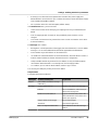
Switching outputs
On the "Switching outputs" tab you can define a QUINT-UPS device output signal to be
switched, when a certain trigger occurs. With such an output signal you can, for example,
control a buzzer, that sounds, if the battery is low or the shutdown has been initiated.
Three different outputs are available to be switched:
•
"Alarm",
•
"Battery Mode"
•
"Battery Charging"
All switching outputs can be triggered inverted, i.e., active low.
The "Battery Mode" and "Battery Charging" output signals can be switched with the following
triggers:
104779_en_01
•
The same triggers as described in section "Trigger Thresholds" for warning and/or alarm,
e.g. triggers that are released by an exceeded or underrun threshold.
•
The quality criteria is no more fulfilled. The IQ-Technology of the QUINT-UPS-IQ is able
to calculate it's own save remaining lifetime for the battery. Based on this calculation, the
quality criteria is evaluated as met or not.
•
The system switches to battery mode.
PHOENIX CONTACT
33
UPS-CONF
•
A shutdown event started.
•
The battery switches to the "Battery Charging" status.
•
For the "Disable external battery charger" trigger, see technical datasheet for the QUINTUPS.
For "Alarm" switching output, no further options can be defined.
Email 1 / Email 2
On the "Email 1" and "Email 2" tabs you can define two separate Email addresses, to which
Emails can be sent if certain events occur. To access the input fields, mark the "enable"
checkbox in the upper part of the screen.
The available triggers to initiate Emails to be sent are:
34
PHOENIX CONTACT
•
A warning occurs as battery is at it's end of lifetime and the remaining life time falls below
a defined time.
•
An alarm occurs as battery is at it's end of lifetime and the remaining life time falls below
a defined time.
•
An alarm occurs as the quality criteria is no more met.
•
The battery switches to battery mode.
•
A shutdown event started.
•
The battery switches to "Battery Charging" status (battery mode deactivated).
104779_en_01
Settings - Defining UPS device parameters
•
A warning occurs because boost operation was activated. The power supply now
delivers BOOST current, which is up to 1.5 times the nominal current of the power supply
(only available with QUINT POWER).
•
The connection to the UPS was interrupted ("Offline" status).
In the Email Server area, you have to enter:
•
"Server name" for the server managing your outgoing mail. Ask your administrator for
details.
•
"Port" for outgoing Emails is usually 25. The predefined port 25, however, can be
changed.
•
"User name" and "Password" of your Email account. In some accounts the "User name"
is the Email address.
The Message area contains:
•
Messagebox: A short explanation of the trigger, that caused the Email, is sent as default
message. You can enter additional text, that will be appended to the default text.
•
"From" textbox: Any Email address can be entered here.
•
"To" textbox: A valid Email address has to be entered here, where the Email is sent to; it
must be an Email address, that exists in the Email server´s configuration.
•
"Subject" textbox: the title of your Email is user-defined; it is only used with the Email
"Test" button. When the Email is successfully sent, click the "Apply" button.
•
"CC" textbox: you can enter an Email address, where a copy is sent to.
You can test your settings by clicking on the "Test" button.
Sample Email:
A sample Email would look like this:
104779_en_01
Email part
Content of Email part
Subject
[UPS CONF: Parameters change
notification]
Message
*** UPS Status Mail ***
Header of the status mail message
Hall 125
Place of installation, refer to the topic
Advanced (see page 41)
QUINT-UPS/24DC/24DC/5
Type of connected UPS, refer to the
device information area in the User interface (see page 15)
Trigger: Battery Mode Trigger
Kind of active trigger
Threshold: -
Threshold (if applicable)
This is an important information.
User defined text from the message
textbox
Explanation
PHOENIX CONTACT
35
UPS-CONF
7.2 Time Setting
If the "Time setting" navigation item is selected in the "Settings" group, the action area
provides various settings for two different UPS operating modes:
36
PHOENIX CONTACT
•
The upper part (above the separation line) specifies the "Custom" mode.
•
In the lower part (below the separation line), four different parameter categories can be
set concerning the PC-Mode.
104779_en_01
Settings - Defining UPS device parameters
Custom mode
NOTE
These settings only apply if the UPS runs in Custom mode. To set this mode, the buffer time
potentiometer located at the device front must be set to "Custom" (refer to topic buffer time
selection (see page 12)).
In Custom mode the buffer time for the battery can be set to a maximum of 1 hour (30
seconds default).
When the power supply was interrupted the load will loose it's power after the user-defined
buffer time has elapsed. The battery will buffer exactly the set buffer time. If no user-defined
time is entered, the buffer time selected by the potentiometer is used.
The set time is displayed in the "Operation Mode" of the status bar. An example with 25
minutes and 45 seconds set, shows the following status bar and operation mode:
104779_en_01
PHOENIX CONTACT
37
UPS-CONF
PC-Mode
NOTE
These settings only apply if the UPS runs in PC-Mode. To set this mode, the buffer time
potentiometer located at the device front must be set to "PC-Mode" (refer to topic buffer
time selection (see page 12).
When the PC-Mode is set, the status bar shows the operation mode "PC-Mode", as shown in
the following screenshot:
In the "PC Mode" setting on the UPS potentiometer, the UPS functionality follows a
chronological sequence that can be parameterized via software, and is thus individually
customized to the respective application.
Parameter
Meaning / Possible settings
1 Shutdown delay
Delay time is calculated automatically from the current remaining
battery life minus the time required by the PC to shutdown. Alternatively, a fixed delay time may be chosen.
2 Program startup
After the delay time has expired it is possible to start a program.
Example: a software starts that gradually backs up system data.
You can test your settings by clicking on the "Test"
button.
38
PHOENIX CONTACT
3 PC shutdown
The time required by the PC/IPC to shut down is set here.
4 PC restart delay
Only if the PC/IPC is shut down, and the mains has returned in the
meantime, the output voltage will be interrupted for the reset time.
The PC/IPC is then automatically restarted.
104779_en_01
Settings - Defining UPS device parameters
7.3 Service
If the "Service" item is selected in the software menu "Settings", all parameters of switching
the UPS to service mode are accessible in the action area.
Here, you can:
•
Operate the UPS in service mode (see page 47).
•
Grant or deny rights for the service mode activation (see section below).
•
Declare memory sticks as either configuration sticks or service sticks, as described in the
topic Stick usage (see page 45).
Rights for service mode activation
The rights for all possible methods to activate or terminate the service mode can be defined in
the "Rights for service mode activation" part of the "Service" navigation item´s action area.
Possible activation methods are:
•
Pressing both push buttons ("Stick -> UPS" and "UPS -> Stick") on the device front
simultaneously.
•
104779_en_01
Plugging a service stick into the Data port of the UPS device.
PHOENIX CONTACT
39
UPS-CONF
•
Clicking the service mode activation button in the "Service" navigation item´s action area
in UPS-CONF.
When allowing a service stick for activating the service mode and disabling the use of the
push buttons at the same time, the stick can be considered as a kind of hardware key: Only
authorized persons who possess a service stick are allowed to switch the device to service
mode. For that purpose, a memory stick must be declared accordingly as described in Stick
usage (see page 45).
For further information please refer to the "Service stick usage - service mode (see
page 47)".
40
PHOENIX CONTACT
104779_en_01
Settings - Defining UPS device parameters
7.4 Advanced
This navigation item is only available if the "Enable advanced views" checkbox is marked in
the Software Settings (see page 5).
The "Advanced" navigation item within the "Settings" group allows to set more specific
parameters. These are in detail:
104779_en_01
Name of parameter:
Sample
value:
Unit:
Explanation:
Place of installation (user defined)
Hall 125
(none) The text entered here is dislayed
in the device information area of
the User interface (see page 15).
Initial charging current
1.36
A
The battery is charged with this
current, when the power supply is
available.
Absorption charging end voltage
28.00
V
An equalizing charge, that increases charging voltage to a higher
value than the nominal capacity
for a short period. This prevents
battery stratification and reduces
sulfation. When the battery is fully
loaded, this voltage is tolerated as
a maximum, before the voltage
level gets a stable end value.
Float charging end voltage
27.60
V
The charger adjusts the end voltage based upon battery temperature. During high temperature periods, the actual battery voltage will
be reduced and during low temperature periods it will be increased.
Temperature compensation
42
mV/K
High ambient temperatures have
a negative impact on the service
life of the battery. Therefore, the
charging voltage should be lower
with higher ambient temperatures.
The adjustable values relate to
one battery cell each.
Wire distance to the battery unit
300
mm
The maximal wire length from the
UPS control unit to the battery
unit.
Wire cross section to the battery
unit
6.0
qmm
The wire cross section from the
UPS control unit to the battery
unit.
PHOENIX CONTACT
41
UPS-CONF
42
PHOENIX CONTACT
Name of parameter:
Sample
value:
Unit:
Explanation:
Fast battery charging
On
(none) Boost mode is allowed or not.
Dynamic backup threshold
Off
(none) This parameter can be defined additionally to the overvoltage and
undervoltage related parameters,
see below. If set to On the voltage
increase or decrease within a certain time period is watched (dynamically). The UPS switches to
battery mode, if the relative increase/decrease is too much.
In contrast the overvoltage and
undervoltage parameters have
static values. They can become
active regardless the dynamic
backup threshold did not trigger,
because the voltage was alright.
Undervoltage backup threshold
19.00
V
When the DC voltage falls under
this threshold (undervoltage), the
system switches to battery mode.
Overvoltage backup threshold
30.00
V
When the DC voltage exceeds
this threshold (overvoltage), the
system switches to battery mode.
Return to mains time
3
seconds
After this time the system returns
to mains, when it is in battery
mode and the power supply is
available again.
Discharging end voltage
19.20
V
The battery voltage may not sink
below this voltage value, otherwise it would be deeply discharged and become defective.
Signaling time after battery low
cutoff
00:10
hh:mm When the battery low status has
arrived, the UPS cuts off and the
status of the power source firstly
switches to "UPS off (see
page 27)". After the time set here
no more power or battery status is
displayed, but only the Connection to UPS (see page 17) is offline.
Signaling time after time cutoff
00:10
hh:mm When the buffer time has elapsed,
the UPS cuts off and the status of
the power source firstly switches
to "UPS off (see page 27)". After
the time set here no more power
or battery status is displayed, but
only the Connection to UPS (see
page 17) is offline.
104779_en_01
Settings - Defining UPS device parameters
Name of parameter:
Sample
value:
Unit:
Explanation:
Battery type (imported item)
"No value (none) The type of battery delivered by
assigned"
the manufacturer. This value is
read by the UPS-CONF software.
Nominal capacity (imported item)
"No value Ah
assigned"
The nominal capacity of the battery delivered by the manufacturer. This value is read by the UPSCONF software.
You can restore the default settings anytime by clicking the "Set factory defaults" button.
You can import / export the list in a .csv file by clicking the button "Import " or "Export".
104779_en_01
PHOENIX CONTACT
43
UPS-CONF
8 Monitoring - Statistics and logging
If the "Monitoring" group is selected, the navigation items "Statistic (user defined)", "Statistic
(system defined)" and "Logging" are available.
The items inform about counted and time measured statistic values and show logged
information.
Statistic (user defined)
The "Statistic (user defined)" navigation item shows counter values which start at a userdefined value. If, for example, batteries have been replaced, you can set the values manually
to "0" in order to start a new logging period. The following values are displayed and can be
reset:
•
Number of battery modes: How often did the UPS already change to battery mode?
•
Total time of battery mode: How long altogether did the UPS stay in battery mode?
•
Number of operation startups: How often was the UPS started?
•
Total operation time: How long altogether did the UPS run?
Statistic (device defined)
The "Statistic (system defined)" navigation item shows counter values which always start from
the value "0" with the initial device installation. Beneath the same values as shown in the
"Statistic (user defined)" navigation item, additional values are displayed:
•
Runtime of the current battery operation: How long does the current battery operation (if
relevent) altready last?
•
Number of battery low cutoffs: How often was the battery completely discharged?
•
Number of all messages: How many warnings and alarms were signaled altogether?
•
Number of remaining lifetime messages: How often was a remaining lifetime signaled?
•
Number of quality criteria messages: How often was signaled, that the quality criteria is
no more met?
•
Number of battery presence messages: How often was a battery unit not detected, e.g.
no fuse plugged or circuit broken?
Logging
The logging is done by the software itself.
The "Logging" navigation item lists events like "Offline", "Online" or "UPS in battery mode"
with date and time stamp. The event colors differ between green and red depending on the
type of event. They are chronologically sorted, the latest uppermost.
You can delete the list by clicking the button "Delete history".
You can export the list in a .csv file by clicking the button "Export".
44
PHOENIX CONTACT
104779_en_01
Stick usage
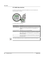
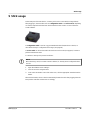
9 Stick usage
At the Data port of the UPS device, a memory stick can be connected (see image below).
After plugging in, the UPS either acts as configuration stick or as service stick, depending
on how the respective stick has been declared before in the "Service" screen of the UPSCONF software.
A configuration stick is used to copy parameterization data from/to the UPS device, as
described in the topic Configuration stick usage (see page 46).
A service stick can be used to switch the device to service mode (see page 47) in order to
perform maintenance tasks.
To declare a memory stick proceed as follows:
NOTE
When declaring a stick, its current content is deleted, i.e. already stored configuration data
are lost.
1.
Open the software menu "Settings".
2.
Click the "Service" navigation item.
3.
In the "Stick declaration" area of the action area, click the appropriate "Start declaration"
button.
After this declaration, the UPS device automatically formats the stick after plugging it into the
Data port the next time and then acts accordingly.
104779_en_01
PHOENIX CONTACT
45
UPS-CONF
9.1 Configuration stick usage
A configuration stick stores UPS configurations, i.e.complete parameter sets. Configurations
can be copied from the UPS to the stick and vice versa. This way, the stick can be used to
transfer configurations from one UPS to another.
NOTE
The configuration stick cannot be used, while the UPS runs in battery mode. The power
supply must be available.
The usage of configuration sticks is explained by the following steps:
1.
Make sure that the used memory stick is already declared as configuration stick as
described in the topic Stick usage (see page 45).
2.
To transfer parameters between the stick and the UPS, execute one of the following
steps:
•
To copy parameters from the stick to the QUINT-UPS push the "Stick -> UPS" button
for more than 2 seconds.
•
3.
46
PHOENIX CONTACT
To copy parameters from the QUINT-UPS to the stick push the "UPS -> Stick" button
for more than 2 seconds.
Connect the configuration stick to the Data port of the UPS under consideration of the
plug direction.
The parameter transfer is started automatically and the progress is signalled by the
LEDs:
•
While data is transferred they flash red - yellow - green.
•
A successful tranfer completion is signalled by a permanent green LED.
•
A faulty tranfer completion is signalled by a permanent red LED.
4.
Remove the stick from the Data port.
5.
After copying a parameter set from an UPS to the stick you can "clone" this configuration
by plugging this stick into another UPS and copying the stored data from the stick into
this UPS.
104779_en_01
Stick usage
9.2 Service stick usage - service mode
The service mode is used, when installation and maintenance work has to be achieved, such
as a battery has to be replaced.
There are several possibilities to switch the UPS to service mode.
The corresponding activation rights have to be granted for service mode activation and
deactivation, as described in the topic Rights for service mode activation (see page 39).
Service mode activation
The service mode cannot be activated, while the QUINT-UPS runs in battery mode. The
power supply must be available.
Depending on the granted activation rights, the service mode can be activated in three
different ways:
•
By holding down both push buttons on the QUINT-UPS named "Stick -> UPS" and "UPS
-> Stick" for at least 6 seconds.
•
By connecting a service stick (see page 45) to the Data port (see page 13) of the UPS.
•
By using the UPS-CONF software as follows:
In the "Settings" group, select the "Service" item, and click the "On / Off" button near the
"Activate service mode" text.
While the service mode is active
•
104779_en_01
the alarm status is activated,
PHOENIX CONTACT
47
UPS-CONF
•
•
the charging current is interrupted,
the status LED "Service mode active" in the UPS-CONF software ("Settings" group /
"Service" item) is green.
Service mode deactivation
The service mode can be deactivated in different ways:
•
48
PHOENIX CONTACT
By holding down both push buttons on the QUINT-UPS named "Stick -> UPS" and "UPS
-> Stick" for at least 6 seconds.
104779_en_01
Stick usage
•
By removing the service stick from the Data port of the UPS.
•
By using the UPS-CONF software as follows:
In the "Settings" group, select the "Service" item, and click the "On / Off" button near the
"Activate service mode" text.
After the service mode is deactivated, the status LED "Service mode active" in the UPSCONF software ("Settings" / "Status") switches back from green to gray.
Service mode operation
To operate the QUINT-UPS in the service mode in order to replace a battery for example,
execute the steps described below.
DANGER
Before activating the service mode read and obey carefully the safety instructions in the
topic Important safety notes (see page 10).
DANGER
Watch polarity when connecting cables!
104779_en_01
1.
Activate the service mode by one of the ways described above.
2.
Replace the battery as follows:.
i.
Open battery housing.
ii.
Remove fuses.
PHOENIX CONTACT
49
UPS-CONF
iii.
Remove cabling.
iv. Change battery.
v.
Connect cabling.
vi. Insert fuses.
vii. Close battery housing.
3.
As soon as the work is finished, the parameters of the new battery have to be read into
the UPS, so it's status information is available. To introduce this battery registration, do
one of the following actions:
•
50
PHOENIX CONTACT
Push one of the push buttons on the QUINT-UPS named "Stick -> UPS" or "UPS ->
Stick" and hold it down for more than 6 seconds.
104779_en_01
Stick usage
or
•
In the "Settings" group of the UPS-CONF software select the "Service" item, locate
the text "Battery replacement ready" and click the "Confirm" button near the text.
The bar graph at the QUINT-UPS flashes, the alarm status is still active.
NOTE
If the service mode has been deactivated by removing the service stick from the
Data port before the battery replacement has been confirmed, it can be confirmed
by the UPS-CONF software. A popup window will remind the user to confirm the
battery replacement.
4.
104779_en_01
Deactivate the service mode as described above.
PHOENIX CONTACT
51
UPS-CONF
10 Application samples
For further information, please take a look at the Software Tutorials or the Quick Start Poster
on www.phoenixcontact.net/catalog. You will find the data if you link to UPS-CONF or
QUINT-UPS.
10.1 Functional test
One of the main functions of the QUINT-UPS is to supply the load, when the mains fails. To
test, if the UPS buffers the load, follow these steps:
1.
Switch off the power supply of the QUINT-UPS.
2.
Check if the QUINT-UPS buffers the load as long as set with the buffer time
potentiometer, refer to Buffer time selection (see page 12).
10.2 PC-Mode: PC shutdown and restart
The IQ technology of the QUINT-UPS is able to control the power supply for a PC. For that
purpose the PC with the UPS-CONF software installed has to be connected to the UPS and
the PC-Mode activated. The PC-Mode enables the automatic PC shutdown and restart
functionality.
To test the PC shutdown and restart functionality in the PC-Mode, proceed as follows:
52
PHOENIX CONTACT
1.
Switch the buffer time potentiometer to "PC-Mode", as described in the topic Buffer time
selection (see page 12).
2.
Connect the UPS device to a USB port of the PC where UPS-CONF is installed (refer to
topic Hardware setup (see page 11)).
3.
Open the software menu "Settings" and click "Time Settings".
4.
Set the parameters for the four different parameter categories, as described in the topic
PC-Mode (see page 38).
5.
Check if the PC shuts down and restarts corresponding to the set parameters. If a
program execution has been set, verify that it is executed.
104779_en_01
Troubleshooting
11 Troubleshooting
If your system does not work properly for any reason, approach the problem in the following
manner:
1.
2.
Check the system status:
•
If the UPS-CONF software is installed, check the status bar (see page 17) and take
a look at the system status.
•
If the UPS-CONF software is not installed, take a look at the front side of the UPS
and check the LEDs (see page 20).
Proceed with the section Unexpected status symbols (see page 54) to find out, what is
wrong.
The section Unexpected status symbols (see page 54) will lead you closer to the solution
of the problem. If there are specific solutions for a single problem, you will be lead to the
section, that describes the problem solving.
104779_en_01
PHOENIX CONTACT
53
UPS-CONF
11.1 Unexpected status symbols
The meaning of status symbols showing an unexpected status is explained in the following
topic.
The first table lists the symbols for the system status, that you can find in the action area and
the second table lists the symbols from the status bar.
System
status
Symbol
Gray: Mains OFF
DC
Gray: DC output not
available
Yellow: Battery mode
Red: UPS alarm
Current situation
and
possible reason
Possible correction
There is no current available. •
Probably the Mains is switch•
ed OFF.
Switch the Mains ON.
The power supply unit cannot •
deliver DC. Either the power
supply is not available or the •
Mains switch is set to OFF.
Switch the Mains ON.
No current is available, thus
the load gets it's power supply from the battery.
•
Switch the Mains ON.
•
Take care that the power supply
is available again.
There may be different reasons:
•
No power supply is
available.
•
Switch the Mains ON.
•
Take care that the power supply
is available again.
•
Check the set thresholds and
compare with the current status.
•
The battery is soon empty.
•
•
The battery has to be re•
placed.
•
The battery cannot be
•
54
PHOENIX CONTACT
There is another battery
problem.
•
A set threshold has been
reached.
Take care that the power supply
is available again.
Solve the battery problem.
Replace the battery.
Check the cables between UPS
and battery.
detected.
•
Take care that the power supply
is available again.
•
Verify that the fuse is installed in
the battery.
104779_en_01
Troubleshooting
Status bar
Symbol
Current situation and
possible reason
Possible correction
The UPS is in battery mode, be- •
cause no power supply is avail•
able.
Take care that the power supply is
available again.
The bridge between the UPS
terminals R1 and R2 is removed. Battery is deactivated
therefore. Refer to the parameter "Remote Status" in the topic
UPS (see page 27).
If you want the battery to be activated
and the battery mode to be introduced,
when the mains fail, bridge the terminals
R1 and R2. Refer to the hardware overview (see page 7).
There is no power supply available. One of these states is ongoing:
•
The UPS is off, because
battery mode is finished.
The set buffer time has
elapsed.
If the UPS is off, because battery mode
is finished, but the battery is funcional:
•
Switch the Mains ON.
•
•
Take care that the power supply is
available again.
If the UPS is off, because battery mode
is finished, and the battery is no more
The power source is not ok, funcional or at it's end of lifetime:
Change the battery.
because input voltage is in •
If the power source is not ok, because
an invalid range.
input voltage is in an invalid range:
•
Check the power supply.
The battery is discharging, because no power supply is available.
•
Switch the Mains ON.
•
Take care that the power supply is
available again.
The battery mode is finished,
because the battery is empty.
•
Take care that the power supply is
available again to reload the battery.
•
Change the battery, if battery lifetime is exhausted.
(see UPS alarm in the table
above)
(see UPS alarm in the table above)
•
•
Connect the UPS and PC via the
IFS-USB-DATACABLE.
•
Check if the communication port is
set, as described in the topic Communication port (see page 56).
•
104779_en_01
Switch the Mains ON.
The connection between
PC and UPS via the IFSUSB-DATACABLE is interrupted.
The communication port is
not set.
PHOENIX CONTACT
55
UPS-CONF
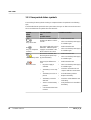
11.2 Communication port
The PC USB communication port for the communication between the UPS and the PC is
automatically set during software installation. In case the communication port has not been
set, the status bar shows the "Connection to UPS: Offline" status.
Although the communication port has not been set, it is detected automatically. Thus you can
set it manually. You just have to select it in the software settings of the system menu.
If you click the combo box near the text "Communication port" the correct port is shown and
you can select it.
56
PHOENIX CONTACT
104779_en_01
Index
A
I
Advanced view setting ............................................ 5
Indication elements ............................................... 15
Automatic software start .......................................... 5
IPC connection ...................................................... 14
B
L
Battery replacement .............................................. 47
Language setting .................................................... 5
Battery status ........................................................ 25
Logging ................................................................. 44
Buffer time potentiometer ...................................... 12
Buffer time setting ................................................. 12
C
Communication port ................................................ 5
Configuration parameters ..................................... 29
Configuration stick ................................................ 46
Custom mode ....................................................... 36
D
Data cable ............................................................. 14
M
Memory stick ......................................................... 46
N
Navigation ............................................................. 15
O
Operating elements ............................................... 15
Overview of system functions ................................. 1
Overview of the user interface ............................... 15
Download web address ........................................... 5
P
E
Parameter settings ................................................ 29
Emails ................................................................... 31
Error conditions ............................................... 53, 54
Password setting ..................................................... 5
PC connection ....................................................... 14
PC-Mode ............................................................... 36
G
Performance characteristics ................................... 1
GUI ........................................................................ 15
Port setting .............................................................. 5
H
Hardware overview ................................................. 7
Preserve last view ................................................... 5
S
Safety information ................................................. 10
104779_en_01
PHOENIX CONTACT
57
Safety requirements .............................................. 10
Sending Emails ..................................................... 31
Service mode ........................................................ 47
Service mode rights .............................................. 39
Service stick .......................................................... 47
Setting advanced parameters ............................... 41
Setting parameters ................................................ 29
Software download ................................................. 5
Software settings .................................................... 5
Statistic values ...................................................... 44
Status bar .............................................................. 17
Status symbols ...................................................... 20
Switching outputs .................................................. 31
Symbols used ......................................................... 4
System requirements .............................................. 4
T
time settings .......................................................... 36
Trigger Thresholds ................................................ 31
U
UPS status ............................................................ 27
User interface ........................................................ 15
W
Writing parameters ................................................ 29
104779_en_01
PHOENIX CONTACT
58