1
Fluid Managment System
LMS-RF Basic System
LMS_RF System Basic System-Zigbee_BA_02_1507
User Manual
Fluid Management System, LMS-RF Basic System
Page ii
July 2015
User Manual
CONTENTS
Introduction . . . . . . . . . . . . . . . . . . . . . . . . . . . . . . . . . . . . . . . . . . . . . . . . . . . . . . . . . . . . . . . . . . . . . . . . . . . . . . . . . . 5
System Overview . . . . . . . . . . . . . . . . . . . . . . . . . . . . . . . . . . . . . . . . . . . . . . . . . . . . . . . . . . . . . . . . . . . . . . . . . . . . 6
System Composition and Dataflow . . . . . . . . . . . . . . . . . . . . . . . . . . . . . . . . . . . . . . . . . . . . . . . . . . . . . . . . . . . . . . . . . 7
Specifications . . . . . . . . . . . . . . . . . . . . . . . . . . . . . . . . . . . . . . . . . . . . . . . . . . . . . . . . . . . . . . . . . . . . . . . . . . . . . . 7
Certification . . . . . . . . . . . . . . . . . . . . . . . . . . . . . . . . . . . . . . . . . . . . . . . . . . . . . . . . . . . . . . . . . . . . . . . . . . . . . . . 8
Wall-Mounting The Keypad . . . . . . . . . . . . . . . . . . . . . . . . . . . . . . . . . . . . . . . . . . . . . . . . . . . . . . . . . . . . . . . . . . . . . . . . . 8
Keypad Description . . . . . . . . . . . . . . . . . . . . . . . . . . . . . . . . . . . . . . . . . . . . . . . . . . . . . . . . . . . . . . . . . . . . . . . . . . 9
Operation Modes . . . . . . . . . . . . . . . . . . . . . . . . . . . . . . . . . . . . . . . . . . . . . . . . . . . . . . . . . . . . . . . . . . . . . . . . . . . 10
Master Keypad . . . . . . . . . . . . . . . . . . . . . . . . . . . . . . . . . . . . . . . . . . . . . . . . . . . . . . . . . . . . . . . . . . . . . . . . . . . . . . . . 11
System Version Screen . . . . . . . . . . . . . . . . . . . . . . . . . . . . . . . . . . . . . . . . . . . . . . . . . . . . . . . . . . . . . . . . . . . . . . . . 11
Settings Overview / Supervisor Menus . . . . . . . . . . . . . . . . . . . . . . . . . . . . . . . . . . . . . . . . . . . . . . . . . . . . . . . . . . . . . 11
Initialization (INI) Menu . . . . . . . . . . . . . . . . . . . . . . . . . . . . . . . . . . . . . . . . . . . . . . . . . . . . . . . . . . . . . . . . . . . . . . . 11
Configuration (CNF) Menu . . . . . . . . . . . . . . . . . . . . . . . . . . . . . . . . . . . . . . . . . . . . . . . . . . . . . . . . . . . . . . . . . . . . . 12
Test Communication (DK) Menu . . . . . . . . . . . . . . . . . . . . . . . . . . . . . . . . . . . . . . . . . . . . . . . . . . . . . . . . . . . . . . . . . 14
Reports (REP) Menu . . . . . . . . . . . . . . . . . . . . . . . . . . . . . . . . . . . . . . . . . . . . . . . . . . . . . . . . . . . . . . . . . . . . . . . . . 15
Radio (RAD) Menu . . . . . . . . . . . . . . . . . . . . . . . . . . . . . . . . . . . . . . . . . . . . . . . . . . . . . . . . . . . . . . . . . . . . . . . . . . 16
Dispense Keypad . . . . . . . . . . . . . . . . . . . . . . . . . . . . . . . . . . . . . . . . . . . . . . . . . . . . . . . . . . . . . . . . . . . . . . . . . . . . . . 18
System Version Screen . . . . . . . . . . . . . . . . . . . . . . . . . . . . . . . . . . . . . . . . . . . . . . . . . . . . . . . . . . . . . . . . . . . . . . . . 18
Settings Overview / Supervisor Menus . . . . . . . . . . . . . . . . . . . . . . . . . . . . . . . . . . . . . . . . . . . . . . . . . . . . . . . . . . . . . 18
Configuration (CNF) Menu . . . . . . . . . . . . . . . . . . . . . . . . . . . . . . . . . . . . . . . . . . . . . . . . . . . . . . . . . . . . . . . . . . . . . 19
Delete Prepared WOs (MET) Menu . . . . . . . . . . . . . . . . . . . . . . . . . . . . . . . . . . . . . . . . . . . . . . . . . . . . . . . . . . . . . . . . 20
Reports (REP) Menu . . . . . . . . . . . . . . . . . . . . . . . . . . . . . . . . . . . . . . . . . . . . . . . . . . . . . . . . . . . . . . . . . . . . . . . . . 21
190 (Internal Ticket Printer) Menu . . . . . . . . . . . . . . . . . . . . . . . . . . . . . . . . . . . . . . . . . . . . . . . . . . . . . . . . . . . . . . . . 21
RF Communication Test (LNK) Menu . . . . . . . . . . . . . . . . . . . . . . . . . . . . . . . . . . . . . . . . . . . . . . . . . . . . . . . . . . . . . . . 22
Radio (RAD) Menu . . . . . . . . . . . . . . . . . . . . . . . . . . . . . . . . . . . . . . . . . . . . . . . . . . . . . . . . . . . . . . . . . . . . . . . . . . 22
Network Connect (CON) Menu . . . . . . . . . . . . . . . . . . . . . . . . . . . . . . . . . . . . . . . . . . . . . . . . . . . . . . . . . . . . . . . . . . 24
System Override (SYS) Menu . . . . . . . . . . . . . . . . . . . . . . . . . . . . . . . . . . . . . . . . . . . . . . . . . . . . . . . . . . . . . . . . . . . . 24
Dispense Keypad Menu Overview . . . . . . . . . . . . . . . . . . . . . . . . . . . . . . . . . . . . . . . . . . . . . . . . . . . . . . . . . . . . . . . . 25
Dispense Process . . . . . . . . . . . . . . . . . . . . . . . . . . . . . . . . . . . . . . . . . . . . . . . . . . . . . . . . . . . . . . . . . . . . . . . . . . . . . . 26
Starting a Work Order . . . . . . . . . . . . . . . . . . . . . . . . . . . . . . . . . . . . . . . . . . . . . . . . . . . . . . . . . . . . . . . . . . . . . . . . 26
RF Meter . . . . . . . . . . . . . . . . . . . . . . . . . . . . . . . . . . . . . . . . . . . . . . . . . . . . . . . . . . . . . . . . . . . . . . . . . . . . . . . . . . . . 28
Key Description . . . . . . . . . . . . . . . . . . . . . . . . . . . . . . . . . . . . . . . . . . . . . . . . . . . . . . . . . . . . . . . . . . . . . . . . . . . . 28
RF Mode (Standard Pre-Selection Mode) . . . . . . . . . . . . . . . . . . . . . . . . . . . . . . . . . . . . . . . . . . . . . . . . . . . . . . . . . . . . 29
AUTO Mode (Autonomous) . . . . . . . . . . . . . . . . . . . . . . . . . . . . . . . . . . . . . . . . . . . . . . . . . . . . . . . . . . . . . . . . . . . . 30
Electrical Override . . . . . . . . . . . . . . . . . . . . . . . . . . . . . . . . . . . . . . . . . . . . . . . . . . . . . . . . . . . . . . . . . . . . . . . . . . 30
Changing the Battery . . . . . . . . . . . . . . . . . . . . . . . . . . . . . . . . . . . . . . . . . . . . . . . . . . . . . . . . . . . . . . . . . . . . . . . . 31
Programming the RF Meter . . . . . . . . . . . . . . . . . . . . . . . . . . . . . . . . . . . . . . . . . . . . . . . . . . . . . . . . . . . . . . . . . . . . 31
July 2015
Page iii
Fluid Management System, LMS-RF Basic System
Installing And Launching The LMS-RF Software . . . . . . . . . . . . . . . . . . . . . . . . . . . . . . . . . . . . . . . . . . . . . . . . . . . . . . . . . . . 32
System Requirements . . . . . . . . . . . . . . . . . . . . . . . . . . . . . . . . . . . . . . . . . . . . . . . . . . . . . . . . . . . . . . . . . . . . . . . . 32
LMS-RF Software Description . . . . . . . . . . . . . . . . . . . . . . . . . . . . . . . . . . . . . . . . . . . . . . . . . . . . . . . . . . . . . . . . . . . 32
Installing the LMS-RF Server . . . . . . . . . . . . . . . . . . . . . . . . . . . . . . . . . . . . . . . . . . . . . . . . . . . . . . . . . . . . . . . . . . . . 33
Installing the LMS-RF Client . . . . . . . . . . . . . . . . . . . . . . . . . . . . . . . . . . . . . . . . . . . . . . . . . . . . . . . . . . . . . . . . . . . . 36
Launching the LMS-RF Software . . . . . . . . . . . . . . . . . . . . . . . . . . . . . . . . . . . . . . . . . . . . . . . . . . . . . . . . . . . . . . . . . 38
LMS-RF System Configuration . . . . . . . . . . . . . . . . . . . . . . . . . . . . . . . . . . . . . . . . . . . . . . . . . . . . . . . . . . . . . . . . . . . 38
Using The LMS-RF Software . . . . . . . . . . . . . . . . . . . . . . . . . . . . . . . . . . . . . . . . . . . . . . . . . . . . . . . . . . . . . . . . . . . . . . . . 39
Setting Up New Users . . . . . . . . . . . . . . . . . . . . . . . . . . . . . . . . . . . . . . . . . . . . . . . . . . . . . . . . . . . . . . . . . . . . . . . . 39
Setting Up Tanks and Fluids . . . . . . . . . . . . . . . . . . . . . . . . . . . . . . . . . . . . . . . . . . . . . . . . . . . . . . . . . . . . . . . . . . . . 40
Setting Up Keypads and Hoses . . . . . . . . . . . . . . . . . . . . . . . . . . . . . . . . . . . . . . . . . . . . . . . . . . . . . . . . . . . . . . . . . . 42
System Settings . . . . . . . . . . . . . . . . . . . . . . . . . . . . . . . . . . . . . . . . . . . . . . . . . . . . . . . . . . . . . . . . . . . . . . . . . . . . 44
Initialize System . . . . . . . . . . . . . . . . . . . . . . . . . . . . . . . . . . . . . . . . . . . . . . . . . . . . . . . . . . . . . . . . . . . . . . . . . . . . . . . 47
Test Comm Option . . . . . . . . . . . . . . . . . . . . . . . . . . . . . . . . . . . . . . . . . . . . . . . . . . . . . . . . . . . . . . . . . . . . . . . . . . 47
Initialize All Option . . . . . . . . . . . . . . . . . . . . . . . . . . . . . . . . . . . . . . . . . . . . . . . . . . . . . . . . . . . . . . . . . . . . . . . . . . 48
Initialize Changes Option . . . . . . . . . . . . . . . . . . . . . . . . . . . . . . . . . . . . . . . . . . . . . . . . . . . . . . . . . . . . . . . . . . . . . . 48
Parts Department User Menu . . . . . . . . . . . . . . . . . . . . . . . . . . . . . . . . . . . . . . . . . . . . . . . . . . . . . . . . . . . . . . . . . . . . . . 49
Creating a New Work Order . . . . . . . . . . . . . . . . . . . . . . . . . . . . . . . . . . . . . . . . . . . . . . . . . . . . . . . . . . . . . . . . . . . . 49
Work Order Reports . . . . . . . . . . . . . . . . . . . . . . . . . . . . . . . . . . . . . . . . . . . . . . . . . . . . . . . . . . . . . . . . . . . . . . . . . 49
Tanks and Fluids . . . . . . . . . . . . . . . . . . . . . . . . . . . . . . . . . . . . . . . . . . . . . . . . . . . . . . . . . . . . . . . . . . . . . . . . . . . . 52
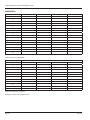
Troubleshooting . . . . . . . . . . . . . . . . . . . . . . . . . . . . . . . . . . . . . . . . . . . . . . . . . . . . . . . . . . . . . . . . . . . . . . . . . . . . . . . 53
Dispense Keypad Error Messages . . . . . . . . . . . . . . . . . . . . . . . . . . . . . . . . . . . . . . . . . . . . . . . . . . . . . . . . . . . . . . . . . 53
Meter Error Codes . . . . . . . . . . . . . . . . . . . . . . . . . . . . . . . . . . . . . . . . . . . . . . . . . . . . . . . . . . . . . . . . . . . . . . . . . . 53
Worksheets . . . . . . . . . . . . . . . . . . . . . . . . . . . . . . . . . . . . . . . . . . . . . . . . . . . . . . . . . . . . . . . . . . . . . . . . . . . . . . . . . . 54
Page iv
July 2015
User Manual
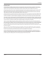
INTRODUCTION
The Badger Meter® Fluid Management System has been designed to control and monitor the consumption and inventory
balances of automotive fluid products with minimal installation and programming costs. Badger Meter has used its years of
expertise in the automated meter reading market to develop a modular control system using RF communications.
The high end system hardware consists of one Master Keypad and at least one Dispense Keypad as well as at least one radio
frequency (RF) electronic preset meter. The Master Keypad handles serial communication between the PC or a host server
(ERP system) and RF communication to the Dispense Keypads in the system. The system verifies the operator’s pin number
and validates the work order number, fluid quantities and the valid hose/meter.
The Master Keypad can communicate with up to 36 Dispense Keypads that can be positioned to support the workflow of the
facility the best way. Each Dispense Keypad can control up to 24 meters, for a total of 250 meters. The system supports up to
16 tanks and 16 fluids as a part of the system configuration. The system supports 250 unique operator IDs and pin numbers.
The system uses direct sequence spread spectrum RF technology to prevent communication problems with other equipment
in the facility. The RF system will look for a clear channel for transmission to insure that there is reliable communications at all
times. Communication distances are typically up to 100 meters, but can go up to 300 meters with unobstructed line-of-sight.
A remote antenna is available for situations where multiple buildings are involved in the installation.
The PC is used to configure the system, maintain system data and enter work orders. The service desk would use the PC to
enter a work order selecting the fluid and quantity required. The PC can stack as many work orders as required, limited only by
the disk storage space of the PC. There is no need to predetermine where the work is going to occur. This allows the flexibility
to service a vehicle at any open bay and select a meter when the work is going to be performed. When the work order is
going to be performed, the service personnel simply enters their pin number, work order and hose that is going to be used at
the Dispense Keypad.
There are a number of system utilization reports by user; fluid type, tank or meters available for the system’s management.
Optionally, the system can be connected with an ERP or DMS system via its RS232 interface. The real-time communication is
based on an open interface protocol (ASCII-code) and can be easily adapted to local conditions.
A unique, patented feature of the system is that the RF meter’s dispense trigger is locked until an authorization from the
keypad is received. After the dispense batch is completed, the user can top off if more fluid is required, the actual dispensed
amount is sent back to the keypad and the meter returns to the locked status. Additionally, the meter can be installed on
portable dolly systems offering control and monitoring of high-cost lubrication products.
July 2015
Page 5
Fluid Management System, LMS-RF Basic System
System Overview
Figure 1: System Overview
Page 6
July 2015
User Manual
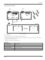
System Composition and Dataflow
Master Keypad
Dispense Keypad
500
1200
Dispenses
Dispenses
printer
RS-232
FMS software
RS-232
Host
RS-232
printer
RS-232
RS-232 Interface
Computer
Database
PC FMS
Figure 2: System Data Flow
The main data streams:
1. The LMS-RF software stores the configuration data into the database.
2. By using the Initialize System menu of the LMS-RF software the configuration data is processed to the Master Keypad and
finally via radio to all Dispense Keypads.
3. The LMS-RF records all dispenses in the database.
Specifications
Power Requirements
120V AC 50/60 Hz
RF Communications
2-way, 2.4…2.5 GHz Direct Sequence Spread Spectrum
RF Network
Self-healing Mesh Network
Operating Temperature
14…140° F (–10…60° C)
Internal Printer
Thermal printer Type FT190 (optional)
External Printer
Epson LX300 or similar (optional)
July 2015
Page 7
Fluid Management System, LMS-RF Basic System
Certification
•
•
•
•
Contains FCC ID: S4GEM35XB
Contains IC: 8735A-EM35XB
FCC CERTIFIED, PART 15, SUB-PART C
CE0681 EC-R&TTE Certified
This device complies with Part 15 of the FCC Rules. Operation is subject to the following two conditions: (1) this device may
not cause harmful interference, and (2) this device must accept any interference received, including interference that may
cause undesired operation.
TO SATISFY FCC RF EXPOSURE REQUIREMENTS FOR MOBILE TRANSMITTING DEVICES, A SEPARATION DISTANCE OF 20
CM OR MORE SHOULD BE MAINTAINED BETWEEN THE ANTENNA OF THIS DEVICE AND PERSONS DURING OPERATION.
TO ENSURE COMPLIANCE, OPERATIONS AT CLOSER DISTANCES THAN THIS ARE NOT RECOMMENDED.
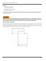
WALL-MOUNTING THE KEYPAD
The keypad should be mounted upright with the antenna pointing upward, near a 120V AC electrical socket, to a structurally
sound wall through the two holes on the top of the keypad casing. Height on the wall should be at eye level. Care should be
taken to avoid mounting behind any steel objects (tool storage cabinets and metal chain linked fences) that may block the RF
communication signal. Care should also be taken to avoid direct, significant heat sources.
7-5/8”
3-3/16”
7-3/8”
Figure 3: Mounting Dimensions for Keypad
Page 8
July 2015
User Manual
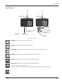
Keypad Description
Dispense Keypad
Master Keypad
Interface to FMS
software (RS232)
External printer port (RS-232)/
Bar Code Reader
Internal printer
Type FT190
Power supply
120V AC 50/60 Hz
Power supply
120V AC 50/60 Hz
External printer
(RS232)
Host link
(RS232)
Figure 4: Keypad description
The SCROLL key selects options on the active display.
The HOME key returns the display to the default screen.
The BACKSPACE key deletes one character to the left of the cursor each time it is pressed.
The ENTER key completes the current action then displays the next screen.
The SPACE key adds a blank space to the right of the data just entered.
to
July 2015
The Alphanumeric keys enter numbers and alpha characters (letters).
• To enter a number, press and release a key.
• To enter a letter, press and hold the key until the letter you want displays, then release the key.
Page 9
Fluid Management System, LMS-RF Basic System
Operation Modes
The configuration of the system is generally done by using the PC-based LMS-RF Software. Only some special functions like
the operation modes are set at the Master Keypad.
RF System with PC Operation Mode
In this mode the PC is used to configure the system entities and install the network. The PC will be used to enter work orders
for processing and provide the queuing for future processing. When an operator processes a work order the PC will validate
the work order number and provide the fluid and amount to be dispensed. The results of the dispense will then be stored on
the PC.
RF System with Host Operation Mode
In this mode the PC is used to configure the system entities and install the network.
The host will be used to enter work orders for processing and provide the queuing for future processing. It will also store
the dispense results that have been completed. Dispense results can be additionally stored on the PC. When an operator
processes a work order the host will validate the work order number and provide the fluid and amount to be dispensed.
Standalone Mode
Work orders will not be validated; each entered work order will be accepted by the system. Data will be stored in the Master
Keypad’s memory.
NNOTE: Each meter can only be associated to one Dispense Keypad. Only dispense and keypad supervisors can access each
of the Dispense Keypads.
Page 10
July 2015
User Manual
MASTER KEYPAD
The Master Keypad acts as the communications director for the RF communications. It handles all communications between
the Dispense Keypads and the PC or Host. There are no operator menus associated with the Master Keypad—only supervisor
menus for setting up the system or creating reports.
The remainder of this document shows only the actual display, not the entire keypad.
To gain access to the supervisor menus, the supervisor PIN has to be entered. The default PIN is 0001 at initial power-up.
System Version Screen
16aug2012 08:35
V3.00
The standard screen shows the system date and software version
number. The display will alternate between the standard screen and
the Enter Pin Number screen. The Enter Pin Number screen is used to
access the supervisor menus.
16aug2012 08:35
V3.00
N
NNOTE: An "N" displayed in the lower left-hand corner of the system
version screen indicates a Radio Network error. See “Radio
Status” on page 17 to check the source of the error.
Settings Overview / Supervisor Menus
The following changes can only be made at the Master Keypad in the setup mode. All other settings can be changed by using
the LMS-RF software.
Enter PIN Number
Enter Pin No.
- - - -
To access the setup mode:
Enter the supervisor PIN number and press ENTER.
The default PIN is 0001 at initial power-up.
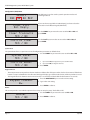
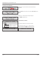
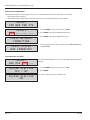
Initialization (INI) Menu
Select
INI CNF DK REP
The INI menu is used to set the system’s date and time.
Set System Time
Enter time
--:--
To change or set the system time:
1. Select the INI menu and press ENTER.
2. Use the numeric keys to set a 24-hour military time of day.
3. Press ENTER to save the setting and advance.
Set System Date
Enter date
--/jan/---Enter date
19/aug/2012
To change or set the system date:
1. Use the numeric keys to enter the two-digit day.
The cursor automatically moves to the month.
2. Press the SCROLL key to select a month.
3. Use the numeric keys to enter the four-digit year.
4. Press ENTER to save the setting.
July 2015
Page 11
Fluid Management System, LMS-RF Basic System
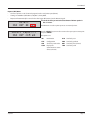
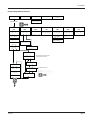
Configuration (CNF) Menu
Select
INI CNF DK REP
Order List
Not Empty
Clear Transacts
YES / NO
Confirm Clear
YES / NO
The CNF menu is used to set the system’s operation modes and
archiving methods.
If you see the message “Order List Not Empty," you have to clear the
transactions in the Master Keypad (CNF Menu).
Use the SCROLL key to move the cursor to either YES or NO and
press ENTER.
Use the Scroll key to move the cursor to either YES or NO and
press ENTER.
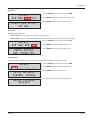
System Reset
The System Reset allows a supervisor to reset all configuration parameters to default values.
System Reset
YES / NO
Confirm Reset
YES / NO
1. Use the SCROLL key to move the cursor to either YES or NO.
a.
b.
If you select YES, the keypad asks you to Confirm Reset.
If you select NO, the keypad advances.
3. Press ENTER.
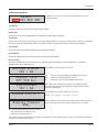
Keypad Timeout
•
•
Timeout parameter corresponds to the time it takes to validate after all dispense order data has been entered. If the Enter
button is not pressed within the time allocated, the keypad display goes back to initial menu and the input data is erased.
The Keypad Timeout is between zero to 255 seconds (0 = no timeout) and the default for this feature is 10 seconds.
Keypad timeout
16-
1. Press the BACKSPACE key to erase the current setting.
2. Type in the new setting.
3. Press ENTER to advance.
Buzzer
This screen provides a user with the option to have a beep on every key entry. The default is YES.
Buzzer
YES / NO
Page 12
1. Use the SCROLL key to move the cursor to YES or NO.
2. Press ENTER to advance.
July 2015
User Manual
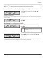
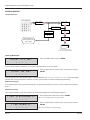
Work Order Validation
WO validation is used to define if a work order shall be validated by the system before processing it.
Host Validation (Host Operation Mode)
In this mode the work order number will be sent to the ERP (DMS) system. Only after validation from the system the meter will
unlock. Afterwards the dispense data will be sent to the ERP system.
WO Valid. HOST
YES / NO
1. Use the Scroll key to move the cursor to either YES or NO.
2. Press ENTER.
PC Validation (PC Operation Mode)
In this mode the work order number will be sent to the PC (LMS-RF Software). Only after validation from the PC will the order
number is accepted.
WO Valid. PC
YES / NO
1. Use the SCROLL key to move the cursor to either YES or NO.
2. Press ENTER.
WO Archive (Printout or Storing of the Work Order /Dispense Results)
WO archived
None Mem Print
1. Use the SCROLL key to move the cursor to your selection.
2. Press ENTER.
Mem Data stored in an optional memory module.
Print After each dispense, the data will be printed out on the
external printer.
Each line displays one dispense.
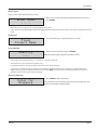
Archive on PC (Archive of the Work Orders/Dispenses)
Archive on PC ?
YES / NO
1. Use the SCROLL key to move the cursor to either YES or NO.
2. Press ENTER.
All dispense results are stored on the PC (LMS-RF Software). If the PC is currently not available, the data will be tagged as “not
sent” in the memory of the master. The data will be sent as soon as the PC is connected again.
July 2015
Page 13
Fluid Management System, LMS-RF Basic System
Test Communication (DK) Menu
Select
INI CNF DK REP
Test All DKs
YES / NO
The DK menu is used to check the communication between
all keypads.
Use the Scroll key to move the cursor to either YES or NO and press
ENTER.
Three Dispense Keypads are set up in the following example. Each "–" (dash) stands for a Dispense Keypad.
Start DKpd Test
Press Enter
Results 1-16
OOK-------------
Press ENTER to begin the test.
N=Network Error, T=Timeout
Three Dispense Keypads are set up in this example.
Keypad 3 - No Connection
Keypad 2 - Detected
Keypad 3 - Detected
Results 17-32
----------------
Page 14
In the following examples, each "–" (dash) stands for a
Dispense Keypad. Press ENTER to display these results.
Results 33-36
----
July 2015
User Manual
Reports (REP) Menu
•
•
•
Connect a printer or a PC (Terminal program) to the serial printer port (RS232).
Settings are 9600 Baud, Data Bits 8, Stop Bits 1, Parity ODD.
Reports will automatically be stored in the data logger (RF memory) at the Master Keypad.
Select
INI CNF DK REP
Select Report->
INI CNF COM WO
July 2015
To use this feature you must the select External Printer option in
the CNF menu.
The REP menu is used to print reports to an external printer.
Use the SCROLL key to move the cursor to the report you want to print
and press ENTER.
The options are:
INI
Initialization
USR
Sort list by user
CNF
Configuration
PRO
Sort list by product
WO
Sort list by work order
HOS
Sort list by hose (meter)
COM
Display the
communication status
of hoses/meters.
TNK
Sort list by tank
Page 15
Fluid Management System, LMS-RF Basic System
Radio (RAD) Menu
The RAD menu screens are:
• Address (ADR) toggles the display between the Radio Address and the Radio Prefix screens.
• Network (NWK) allows you to select the Radio Network.
• Power (PWR) displays the radio’s transmit (Tx) output power.
• Status (STA) displays the Radio Network Status.
• Change Channel (CHA) allows you to select a different RF channel.
Select
INI CNF MET REP
Select
RAD ... ... ...
Select
ADR NWK PWR STA
1. Use the SCROLL key to move the cursor to REP.
2. Press SCROLL two more times to move the cursor to the RAD
selection.
3. Press ENTER to display the RAD screen.
4. Use the SCROLL key to move the cursor to the information you
want to display.
5. Press HOME to go back to the default screens.
Radio Address/Radio Prefix
Once you select ADR, you can use the Scroll key to toggle between the Radio Address and the Radio Prefix screens.
Select
ADR NWK PWR STA
RADIO PREFIX
00:0D:6F:00
RADIO ADDRESS
01:80:A5:63
1. Use the SCROLL key to move the cursor to ADR.
2. Press SCROLL again to display the Radio Prefix screen.
3. Press ENTER to display the Radio Address screen.
4. Press ENTER to return to the selection screen.
Radio Network
The Radio Network default is zero. You need to change this setting only if you have multiple RF LMS-RF systems. All
RF Meter/Hose Radio Network settings must match the Master Keypad and Dispense Keypad settings.
Select
ADR NWK PWR STA
RADIO NETWORK
0--
Page 16
1. Use the SCROLL key to move the cursor to NWK.
2. Press ENTER to display the Radio Network screen.
3. Press ENTER to return to the selection screen.
July 2015
User Manual
Radio Power
Select
ADR NWK PWR STA
RADIO PWR LEVEL
20 dBm
1. Use the SCROLL key to move the cursor to PWR.
2. Press ENTER to display the Radio Power Level screen.
3. Press ENTER to return to the selection screen.
Radio Status
The Radio Status options are:
• NWK CONNECTED – The network is connected and operational.
• SERIAL ERROR – There is a radio communication error on the serial bus between the keypad and the radio.
Select
ADR NWK PWR STA
RADIO STATUS
NWK CONNECTED
1. Use the SCROLL key to move the cursor to STA.
2. Press ENTER to display the Radio Status screen.
3. Press ENTER to return to the selection screen.
Change Channel
The Change Channel option is used to select a different RF channel if the current channel is noisy.
Select
CHA ... ... ...
RADIO NETWORK
CHANNEL CHANGE
RADIO COMMAND
SUCCESS
July 2015
1. Use the SCROLL key to move the cursor to CHA.
2. Press ENTER to display the Radio Network screen.
3. Press ENTER to select a new channel.
4. The screen displays the radio command status.
Page 17
Fluid Management System, LMS-RF Basic System
DISPENSE KEYPAD
The Dispense Keypads are responsible for the communication with the RF meters. The user starts a work order from the
keypad. After the dispense operation has been completed the keypad will receive the actual amount dispensed from the
meter. The Dispense Keypad then sends the dispense results to the Master Keypad.
The system can handle up to 36 Dispense Keypads. Up to 24 meters can be assigned to each keypad but each meter can only
be assigned to one Dispense Keypad.
System Version Screen
V3.00 2.4 GHz
N
M
O
V3.00 2.4 GHz
The standard screen shows the system software version number. The
display will alternate between the standard screen and the Enter Pin
Number screen. The Enter Pin Number screen is used to access the
supervisor menus.
NNOTE: An "N" displayed in the lower left-hand corner of the system
version screen indicates a Radio Network error. See “Radio
Status” on page 23 to check the source of the error.
V3.00 2.4 GHz
NNOTE: An "M" displayed in the lower left-hand corner of the system
version screen indicates that the Dispense Keypad has joined
an RF network, but cannot currently contact the Master
Keypad for WO authorization.
V3.00 2.4 GHz
NNOTE: An "O" displayed in the lower left-hand corner of the system
version screen indicates that the Dispense Keypad is in System
Override mode. See “System Override (SYS) Menu” on page 24
for details.
Enter Pin No.
- - - -
Enter a user PIN to start a work order or the supervisor PIN to enter the
supervisor menus (the default PIN is 0001).
Settings Overview / Supervisor Menus
The following configuration options are only available at the Dispense Keypad.
The default value for the Supervisor PIN is 0001.
Page 18
July 2015
User Manual
Configuration (CNF) Menu
Select
CNF MET REP 190
The CNF menu is used to set the system’s operation modes and
archiving methods.
System Reset
Resets the system parameters to the original factory settings.
Mileage Type
Defines the unit for the Free Alphanumeric field (Defined in Global Keypad Settings)
Top Off Timer
Specifies the amount of time, how long user can make additional dispenses. Is the time allowed after a dispense is completed
before the meter will automatically lockout and send the dispense results back. (Defined in Global Keypad Setting)
Internal Printer
Enables the internal ticket printer. (Defined in Global Keypad Settings)
External Printer
Enables the external report printer port. (Defined in Global Keypad Settings)
Barcode Scanner
This menu will define the external Printer port as a Barcode Reader Port (RS232), if the External Printer is enabled the
Barcode Scanner menu will disappear.
Barcode Scanner
YES / NO
Scanner Lock
OFF PIN ALL
PIN Encoded
YES / NO
Encode Prefix #
Display Timeout
100_
Select YES to enable the Barcode Scanner.
OFF
PIN
All
Data can be entered with Keypad & Barcode Scanner
PIN has to entered by Barcode Scanner
All data has to be entered with Barcode Scanner
When PIN or All is selected you can choose an additional prefix
character. The prefix character will not be displayed and cannot be
entered on the keypad.
Choose the desired prefix, available characters are:
# $ % &´ ( ) * +, - Space / : ; < = > ? @ [ ] ^ ` { | } ! ” #
Defines the time, how long the scanned information will be shown on
the display in units of 1/10 second. For example, 100 = 1 second.
We recommend the following barcode scanners:
•
Wall mounted: Datalogic Magellan 1000i
•
Handheld: Datalogic Gryphon 4100
The scanner has to be programmed according to our specification. Null modem adapter has to be used between the keypad
serial port and the barcode scanner.
July 2015
Page 19
Fluid Management System, LMS-RF Basic System
Buzzer
The buzzer beeps each time you press a button. You can turn off the sound. See Global Keypad Settings.
Auto Override
Activates the system Auto Override feature in all keypads so users can dispense WOs when the Master Keypad is not
operational. No supervisor intervention is required. Available with v3.X firmware only. After five failed MK communication
attempts, the Auto Override feature automatically puts the keypad in system override mode.
Auto Override
YES / NO
1. Use the SCROLL key to move the cursor to either YES or NO.
2. Press ENTER.
Batch Quantity Locked
Batch Qty Locked
YES / NO
With the Batch Quantity Locked, you cannot change the batch quantity
that was entered on the work order. If the work order has a batch
quantity of zero, you can change the batch quantity.
Hose ID First
Hose ID First
YES / NO
Used for HOST communication option only.
Selected product ID will be sent to the HOST.
Delete Prepared WOs (MET) Menu
Work orders that have been entered at a keypad are stored until they are picked up by the appropriate meter (by pressing
RESET at the meter). Meanwhile, the meter is locked for other dispenses.
Select
CNF MET REP 190
Init All Hoses
YES / NO
Reset All Hoses
Press Enter
Page 20
The MET menu is used to delete prepared work orders and release the
meter for new work orders.
1. Use the Scroll key to move the cursor to either YES or NO.
2. Press ENTER.
3. Press ENTER.
July 2015
User Manual
Reports (REP) Menu
•
•
•
Connect a printer or a PC (Terminal program) to the serial printer port (RS232).
Settings are 9600 Baud, Data Bits 8, Stop Bits 1, Parity ODD.
Reports are automatically stored in the data logger (RF-memory) at the Master Keypad.
Select
CNF MET REP 190
To use this feature, you must the select External Printer option in
the CNF menu.
The REP menu is used to print reports from an external printer.
Select Report->
INI CNF MET WO
Use the SCROLL key to move the cursor to the report you want to print
and press ENTER.
The options are:
Select Report->
USR PRO HOS TNK
INI
CNF
MET
WO
Initialization
Configuration
Sort list by meter
Sort list by work order
USR
PRO
HOS
TNK
Sort list by user
Sort list by product
Sort list by hose (meter)
Sort list by tank
190 (Internal Ticket Printer) Menu
Use this menu to print the configuration and status reports from the internal printer FT 190 (optional).
Select
CNF MET REP 190
Select Report->
INI CNF MET WO
July 2015
To use this feature, you must the select Internal Printer option in
the CNF menu.
The 190 menu is used to print reports from an internal printer.
Use the SCROLL key to move the cursor to the report you want to print
and press ENTER.
The options are:
INI
Initialization
MET
Sort list by meter
CNF
Configuration
WO
Sort list by work order
Page 21
Fluid Management System, LMS-RF Basic System
RF Communication Test (LNK) Menu
Select
LNK RAD SYS ...
The LNK Menu is used to check the quality of the RF communication
between the Master and Dispense Keypads.
The test performs a number of test communications and measures the quantity of lost transmissions. The Link Quality 10 is the
maximum you can achieve.
Start Link Test
Press Enter
Test in
Progress
Test Complete
Link Quality: 10
Enter to Cancel
Press Enter
Radio (RAD) Menu
The RAD menu screens are:
• Address (ADR) toggles the display between the Radio Address and the Radio Prefix screens.
• Network (NWK) allows you to select the Radio Network.
• Power (PWR) displays the radio’s transmit (Tx) output power.
• Status (STA) displays the Radio Network Status.
• Network Connect (CON) connects the keypad to a new Master Keypad network.
Select
INI CNF MET REP
Select
LNK RAD SYS ...
Select
ADR NWK PWR STA
1. Use the SCROLL key to move the cursor to REP.
2. Press SCROLL two more times to move the cursor to the RAD
selection.
3. Press ENTER to display the RAD screen.
4. Use the SCROLL key to move the cursor to the information you
want to display.
5. Press HOME to go back to the default screens.
Radio Address/Radio Prefix
Once you select ADR, you can use the Scroll key to toggle between the Radio Address and the Radio Prefix screens.
Select
ADR NWK PWR STA
RADIO PREFIX
00:0D:6F:00
Page 22
1. Use the SCROLL key to move the cursor to ADR.
2. Press SCROLL again to display the Radio Prefix screen.
July 2015
User Manual
RADIO ADDRESS
01:80:A5:63
3. Press ENTER to display the Radio Address screen.
4. Press ENTER to return to the selection screen.
Radio Network
The Radio Network default is zero. You need to change this setting only if you have multiple RF LMS-RF systems. All
RF Meter/Hose Radio Network settings must match the Master Keypad and Dispense Keypad settings.
Select
ADR NWK PWR STA
RADIO NETWORK
0--
1. Use the SCROLL key to move the cursor to NWK.
2. Press ENTER to display the Radio Network screen.
3. Press ENTER to return to the selection screen.
Radio Power
Select
ADR NWK PWR STA
RADIO PWR LEVEL
20 dBm
1. Use the SCROLL key to move the cursor to PWR.
2. Press ENTER to display the Radio Power Level screen.
3. Press ENTER to return to the selection screen.
Radio Status
The Radio Status options are:
• NWK CONNECTED – The network is connected and operational.
• SERIAL ERROR – There is a radio communication error on the serial bus between the keypad and the radio.
• NWK DOWN – There is no network within the range of the Dispense Keypad.
• NWK LOST – The network connection is currently unavailable.
Select
ADR NWK PWR STA
RADIO STATUS
NWK CONNECTED
July 2015
1. Use the SCROLL key to move the cursor to STA.
2. Press ENTER to display the Radio Status screen.
3. Press ENTER to return to the selection screen.
Page 23
Fluid Management System, LMS-RF Basic System
Network Connect (CON) Menu
The Network Connect forces the keypad to connect to a new Master Keypad network. This option is used when:
• Replacing the Master Keypad.
• Moving the Dispense Keypad if the Dispense Keypad does not automatically find the new network.
Select
ADR NWK PWR STA
Select
CON ... ... ...
RADIO NETWORK
CONNECTING
RADIO STATUS
NWK CONNECTED
1. Use the SCROLL key to move the cursor to CON.
2. Press ENTER to display the Radio Network screen.
3. Press ENTER to display the Radio Status screen.
4. The screen displays the radio connection status (NWK CONNECTED
or NWK DOWN).
System Override (SYS) Menu
Select
LNK RAD SYS ...
System Override
YES / NO
System Override
ON
Page 24
The System Override Menu is used to override verification of the Master
Keypad.
1. Use the SCROLL key to move the cursor to YES.
2. Press ENTER.
The screen verifies that System Override is On.
July 2015
User Manual
Dispense Keypad Menu Overview
Enter PIN No.
----
Enter WO No.
---------------
Enter Hose
---
Quantity
----
Enter For
Dispense
Fluid
Product Name
Supervisor 0001
0000
CNF
MET
REP
190
LNK
RAD
SYS
System Reset
YES / NO
Init All Hoses
YES / NO
Select Report >
INI CNF ... WO
Select
FLU HOS
INI
CNF MET
TNK WO
USE
Start Link Test
Press Enter
Select
ADR NET PWR STA
System Override
YES / NO
Test in
Progress
>>>>>
Test Complete
Link Quality:
XX
Select
CON ... ... ...
Mileage Type
KM / Miles
Topoff Timer
0---Internal
Printer
YES / NO
External
Printer
YES / NO
Reset All Hoses
Press Enter
Hose RESET
Hose No --Barcode Scanner
YES / NO
Sanner Locked
OFF
Buzzer
YES / NO
Auto Override
YES / NO
Batch Qty
Locked
Hose
YESID/ First
NO
YES / NO
July 2015
PIN
Barcode menu disappears if the
External Printer is on YES.
All
Pin Encoded
YES / NO
Encode Prefix #
Display Timeout
Available characters:
# $ % &´ ( ) * + , Space / : ; < = > ? @ [
] ^
` { | } ! ” #
90-
Page 25
Fluid Management System, LMS-RF Basic System
DISPENSE PROCESS
Schematic Overview
Enter PIN No.
----
Enter WO No.
123A2
---------
Enter Hose
02-
Hos e ID First
YES / NO
Quantity
3.0-
WO Valid Host
YES / NO
WO Valid. PC
YES / NO
Enter for
Dispense
External validation
By FMS Software (PC)
Or Host (DMS)
Order stored in Dispense Keypad
until the meter RESET button is pressed.
Starting a Work Order
Enter Pin No.
- - - -
1. Enter your PIN number and press ENTER.
To start a work order, the mechanics or users must enter their PIN to access the system.
Enter WO No.
- - - -
2. Enter an alphanumeric number (max. 16 characters) and press
ENTER.
In the operation modes WO Validation HOST or WO Validation PC (see “Work Order Validation” on page 13) the entered WO
number will be compared with the numbers set in the system, which are defined in Global Keypad Settings.
Alphanumeric Keypad
To change from the numeric to the letter keypad, press the equivalent key for at least 3 seconds until the desired letter is
shown.
Additional Free Fields
These optional fields are only shown if they have been enabled (defined in Global Keypad Settings).
Free Alphanumeric
- - - Free Numeric
- - - Page 26
3. Enter alphanumeric characters and press ENTER.
Can be used, for example, for the licences plate number.
4. Enter an alphanumeric number (max. 16 characters) and press
ENTER.
Can be used, for example, for the actual mileage.
July 2015
User Manual
Meter Selection
Enter a preset meter (hose) ID for the product.
Enter Hose
- - -
5. Enter a preset meter (hose) ID for the fluid product you want and
press ENTER.
•
Only meters that are assigned to the current keypad can be selected.
•
In the operation modes WO Validation HOST or WO Validation PC the system will check if the product you entered is assigned to this work
order.
Display Fluid
Fluid
Product Name
6. The chosen fluid type is displayed for three seconds.
Product Quantity
Quantity
----
7. Enter the desired quantity and press ENTER.
Optionally, the quantity assigned to this WO is shown.
•
The quantity can be chosen between 0.0…99.9 and 100…999 units of measure.
•
The preselection can be made with one decimal place.
•
For quantities more than 100 units of measure, the meter counts down toward zero.
•
A quantity of 0.0 will deactivate the preselection on the RF meter. The RF meter will not latch and the user is required to hold the
trigger in the open position to dispense fluid. The user must press RESET on the RF meter to complete the dispense operation and
communicate the dispense order result to the keypad.
Dispense Confirmation
Enter for
Dispense
July 2015
8. Press ENTER to dispense the fluid.
The work order is now ready for being picked up by the RF meter (see
RF Mode, Standard Preselection Mode) .
Page 27
Fluid Management System, LMS-RF Basic System
RF METER
The meter is equipped with RF communications to communicate dispense authorization and result information. Once a work
order has been set up, the operator simply pulls the trigger and the authorized amount of fluid for that meter will dispense.
The valve will automatically shut off when the full quantity has been dispensed. A Top Off feature allows additional quantities
to be dispensed and tracked after the valve closes. Upon completion of the dispense effort, the valve locks, prohibiting any
unauthorized dispense.
Key Description
The following keys (except for RESET and SHUT-OFF) are only active in the AUTO mode (or Manual mode).
10, 1, 0.1
TOTAL
AUTO
RESET
SHUTOFF
or
STOP
Page 28
Used to enter the dispense quantity to be used.
In operational mode it shows the five latest
dispensed amounts.
Used to display the accumulated total of fluid
dispensed, as well as the resettable total when
held for 3 seconds.
Used to enter and exit the auto mode when RF
communications are not available.
• Used to accept a dispense order from the
keypad.
• Used in normal operating mode (RF, manual
or auto) to clear the previously programmed
batch and to reset the meter.
• Used to reset the resettable total dispensed
while pressing the TOTAL button.
Used to stop the flow manually through an
electrical override.
July 2015
User Manual
RF Mode (Standard Pre-Selection Mode)
Work Order Validation via the Dispense Keypad
0.00
L
Dispensed
Quantity
7.2
Batch Size
When the battery pack is attached to the meter, the meter will
automatically enter the RF mode. The trigger is in a locked-out
position and no oil can be dispensed until a dispense order is
received by the meter.
RF COM
1. Press the RESET button on the meter to enable it to receive a dispense order provided by the Dispense Keypad. The trigger
will unlock.
2. Pull the trigger to begin the dispensing of fluid. The valve will automatically lock in place, even though the trigger will fall
back to the closed position. The flow will automatically shut off when the programmed amount has been dispensed.
3. To top off, pull the trigger to dispense fluid and release when the desired amount has been reached.
4. Press the RESET button when finished. The total quantity will be transmitted to the keypad and the meter will return to a
locked-out position. The meter is now ready to receive the next dispense order from the keypad.
02
02
CLACK
10 sec
Press the
RESET button
Order stored in
Dispense Keypad
The red button will STOP
a dispense at any time.
02
10 sec
Result stored in
Dispense Keypad
Preselection: Pull the trigger until it
latches and RELEASE the trigger.
No preselection (0 liter): Pull and HOLD
the trigger. The trigger won´t latch.
July 2015
Press the
RESET button
Page 29
Fluid Management System, LMS-RF Basic System
AUTO Mode (Autonomous)
IIMPORTAN
This function allows unauthorized dispenses. The dispense information will not be associated to any mechanic or operator.
•
The total dispensed quantity will be stored under the general work order number (999999).
•
The AUTO sign at the display’s lower left corner indicates the manual mode.
Enter the AUTO Mode
To enter the AUTO Mode:
1. Press and hold the TOTAL button.
2. Press the following buttons one after the other: 10, 1, 0.1, AUTO.
You can use this same button sequence to return to RF mode.
The solenoid will now unlock and the meter may be used as a normal preselection meter.
3. Press the AUTO button to enter the preselection.
Reset to Standard Mode
To return the meter to the standard preselection mode, press the RESET button and start a communication with the assigned
dispense (see “Network Connect (CON) Menu” on page 24 and “RF Mode (Standard Pre-Selection Mode)” on page 29.
If the communication was successful (no “F02” error code) the meter will lockout and fall back in the preselection mode. The
total quantity, which has been dispensed during the AUTO mode, will be automatically transmitted to the Master Keypad. It
will be assigned to Misc. WO-Number (default 999999), with the user named as “???”. The dispense result will be marked with
the Status 16 for manual dispense.
Electrical Override
In case of an emergency or to interrupt a batch, the meter is equipped with an electrical override. This option automatically
closes the valve in the meter, stopping the flow immediately. The display will begin to flash because the meter does not sense
any flow. Batching can be continued after an override, even if the meter is in the middle of a programmed batch and the
display continues to flash.
1. Press the red SHUTOFF button to activate the electrical override. This button can only be used when the valve is open.
2. Press the RESET button to cue up the next batch and stop the display from flashing.
Page 30
July 2015
User Manual
Changing the Battery
When the batteries need changing, a progression of warnings appears on the meter screen.
First Warning
The Low Battery icon appears in the lower left corner of the display. That means the
batteries are low and need to be changed when the icon appears.
Second Warning
The Battery icon flashes. The battery power is too low and meter functions are disabled.
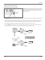
The battery compartment is located in the lower case on the backside of the trigger guard.
1. Position the unit face down.
2. Unscrew the two screws. Remove the battery door to expose the batteries.
3. Replace the old batteries with 4 AA alkaline batteries.
NNOTE: Battery polarity markings are inside battery compartment.
4. Dispose of used batteries properly, according to local regulations.
NNOTE: Changing the batteries does not affect any of the programmed values
or totals.
Programming the RF Meter
The units of measurement and scale factor can be changed. For instructions, see the RF Meter Installation and Operation
Manual.
July 2015
Page 31
Fluid Management System, LMS-RF Basic System
INSTALLING AND LAUNCHING THE LMS-RF SOFTWARE
The system configuration is done by using this LMS-RF Software. Only some special functions like the operation modes are set
at the Master Keypad.
The software provides the ability to set work orders, and assign a product and a quantity to it.
All dispense results will be collected and saved in a work order list (W.O. Report). Several filters are available to select the
desired information. The result can be exported to a semicolon separated value (CSV) file format.
System Requirements
•
•
•
P4 1.6 GHz or greater
1 GB RAM minimum
XP, Vista, or Windows® 7, Server 2003, Server 2008 Required (will not run on Windows 2000 or earlier) 64 and 32bit compatible
LMS-RF Software Description
Before beginning the installation, please be sure your Windows user profile has the appropriate rights to install the software
properly (particularly Windows XP).
Insert the setup CD ROM into your CD ROM drive.
If the Installer does not launch itself after a short period, open it manually by double clicking on your CD Drive in your My
Computer folder. Select the AutoMenu.exe file.
The installer menu will appear:
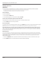
The installer menu provides several options:
• Server – installs the server and all server
components. This will be the location
where all the master keypad is plugged
in, data is stored and where the client
machine will go to access and update
work orders, tank levels, etc.
• Client – installs the client and all client
components. This will have to be
installed on every machine you would
like to run the software on
• Exit closes the installer
Page 32
July 2015
User Manual
Installing the LMS-RF Server
1. Select Install Server.
If the .NET 4.0 Framework or SQL Compact Edition is already installed, they will be skipped. If the .Net 4.0 Framework is not
installed, the installer will appear.
2. Click ACCEPT.
If the SQL Compact Edition is not installed, the installer will appear.
3. Click ACCEPT.
The Framework and/or SQL Compact Edition installation will take several minutes. The screens appear in the following order:
July 2015
Page 33
Fluid Management System, LMS-RF Basic System
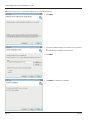
After the prerequisites are installed, the LMS-RF Server Setup Wizard appears:
1. Click NEXT.
1. Select the installation folder you want the Server installed
to.
The default folder is HIGHLY recommended.
2. Click NEXT.
3. Click NEXT to confirm the installation.
Page 34
July 2015
User Manual
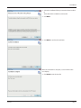
During the installation, a screen similar to this one displays,
showing the installation progress:
When the installation is complete, a screen similar to this
one displays.
4. Click CLOSE to exit the installer.
July 2015
Page 35
Fluid Management System, LMS-RF Basic System
Installing the LMS-RF Client
1. Select Install Client.
The .NET 4.0 Framework installer will appear here if the Client is being installed on a machine without it. The Client will also
install the SQL Compact Edition if it is not installed.
2. Click ACCEPT.
After the prerequisites are installed, the LMS-RF Client Setup Wizard screen appears:
1. Click NEXT.
Page 36
July 2015
User Manual
2. Select the installation folder you want the Client installed
to.
The default folder is HIGHLY recommended.
3. Click NEXT.
4. Click NEXT to confirm the installation.
When the installation is complete, a screen similar to this
one displays.
5. Click CLOSE to exit the installer.
July 2015
Page 37
Fluid Management System, LMS-RF Basic System
Launching the LMS-RF Software
To launch the software, click on the LMS-RF Client icon on your desktop
Before you can begin, you first need to tell the Client application the IP address where the server resides.
1. Enter the IP address of the LMS-RF server.
For the Client installed on the server, the IP address should be 127.0.0.1.
For the Client not installed on the server, enter the IP address assigned to the
server.
LMS-RF System Configuration
2. Enter the 4-digit system password and click the OK button.
The system admin password is initially set to 0000.
Page 38
July 2015
User Manual
USING THE LMS-RF SOFTWARE
Setting Up New Users
The default names and pins may be changed at any time by highlighting the text, deleting it, and entering the appropriate
text. To save changes made, click the SAVE button.
1. To add a new user, click the RESET button.
The information will clear from the text boxes.
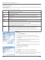
2. Enter a user name, new pin (cannot duplicate
any currently used pin number), and assign a
role.
If you wish to set up a user having multiple roles,
you will need to create a user and pin number for
each role.
New User Roles
The choices for role selection are System Admin, Supervisor, Parts Dept, and Dispense. These choices will allow the user to do
the following:
System Admin
Make changes to all levels of the software, from the PC only.
Supervisor
Make changes at the keypad only.
Parts Dept
Enter work orders at the PC.
Dispense
Enter a work order id at dispense keypad to complete dispense..
Active or Inactive Users
Only users who have an Active status will be allowed to access their respective duties.
To make a user active or inactive:
1. Select the user's name.
2. Check the Active box.
3. Click SAVE.
Users with multiple roles will require a unique password for each role.
Deleting a User
To delete a user:
1. Select the user's name.
2. Click the DELETE USER button in the top left-hand corner.
3. Confirm your request to delete the user.
July 2015
Page 39
Fluid Management System, LMS-RF Basic System
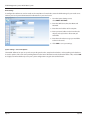
Setting Up Tanks and Fluids
Using the software, you can track and monitor tank levels based off work orders. To track this, you first need to add a tank and
its corresponding fluid.
These are the fields of information required to add a tank:
Tank ID
The Tank ID field automatically displays the next available sequential ID number. You can also select
available tank IDs from the drop-down menu.
Units
The Units field specifies the units of measurement that you use to track the tank level. The choices are
Gallons, Liters, Pints and Quarts.
Fluid
The Fluid field specifies the type of fluid in the tank. You can also select existing fluids from the
drop-down menu.
Capacity
The Capacity field specifies the total amount of fluid that may be stored in that tank. Enter a numeric
value that corresponds to the capacity of the tank (the value will be in the units you previously
identified).
Level
The Level field specifies the current level of fluid in the tank.
Warning Level
The Warning Level field specifies the fluid level at which you would like a warning message emailed to a
particular person. A warning message will appear on any running client screen when a completed work
order brings the tank level down to, or below, the warning level setpoint.
To use this feature, click the check box and enter either a nominal value or percentage (the other value
with self-propagate after you enter the first value).
Auto Email
Check the Auto Email checkbox to bring up a screen to specify email settings for the warning message.
When the tank reaches the specified Warning Level, this email will be sent to the email recipient.
Multiple recipients can be defined. Enter a semicolon ( ; ) between each e-mail address.
NNOTE: This is not a required field. This option will not run if email settings are not activated. See “Email
Settings” on page 46.
To set up a tank:
1. Click on the ADD TANK button.
2. In the Units field, select a unit of measure from the drop-down menu.
3. In the Fluid field, enter a fluid name in the text box or select a fluid from the
drop-down menu.
4. In the Capacity field, enter the total number of units (gallons, liters, pints or
quarts) of fluid that may be stored in the tank.
5. In the Warning Level field, enter the fluid level at which to trigger a warning
message.
6. To specify the email setting for the warning message, check the box next to
Auto Email, then select Email Options.
7. Enter the email address of the recipient.
8. Type a message.
9. Click SAVE to close this screen and return to the Add Tank screen.
10.Click SAVE again to save your changes and exit the Add Tank screen.
NNOTE: If the fluid you entered was not in the drop-down list, you will be asked if
you want to create a new fluid when you exit this screen.
Page 40
July 2015
User Manual
Creating a New Fluid
11.If the fluid you entered during the Add Tank procedure was not in the dropdown list, click YES if you want to create a new fluid.
The new fluid will now appear in the Fluid Type drop-down list.
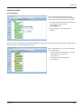
After you set up a tank and fluid(s), the software
displays graphical representation of the tank
level, including:
• the percentage of fluid remaining in the tank.
• the tank information that was entered in the
previous step.
To change the information, click on EDIT.
To add a new tank, click on ADD TANK and
repeat the process explained in “Setting Up Tanks
and Fluids” on page 40.
To track when fluid is added to the tank, click on
FLUID DELIVERY.
You can edit the amount of fluid added and the units in which it was added
(gallons, liters, pints, and quarts).
After entering the information, click SAVE to save your changes.
You will be asked to verify your changes.
When the verification screen appears, click OK.
July 2015
Page 41
Fluid Management System, LMS-RF Basic System
Setting Up Keypads and Hoses
Adding keypads and hoses allows you to build out your entire system and send work orders to the appropriate stations.
Global Keypad Settings
Before starting, make sure your Global Keypad Settings are configured correctly.
1. Click the SETTINGS button.
2. Change any settings according to the
“Dispense Keypad Settings” and “Master Keypad
Settings” tables below.
3. Click SAVE to save your changes or CANCEL
to discard the changes and return to the Main
screen.
Dispense Keypad Settings
Distance Units
Specifies the units (miles or kilometers) of odometer readings for each WO.
Odometer
To request that mileage be tracked, check the Odometer checkbox.
Registration
To request that the car registration number be tracked, check the Registration checkbox. This
allows the system users to enter the car registration number in the Pending WO and save it to the
Completed WO.
Display Timeout
Sets how long (in minutes) a PIN will be able to sit idle before timing out and forcing the user to log
back in.
Top off Timer
Sets the time that the user is allowed to keep the meter open after the allotted amount of fluid has
been dispensed (timer is in seconds).
Barcode Timeout
The amount of time in increments of 10 ms to display the entered parameter on the screen after
the barcode scanner input is entered. A value of 100 will equal 1000 ms or 1s of display time. This
timeout is only used when the barcode scanner feature is selected on the keypad.
Int. Printer
If you have an optional internal printer connected to the keypad, select the checkbox next to the Int.
Printer field.
Buzzer
To activate the key click buzzer, check the box next to the Buzzer field.
Keypad RF Timeout
Sets how long (in minutes) a PIN will be able to sit idle before timing out and forcing the user to log
back in.
Miscellaneous WO
A configurable numeric input that allows the user to define what number a miscellaneous work
order gets. This would be used in the event any fluid needs to be dispensed independent of a system
work order. The miscellaneous work order number along with the user ID number will be in the work
order report. To change, simply highlight the number, delete, and enter a new number.
Auto Override
Activates System Auto Override feature in all keypads so users can dispense WOs when the Master
Keypad is not operational. No supervisor intervention is required. Available with v3.X firmware only.
Page 42
July 2015
User Manual
Master Keypad Settings
COM Port
Select the COM port on the PC for the serial connection to the Master Keypad. To change, simply
click on the drop down and select the appropriate COM port.
Buzzer
To activate the key click buzzer, check the box next to the Buzzer field.
Adding a Dispense Keypad
1. From the Keypad and Hoses screen, click ADD KEYPAD.
2. Enter the Dispense Keypad address found on the back of the keypad. Use only
the last 8 characters as shown here:
Keypad address
3. The ID field automatically displays the next available sequential number.
4. Click SAVE.
Adding Hoses
Once you have added a keypad, you can begin adding hoses associated with it. You can also enter hoses not associated with
any keypad. You can drag and drop hoses to a keypad or between keypads.
To add hoses, fill in the information at the bottom right-hand corner of the Keypad
and Hoses screen:
1. Enter the hose ID found on a tag on the meter.
2. Enter the hose Address.
3. Enter the Tank the fluid will be dispensed from.
4. Enter the dispenser Units of measure of the meter.
5. Click SAVE.
After the hose is added, it will appear under the Unused Hoses section or under the selected keypad.
Associating an Unused Hose with a Keypad
To associate an unused hose with a keypad:
1. Drag and drop the hose from the Unused Hoses section to the keypad section.
OR
2. Move it manually by selecting the hose(s) from the list on the right and
assigning them to keypads using the drop-down next to the Move Hoses to:
field.
To delete a hose, select it on the left and click the DELETE HOSE button.
July 2015
Page 43
Fluid Management System, LMS-RF Basic System
System Settings
To change system settings, select the System Settings tab on the left-hand side. A screen similar to the one below appears:
1. Change any settings according to the tables
below.
2. Click SAVE to save your changes or CANCEL
to discard the changes and return to the Main
screen.
System Settings Fields
Location
Location is set as a factory default and cannot be changed by the user.
Skip Failed DK in Init
The system can be configured to skip a keypad that it cannot communicate with and
continue with the initialization process. To activate this, check the box next to Skip Failed DK
in Init.
Decimal Point
Select a period or comma as the decimal point.
Firmware Version
Select the firmware version your master and Dispense Keypad is using. Version 1x can
support 99 meters, version 2x and version 3x for 2.4 GHz radios can support up to 250
meters.
Auto Log Off
If you would like the software to automatically log off the PC user after a specified period of
time, check the box next to Auto Log Off and chose the time (in minutes) you would like the
PC user to remain idle before being logged off.
Email Completed WO
Work Orders may be emailed or printed upon completion. To set this up, check the box next
to the corresponding text. There are two buttons in the Functions section.
Print Completed WO
Use the Printer Settings button to select a printer that is available on your network. Use the
Page Setup to set up paper formatting information. Enter text that you want to appear on
the printout in the work order message box. Make the appropriate changes, then click SAVE
to save your changes and exit the printer settings. The CLEAR button will reset all of the
information on the form.
Allow Users to Delete WOs
To allow dispense users to delete work orders, check the box next to the
Allow Users to Delete WOs field.
Allow Users Fluid Delivery
To allow dispense users to enter a fluid delivery, check the box next to the
Allow Users Fluid Delivery field.
* Auto Override
Enables the Dispense Keypad to automatically enter System Override mode when
communication is lost to the Master Keypad.
* Available for v3.x firmware only.
Page 44
July 2015
User Manual
System Settings – Functions Options
Log Viewer
Use the Log Viewer to display system activity logs based on the parameters you choose.
1. From the System Settings screen,
select LOG VIEWER.
2. Check the boxes next to the options you want
to display. The options are:
•
•
•
•
•
•
Server
Client
Details
INIT
Error
Date Range
3. Click Submit.
4. At this point, you can click the EXPORT button
to save the file.
Printer Settings
1. From the System Settings screen, select PRINTER SETTINGS.
2. Click SELECT PRINTER and chose a printer.
3. Click PAGE SETUP to set up paper formatting information.
4. Enter text that you want to appear on the printout into the Work Order Message
box.
5. Click SAVE to save your changes and exit the printer settings. .
July 2015
Page 45
Fluid Management System, LMS-RF Basic System
Email Settings
To configure the software to send an email on the completion of a work order, enter the SMTP settings for your email server.
Contact your local system administrator for information on your email server.
1. From the System Settings screen,
select EMAIL SETTINGS.
2. Enter the SMTP Server, Port, User Name and
Password.
3. Enter the email address of the recipient.
4. Enter your email address in the From line, the
subject, and any header or footer text you
would like.
5. Enter the work order message you would like
to have in the email.
6. Click SAVE to save your settings.
System Settings – Save to File Options
The LMS-RF Software lets you set up and save pending work orders, completed work orders, and everything in the database.
To use this option, click on the corresponding buttons under Save to File. Browse to the destination folder or file, and click OK.
It is highly recommended that you save your system configuration using the Save to File function.
Page 46
July 2015
User Manual
INITIALIZE SYSTEM
Test Comm Option
The Test Comm option checks that the serial
cable is connected to the Master Keypad and the
correct communication port has been selected.
1. To test the serial communication between the
Master Keypad and PC, click the
TEST COMM button.
2. Upon completion, a Test Passed screen
displays.
After the system is configured you will need to initialize the system before using. The first time you select the Initialize System
option, you will see a screen similar to the one this:
All items highlighted are color-coded to indicate
their initiation status:
• Orange indicates an initialization is required.
• Green indicates the items have
been initiated.
• Red indicates that the initialization
process failed.
July 2015
Page 47
Fluid Management System, LMS-RF Basic System
Initialize All Option
The Initialize All option initializes all parts of the system. This is the option to use for the first initialization.
Initialize Changes Option
The Initialize Changes option initializes only the changes made since the last initialization.
After clicking the appropriate button, you will be reminded that everything currently on the keypads will be erased. Click YES
to continue or NO to go back. The initialization process may take several minutes. Upon completion, a Request Completed
screen displays.
After the system is initialized, if changes are made to the system configuration it will be necessary to initialize those changes
before the system can be used. You will not be allowed to make changes to the system if there are pending work orders.
To initialize only the changes, click the INITIALIZE
CHANGES button. Any items that are highlighted
in red did not initialize properly and it will be
necessary to determine what is wrong. All custom
settings initiated by the supervisor user will
be erased.
On the right-hand side is the log of all Master
Keypad communications during an initialization
or communications test. To clear this log, click the
CLEAR LOG button.
Page 48
July 2015
User Manual
PARTS DEPARTMENT USER MENU
The parts department user can enter work
orders, view work order reports, and enter a fluid
delivery, if enabled.
Upon login, the screen to the left displays:
Creating a New Work Order
To enter a new work order:
1. Click on the WORK ORDER option.
2. Enter a work order number in the Work Order
ID field.
3. Enter a Quantity and type of Fluid to be
dispensed in the respective fields.
4. Click SAVE.
Optionally, a zero quantity can be entered in the
quantity and the dispense user can select the
quantity at the keypad. Work Orders are stored on
the PC until requested by a dispense user. Work
orders can be deleted by selecting them and
clicking the DELETE key.
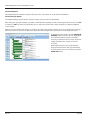
Work Order Reports
To see if a work order has been completed by
other personnel, click on the W.O. REPORTS
option. If no work orders have been completed,
the screen to the left displays:
July 2015
Page 49
Fluid Management System, LMS-RF Basic System
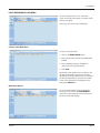
The default view shows all work orders that
have been completed on that day. If you have a
work order completed you will see it listed in the
screen to the left:
The columns across the top show:
• the work order ID number assigned,
• date and time the fluid was dispensed,
• the quantity of fluid actually dispensed,
• the quantity that was preset on the work order,
• the user who dispensed the fluid,
• the type of fluid dispensed,
• the hose the fluid was dispensed from,
• the status of the work order, and
• whether the work order has been reviewed.
Reviewing a Work Order
To mark a work order as reviewed, check the box below Reviewed and press ENTER.
Locating a Work Order
To locate a work order, you may search by user, work order ID, hose ID, fluid type, or date range.
To search, enter your criteria in the appropriate text boxes and click NEW SEARCH. To clear the search criteria, click RESET.
Changing the Unit of Measure
At the bottom of the screen, there are total fluid numbers and records counts. This will sum the total amount of fluid that has
been dispensed for the records currently appearing on the search. You may change the unit that the fluid is summed in by
selecting the drop-down menu next to Unit and choosing from Liters, Gallons, Pints, and Quarts.
Page 50
July 2015
User Manual
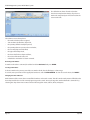
Deleting Old Work Orders
To delete old work orders:
1. Click the DELETE button.
2. On the pop-up screen, select either the date
you would like to keep work order from
(everything on and after July 6th, 2010) or the
number of days (everything from 3 days ago
and after) and click OK.
3. When asked to confirm the deletion, click YES.
A Request Completed screen displays.
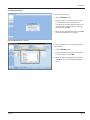
Exporting Work Orders to a CSV File
To export work orders to a semicolon-separated
value (CSV) file:
1. Click the EXPORT button.
2. Select the folder/location that you would like
to save the file to and click OK.
3. When the Request Completed screen displays,
click OK to return to the Work Order Reports
screen.
July 2015
Page 51
Fluid Management System, LMS-RF Basic System
Tanks and Fluids
Viewing Tank Status
To view the status of tanks in your system:
1. Click the TANKS & FLUIDS button.
2. View the current status and information.
To add fluid:
The information displayed includes:
• The tank ID
• Type of fluid in that tank
• Current level of the tank
• Total capacity of the tank
Adding Fluid to a Tank
If this feature is enabled, you can add fluid upon delivery.
To add fluid to a tank:
1. Double-click on the tank or select the tank
and click on FLUID DELIVERY.
2. Select the unit of measure the fluid will be
delivered in (gallons, quarts, liters, or pints).
3. Enter the amount (in the selected units) of
fluid that is being delivered.
4. Click SAVE to save your changes or click
CANCEL to discard your changes.
5. Click OK on the verification screen to proceed,
or click CANCEL to edit.
If you enter an amount that brings the tank over
the capacity amount, the tank will appear in a red
“Warning” state until the proper amount of fluid is
removed via work order or the administrator goes
into the software and manually adjusts the level
of the tank.
Only the system administrator can correct a
tank level.
To exit the software, click the EXIT button.
When tank level warnings are enabled and a
fluid dispense causes the tank level to hit the
warning level, a message will appear on all part
department users screen. Click OK to clear the
message.
To exit the software, click the EXIT button.
Page 52
July 2015
User Manual
TROUBLESHOOTING
Dispense Keypad Error Messages
These error messages can be displayed by the Dispense Keypad. The associated action to reset the system is listed behind.
Message
Messages at the Dispense Keypad
Hose active hit hose reset
The selected meter currently has a dispense order in waiting to be processed, complete
the active order. Press RESET.
WO refused
The entered work order number is not valid and has been refused by host or LMS-RF
software.
Master is down
The master does not respond to a request from the Dispense Keypad
PC is down
The LMS-RF software (KPS) is not responding to the Master Keypad. Only if WO validation
PC is activated.
HOST is down
The HOST (DMS) is not responding to the Master Keypad. Only if “WO Validation HOST” is
activated. Press RESET.
Host or PC is occupied
Master keypad is occupied by another job. Press RESET.
Wrong hose for fluid
↑↓
The meter selected is not a valid meter for the fluid assigned for this WO.
RF communication is in progress, please wait (10 sec).
Meter Error Codes
The meter has several Error Codes that may display. These provide indication, at the meter, that there is an error in
communication between the meter and keypad.
Message
Messages at the Meter
F01
The meter radio is not working.
F02
The meter is not configured to a keypad.
To clear the error, press the RESET button on the meter.
To clear the error code, press the RESET button on the meter.
Verify that the meter radio address is configured properly.
F03
System busy.
To clear the error, press the RESET button on the meter.
F08
Meter lost connection to network.
Out of range—network connection lost.
Keypad not powered.
Meter moved out of range of keypad.
F09
Meter not connected to a network.
First time being powered up.
Network selected is not available.
SF0
(Scale Factor 0)
The Scale Factor setting for the meter is set to 0.000.
All other
Error Codes
Are for factory purposes only.
To input a valid Scale Factor for the meter follow the instructions in the Change Factory Settings section
of this manual.
To clear the meter, press RESET.
Press RESET once more at the meter.
July 2015
Page 53
Fluid Management System, LMS-RF Basic System
WORKSHEETS
Tank ID
Units
Fluid
Capacity
Level
1
2
3
4
5
6
7
8
9
10
11
12
13
14
15
16
Maximum: 16 Tanks
Tank volume format: 00000.000
Keypad ID
Address xx . xx . xx . xx
1
2
3
4
5
6
7
8
9
10
11
12
Maximum: 36 Dispense Keypads
RF-Keypad address is an 8-digit number.
Page 54
July 2015
User Manual
Meter ID
Address x . xxx . xxx . xxx
Tank
Unit
Keypad
1
2
3
4
5
6
7
8
9
10
11
12
13
14
15
16
17
18
19
20
21
22
23
24
Maximum: 250 Meters/Hose
Meter/ Hose address is a 10-digit number.
July 2015
Page 55
Fluid Management System, LMS-RF Basic System
User ID
Name User
PIN ID
Role
1
2
3
4
5
6
7
8
9
10
11
12
13
14
15
16
17
18
19
20
21
22
23
24
25
26
27
28
29
30
31
32
33
34
35
36
37
38
39
40
41
42
43
44
45
The user field is alphanumeric with a maximum of 16 characters.
The user PIN ID is a 4-digit number.
Number of Users Allowed:
• Supervisor – 1
• Dispense Users – 249
• Parts Department – 250
• Admin – 100
Page 56
July 2015
User Manual
INTENTIONAL BLANK PAGE
July 2015
Page 57
Fluid Managment System, LMS -RF Basic System
INTENTIONAL BLANK PAGE
Page 58
July 2015
User Manual
INTENTIONAL BLANK PAGE
July 2015
Page 59
Hotline
Tel.+49-7025-9208-0
Fax+49-7025-9208-15
E-mail: [email protected] or
[email protected]
Badger Meter Europa GmbH
Subsidiary of Badger Meter, Inc.
Nürtinger Strasse 76
72639 Neuffen (Germany)
E-mail: [email protected]
www.badgermeter.de