1
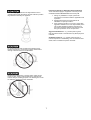
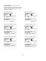
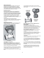
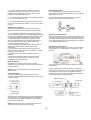
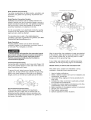
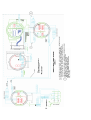
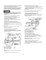
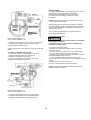
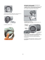
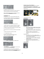
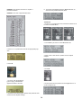
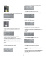
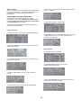
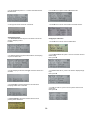
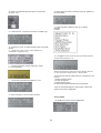
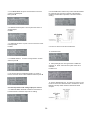
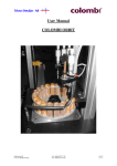
IMPORTANT !!!! Read this manual before attempting any handling
or installation of the meter.
BME-M3000-09-07
Disclaimer
The user/purchaser is expected to read and understand the information provided in this manual, follow any listed Safety
Precautions and Instructions and keep this manual with the equipment for future reference.
The information in this manual has been carefully checked and is believed to be entirely reliable and consistent with the product
described. However, no responsibility is assumed for inaccuracies, nor does Badger Meter Europe assume any liability arising out
of the application and use of the equipment described.
Should the equipment be used in a manner not specified by Badger Meter Europe, the protection provided by the equipment may
be impaired.
Questions or Service Assistance
If you have questions regarding the product or this document contact:
Badger Meter Europa GmbH
Nürtinger Str. 76
72639 Neuffen (Germany)
Telephone: +49-7025-9208-0
Fax: +49-7025-9208-15
On the Web: www.badgermeter.de
or call your local Badger Meter representative.
Product Identification Information
Record the product identification numbers from the
nameplate.
Modular Mag Meter
Model Number _M3000______
Serial Number _____________
Tag Number _______________(if applicable)
2
Basic safety advices
The electromagnetic flow meter is only suitable for the measurement of conductive fluids. The manufacturer is not liable for
damages that result from improper or nor not in accordance with the requirements use.
The meters are constructed according to state-of-the-art technology and tested operationally reliable. They have left the factory in a
faultless condition concerning safety regulations.
The mounting, electric installation, taking into operation and maintenance of the meter may only be carried out by suitable
technicians. Furthermore the operating personnel has to be trained by the operating authority and the instructions of this manual
have to be followed.
Principally the regulations for the opening and repairing of electrical equipment in your country have to be payed attention.
Repairs
Should you send back a flow meter in operation, please take notice of the following points:
- Please enclose a description of the fault as well as a precise statement of the measured medium (if necessary a safety
specification sheet).
- The meter has to be in a cleaned condition (outside and inside). Especially with harmful measuring mediums you have to pay
attention that there are no impurities in the pipe or at the connections.
- If it is not possible to clean the meter completely, particularly with harmful materials, do not send back the meter.
We reserve the right to repair only cleaned meters. Costs, which result from insufficient cleaning, will be charged to you.
CE mark
The electromagnetic flow meter complies with the European regulation ATEX 94/9/EC,
EMC regulation 2004/108/EC and PED regulation 97/23/EC.
The device is so designed and manufactured that it cause no danger by direct or indirect contact.
Badger Meter Europe confirm the conformity with the European regulations by printing the CE sign on the meter.
3
TABLE OF CONTENTS
Disclaimer
Questions or Service Assistance
Product Identification Information
Basic saftey and repair advise
CE mark
2
2
2
3
3
SAFETY PRECAUTIONS and INSTRUCTIONS
Equipment Unpacking, Inspection, Moving and Return Policies
Rigging, Lifting, Moving Large Units
Instructions Specific to Hazardous Area Installations
6
6
7
METER DESCRIPTION
Empty Pipe Detection
Amplifier Mounting Options
Meter Mount
Remote Mount
9
9
9
9
9
METER/AMPLIFIER LOCATION, ORIENTATION and APPLICATIONS
Remote Amplifier Outdoor Location
Temperature
Pipelines and Fluid Flow
Meter Orientation
Vertical Placement .
Horizontal Placement
Straight Pipe Requirements ..
Pipe Reducer Requirements .
Chemical Injection Applications
Partially Filled Pipe Situations .
Meter Gaskets and Grounding
9
9
9
10
10
10
10
10
10
11
11
12
METER INSTALLATION
Remote Mount Amplifier
Remote Mount Amplifer/Detector Wiring
Detector Junction Box
Remote Mount Wiring Diagram
Electrode and Coil Wiring from Detector Junction Box to Remote Mount Amplifier Junction Box
Electrode Wiring
Coil Wiring
Output Wiring
External Disconnect
AC Power Wiring
Adjustable Display/Control Card .
12
13
13
13
14
15
15
15
17
18
18
19
AMPLIFIER CONTROLS, CONTROL METHODS AND DATA DISPLAY PROGRAMMING
Card Display and Controls
Two Programming Methods
Main Screen(s)
Password
Amplifier Access Switches/Buttons
How to Program
What to Program
20
20
20
20
21
22
22
26
PROGRAMMING REQUIRED PARAMETERS
Input a Password
Set Flow Units
Set Full Scale Flow
Set Flow Direction
Set Damping Factor
Empty Pipe Calibration .
Pulse Output
Analog Output
26
26
27
27
28
28
28
29
31
4
ADDENDUM A
Detector Specifications
Amplifier Specifications
34
34
35
ADDENDUM B
Maintenance
Flow Tube and Electrode Cleaning
Fuse Replacement
Amplifier PCB Stack Replacement
36
36
36
36
37
ADDENDUM C
Menu Structure Flow Chart
40
ADDENDUM D
ATEX Certificate
42
42
5
SAFETY PRECAUTIONS and
INSTRUCTIONS
NOTE: Do not remove the liner protector until installation.
Safety considerations are emphasized by the placement of
safety symbol icons on the product or next to important text,
pictures or drawings throughout this manual. The symbols
are:
8. Storage: If the meter is to be stored, place it in its original
container in a dry, sheltered location. Storage
temperature ranges are: -4°F to 158°F (-20°C to 70°C).
Rigging, Lifting, Moving Large Units
When and where this symbol is attached to the product
it indicates a potential hazard. It means that
documentation must be consulted to determine the
nature of the potential hazard and any actions that need to
be taken.
DO NOT lift or move a meter via its amplifier, junction box
or cables.
Lift and move meters with flow tubes between 2" and 8" (50
and 200mm) with a crane rigged with soft straps. Place a
strap around the detector body, between the flanges, on
each side of the detector.
Warning indicates an action or procedure, which, if not
performed correctly, can result in sever personal injury,
death, or substantial property damage. Comply with the
instruction and proceed with care.
Caution indicates an action or procedure, which if not
performed correctly, will or can cause minor personal
injury or property damage. Comply with the instruction
and proceed with care.
Equipment Unpacking, Inspection, Moving and
Return Policies
1. If shipping container damage is evident at delivery, have
a responsible person present when the meter is unpacked.
2. Inspect the shipping container for unpacking, lifting or
moving instructions.
3. As the unit is opened and unpacked, verify the shipment
packing list and your order form match the items in the
shipment.
4. Open the container and remove all cushioning materials.
Keep the shipping container and packing materials should
the meter need to be returned or put in storage.
5. Remove the meter from the container. For meter flow
tube diameters between 2” and 8” (50 and 200mm) use a
crane or lifting device with soft straps placed around the
detector body, at the flanges. For meter flow tube diameter
sizes 10” (250mm) and larger, lift the unit via the lifting lugs
with a crane, cables and hooks.
6. Inspect the meter for signs of shipping damage;
scratches, loose or broken parts.
Lift meter flow tube diameter sizes 10" (250mm) and larger
via its lifting lugs. Use the proper size crane, cables and
hooks. DO NOT lift the meter by the amplifier or, on remote
style meter, by the junction box.
NOTE: If damage is found, a formal claim for damage in
transit is the responsibility of the customer. Within 48 hours
of delivery request an inspection report from the carrier. File
a claim with the carrier. Contact the Badger Meter factory to
facilitate repair or replacement, +49 7025 92080.
7. All detectors with PTFE liners are shipped with a liner
protector to maintain proper form of the PTFE material
during shipping and storage.
6
Instructions Specific to Hazardous Area Installations
These instructions apply to equipment covered by ATEX
Certificate Number FM08ATEX0051X issued by FM.
Use the sling-rigged method to lift large detectors into a
vertical position while still crated. Use this method to position
large detectors vertically into pipelines.
1. During any installation or repair, perform all
procedures in accordance with the applicable code
of practice.
2. Suitably trained personnel shall perform all
installation or repair procedures.
3. If the equipment is likely to come into contact with
aggressive substances, it is the responsibility of the
user to take suitable precautions that prevent it
from being adversely affected, thus ensuring that
the type of protection is not compromised.
Aggressive Substances – e.g. acidic liquids or gases
that may attack metals or solvents that may affect polymeric
materials.
Suitable Precautions – e.g. regular checks as part of
routine inspections or establishing, from the material’s data
sheet, that it is resistant to specific chemicals.
Do not lift a detector with a forklift via the detector body
between the flanges. The housing could be dented and/or
damage caused to internal coil assemblies.
NEVER place forklift forks or rigging chains, straps, slings,
hooks or other objects inside or through the detector flow
tube for lifting or handling purposes. The isolating liner could
be damaged, rendering the unit inoperable.
7
Additional Information
Certification markings are noted on the product label.
For additional information regarding importation, equipment
installation, equipment repair, equipment return or renewal
parts, please contact Badger Meter Europe or your local
Badger Meter representative.
Meter mounted 85-240 VAC
Meter mounted 24 VDC
Remote mounted 85-240 VAC - Amplifier
Remote mounted 24 VDC - Amplifier
Remote mounted 85-240 VAC - Detector
Remote mounted 24 VDC - Detector
8
METER DESCRIPTION
Badger Model M3000 electromagnetic meters are ATEX
approved for Zone 2 hazardous locations. To achieve
hazardous location ratings electrodes in the flow tube are
Intrinsically Safe, designed according to ATEX standards.
Those standards limit the amount of energy that can be sent
to electrodes to prevent a spark from occurring.
This configuration can also provide a more convenient
amplifier programming and display placement for monitoring
meter readings.
Empty Pipe Detection
Badger Magnetoflow Mag meters are equipped with an
Empty Pipe Detection feature. Empty Pipe Detection is
accomplished by positioning a third electrode between 12
o’clock and 1 o’clock. Any time this electrode is not covered
by fluid, for a minimum of five seconds, the meter displays
an Empty Pipe Detection condition, sends out an error
message if desired, and stops measuring to maintain
accuracy. When the electrode is again covered with fluid, the
error message disappears and the meter continues
measuring.
Amplifier Mounting Configuration Options
Two amplifier-mounting configuration options are available to
meet a variety of meter placement and environmental
conditions.
Meter Mount Configuration
The Meter Mount configuration has the amplifier mounted
directly on the detector. This compact, self-contained
configuration minimizes installation wiring.
METER/AMPLIFIER LOCATION, ORIENTATION and
APPLICATIONS
Remote Amplifier Outdoor Location
The amplifier can be installed and operated outdoors.
However, protection from the elements must be considered:
1. Be aware of the ambient environment and temperature
ratings for the unit -4°F to 122°F (-20°C to 50°C).
2. If an indoor location is within 100 feet (30m) of the
detector installation, consider increasing the cable length
and mounting the amplifier indoors.
3. Consider mounting the amplifier in a IP 67 outdoor
enclosure.
4. At a minimum, fabricate a roof or shield over and/or
around the amplifier to protect the LCD display screen from
sunlight and to keep the possibility of rain or moisture
problems to a minimum.
Temperature
To prevent meter damage in any environment, minimum and
maximum temperature ranges must be observed.
1. For remote amplifier applications, the fluid temperature
range is -4°F to 221°F (-20°C to 105°C) at a maximum
ambient temperature of 122°F (50°C) for the following liner
materials: PTFE.
Meter Mount
2. For remote amplifier applications, the fluid temperature
range is 32°F to 178°F (0°C to 80°C) at a maximum ambient
temperature of 122°F (50°C) for the following liner materials:
Hard rubber.
Remote Mount Configuration
Remote Mount configuration places the amplifier and its
functions at a location separate from the fluid flow and
detector. This configuration is necessary in situations where
process fluid temperature or environment exceeds amplifier
ratings. A remote mounting bracket is supplied.
3. For meter mounted amplifier applications, the fluid
temperature range is -4°F to 212° (-20°C to 100°C) at a
maximum ambient temperature of 122°F (50°C) for the
following liner materials: PTFE.
Detector and amplifier are connected by wires, run through
conduit, between junction boxes on the detector and remote
mounted amplifier. The distance between the detector
junction box and amplifier junction box can be up to 100 feet
(30m).
9
4. For meter mounted amplifier applications, the fluid
temperature range is 32°F to 178°F (0°C to 80°C) at a
maximum ambient temperature of 122°F (50°C) for the
following liner materials: Hard rubber.
Horizontal Placement
In a horizontal piping orientation, mount the detector to
piping with the flow measuring electrode axis in a horizontal
plane (3 and 9 o’clock).
5. The ambient temperature range surrounding the amplifier
is -4°F to 122°F (-20°C to 50°C.)
This arrangement prevents solids build-up or sediment
deposit or accumulation on the electrodes.
6. The ambient temperature range surrounding a remote
junction box mounted to the detector is -4°F to 122°F (-20°C
to 50°C.)
Pipelines and Fluid Flow
Although the Model M3000 is rugged, there are some
pipeline and fluid flow conditions that should be avoided:
1. Do not install the meter where extreme pipe vibrations
exist. If vibrations are present, secure piping before and after
the meter with appropriate pipe supports. If vibrations can’t
be restrained, consider mounting the amplifier remotely.
2. Avoid installing the detector close to pipeline valves,
fittings or impediments that can cause flow disturbances.
3. For detectors with PTFE liners, avoid installing the
detector on suction sides of pumps.
4. Avoid installing the detector on outlet sides of piston or
diaphragm pumps. Pulsating flow can affect meter
performance.
5. Avoid locations near equipment producing electrical
interference such as electric motors, transformers, variable
frequency, power cables, etc.
6. Verify both ends of the signal cables are securely
fastened.
7. Place power and signal cables in separate conduit.
8. Place the meter where there is enough access for
installation/maintenance purposes.
Straight Pipe Requirements
Sufficient straight pipe runs are required at the detector inlet
and outlet for optimum meter accuracy and performance. An
equivalent of three (3) diameters of straight pipe is required
on the inlet (upstream) side. Two (2) diameters are required
on the outlet (downstream) side.
Pipe Reducer Requirements
With pipe reducers a smaller size meter can be mounted in
larger pipelines. This arrangement may increase low flow
accuracy.
Meter Orientation
Mag Meters can operate accurately in any pipeline
orientation and can measure volumetric flow in forward and
reverse directions.
There are no special requirements for standard, concentric,
pipe reducers.
Custom fabricated pipe reducers must have a minimum
slope angle of 15 degrees to minimize flow disturbances and
excessive loss of head. If this is not possible, install the
custom pipe reducers as if they were fittings and install the
amount of straight pipe stated previously.
NOTE: A Forward Flow direction arrow is printed on the
detector label.
Vertical Placement
Mag meters attain optimal performance when placed
vertically, with liquid flowing upward and meter electrodes in
a closed, full pipe.
Vertical placement allows the pipe to remain completely full,
even in low flow, low pressure applications and it prevents
any solids build-up or sediment deposit or accumulation on
the liner and/or electrodes.
NOTE: Carefully observe the “Forward Flow” label on the
meter body and install the meter accordingly.
10
Chemical Injection Applications
For water line applications with a chemical injection point,
install the meter upstream of the injection point. This
eliminates any meter performance issues.
If a meter must be installed downstream of a chemical
injection connection, the distance between the meter and
the injection point must be significant; 50 to 100 feet (15 to
30 meters). When the water/chemical solution reaches the
meter it must be a complete, homogeneous mixture. If the
.
injection point is too close, the meter senses two (2) different
liquids (conductivity is different for each) and correct data
output cannot be assured. The injection method: spaced
bursts, continuous stream of drips, a liquid or gas can also
affect downstream readings by the meter.
Do not install the meter in a vertical,
downward flow section of pipe
Sometimes it’s difficult to specify the exact downstream
placement distances because of the number of variables.
Contact Badger Meter Technical Support, +49 7025 92080,
to review your application if necessary.
Partially Filled Pipe Situations
It is possible to encounter situations where the process pipe
is momentarily only partially filled. Examples include; lack of
backpressure, insufficient line pressure, gravity flow
applications, etc.
ALWAYS locate ON/OFF valves on the
downstream side of the meter
To eliminate these situations:
Do not install the meter in
the highest point of the pipeline
To minimize the possibility of partially full pipe flows in
horizontal, gravity or low pressure applications, create a pipe
arrangement that insures the detector remains full of liquid at
all times.
11
12
For Remote Mount Units consider:
1. Amplifier location.
2. Remote amplifier mounting bracket.
3. Proper conduit and conduit fittings.
4. Wiring and conduit locations.
REMOTE MOUNT AMPLIFIER
NOTE: Screws are supplied to attach bracket to amplifier.
Screws are not supplied to attach bracket at mounting
location.
NOTE: Not relevant to meter mount units.
Remote Mount Amplifier Location Requirements:
1. A sturdy and safe mounting surface capable of holding the
amplifier weight (20 pounds, 9 Kg).
2. Within the allowable temperature range: -4°F to 122°F,
(-20°C to 50°C).
3. Access to amplifier covers, ports, terminals, screen and
adjustments.
4. As close to the detector as possible.
5. Determine length and route of cable/conduit runs.
(Refer to the Remote Mount Wiring Diagram on page 15.)
Detector Junction Box
The Detector Junction Box has one chamber and two wire
ports. The Junction Box, Chamber and wiring ports provide
openings for wire, conduit, tool and hands access to terminal
blocks. Detector to remote mount amplifier electrode and coil
wires connect to the detector through the chamber wire
ports.
Use the supplied remote mount amplifier bracket to secure
the remote mount amplifier at a desired location. An amplifier
unit weighs approximately 20 pounds (9 Kg).
Mount Bracket to Amplifier
1. Align bracket-mounting holes with amplifier mounting
holes.
2. Attach bracket to amplifier with supplied screws. Torque
screws to 80 in. lb.
Mount Bracket/Amplifier to Location
1. Position the bracket/amplifier in the desired orientation.
2. Secure bracket/amplifier to location.
· Suitably trained personnel shall perform all installation
or repair procedures.
· Disconnect power to the unit before attempting any
installation or maintenance.
· Do not bundle or route signal wires with power wires.
· Use proper conduit, connections and supplied cables
in all wiring procedures.
· Observe all local applicable electrical codes when
wiring any equipment.
REMOTE MOUNT AMPLIFIER/DETECTOR WIRING
Remote Mount Amplifier
The remote mount amplifier has three chambers and five
wire ports. The Junction Box and Connections Chambers
and wiring ports provide amplifier openings for wire, conduit,
tool and hands access to amplifier terminal blocks. Detector
to amplifier wires connect in the Junction Box Chamber.
The Display/Programming Chamber provides access to
fuses and circuit boards. They are discussed later.
13
14
Electrode Wiring in Amplifier Junction Box
To connect the electrode wires in the Amplifier Junction Box:
1. Unscrew the amplifier junction box chamber cover. If
necessary, use a strap wrench.
2. Remove the protective plastic cover to access the terminal
block screws.
Electrode and Coil Wiring From Detector Junction Box
to Remote Mount Amplifier Junction Box
A remote mount unit requires electrode and coil cables, from
the detector junction box to the amplifier junction box, be
enclosed in properly rated conduit. Use conduit fittings (not
supplied) that are rated for Zone 2 hazardous locations.
NOTE: Plastic cover must be reattached when wiring is
complete to maintain hazardous location rating.
Failure to use proper conduit fittings rated for Zone 2
hazardous locations, invalidates the ATEX rating and
any warranties, expressed or implied, for this
equipment.
3. Strip the cable jacket back 2 inches (50mm).
4. Strip the 4 wires back ¼ inch (6mm).
5. Thread wires through the proper cable access. Connect
the wires to the compression style screw terminals of the
Amplifier Junction Box.
1. Lay out the cable and conduit between the Detector
Junction Box and the Amplifier Junction Box.
2. Run cables through the conduit, between Detector
Junction Box and Amplifier Junction Box.
3. Place four IP 67, M20 fittings on conduit.
4. Remove the four junction box wire port screws, two on
each junction box.
Electrode Wiring in Detector Junction Box
To connect electrode wires in the Detector Junction Box:
1. Unscrew the Detector chamber cover. If necessary, use a
strap wrench.
2. Remove the protective plastic cover to access the terminal
block screws.
NOTE: Plastic cover must be reattached to maintain
hazardous location rating.
3. Strip the cable jacket back 2 inches (50mm).
4. Strip the 4 wires back ¼ inch (6mm).
5. Thread wires through the proper cable access. Connect
the wires to the compression style screw terminals of the
Detector Junction Box.
Red to terminal labeled -E1
Green to terminal labeled -SHLD
Black to terminal labeled -E2
White to terminal labeled -EP
Coil Wiring in Detector Chamber
To connect coil wires in the Detector chamber:
1. Lay out the cable and conduit between the Detector
Junction Box and the Amplifier Junction Box. Use Belden
#8770 cable or equivalent for coils.
NOTE: Plastic cover must be reattached to maintain
hazardous location rating.
2. Strip the cable jacket back 2 inches (50mm).
3. Strip the 2 wires back ¼ inch (6mm).
4. Thread wires through the proper cable access. Connect
the wires to the compression style screw terminals of the
detector chamber.
Red to terminal labeled
Green to terminal labeled
Black to terminal labeled
White to terminal labeled
E1
SHLD
E2
EP
Cable length, between Junction Boxes, may be up to 100
feet (30M).
6. Run cable and conduit to Amplifier junction box.
15
OUTPUT WIRING
The Badger M3000 Meter converts liquid flow into electrical
signal(s). With proper output wiring and amplifier
programming, the signal(s) are sent to, and used by,
processing equipment used in operations or other
procedures.
NOTE: Output wires and terminals are the same for meter
mount or remote mount meters
Output wiring requires 18 to 22 AWG maximum, shielded
wire (not supplied). Signal wire insulation temperature class
should exceed the maximum temperature where installed
(typical, 185°F, 85°C).
Use conduit and conduit fittings (not supplied) rated for
Zone 2 hazardous locations.
Output Wire Connections
Red to terminal labeled – C1
Clear to terminal labeled – C2
· Properly trained personnel must perform all installation
and/or repair procedures.
· Disconnect power to the unit before attempting any
installation or maintenance.
5. Connect conduit to junction box. Use a IP 67, M20 fitting.
6. Install protective plastic cover over terminal blocks.
7. Attach detector chamber cover.
To connect control signal wires:
1. Remove the connections chamber cover. If necessary,
use a strap wrench.
2. Remove the two terminal block wire port access screws.
3. Connect output wires to processing equipment.
4. Group and place output wires in conduit. Position conduit
at amplifier terminal block wire ports.
5. Connect conduit to control output signal wires ports.
6. Run output wires through wire ports, into amplifier terminal
chamber.
7. Strip output wires back ¼ inch (6mm).
8. Connect output wires to terminals (see below).
Cable length between Junction Boxes may be up to 100 feet
(30M).
Coil Wiring in Amplifier Junction Box
To connect the coil wires in the amplifier junction box:
1. Strip the cable jacket back 2 inches (50mm).
2. Strip the 2 wires back ¼ inch (6mm).
3. Connect the wires to the compression style screw
terminals of the amplifier junction box.
NOTE: Use twisted pair shielded wire for all output wiring.
Belden #1266A or equivalent.
Red to terminal labeled – C1
Clear to terminal labeled – C2
4. Connect conduit to junction box. Use a M20 fitting.
5. Install protective plastic cover over terminal blocks.
6. Attach the amplifier junction box chamber cover.
16
Amplifier Output Wire Terminal Block Connections:
Reference Control Signal Wiring Diagrams on next two
pages.
Analog Input Wiring Diagram
Function: 4-20 mA, 0-20mA, 0-10mA
Analog Output (Loop voltage = 18VDC Sourced)
mA Analog Output (+) 5
Common 6
Output 1 - Transistor Output (open collector)
Functions: Forward Pulse, AMR Pulse, Flow Set Point,
Error Alarm, Empty Pipe, Flow Direction
Output 2 - Transistor Output (open collector)
Functions: Reverse Pulse, Frequency Output
Preset Output, Flow Set Point, Error Alarm,
Flow Direction
Terminal 1 Input 1 (+)
Function: reset, positive zero return.
Terminal 2 Output 1 (+) Programmable Transistor Output
(open collector) - Passive Output to Badger external
counter.
Functions: forward pulse, AMR pulse, flow set point, error
alarm, empty pipe, flow direction.
Active Output to external counter.
Terminal 3 Output 2 (+) Programmable Transistor
Output (open collector) - Passive Output to Badger
external counter.
Functions: reverse pulse, frequency output, preset output,
flow set point, error alarm, flow direction
Active Output to external counter.
Terminal 4 Common field ground.
Terminal 5 mA Analog Output (+) Source.
Terminal 6 Common field ground.
17
External Disconnect
Position this device in an accessible location.
Disconnect main power to the unit before attempting
any device maintenance.
Position and identify the disconnect device so as to provide
safe and easy operation.
To re-position or rotate the display/control card in the
amplifier:
Label the disconnect device as being for the Mag Meter.
1. Remove display chamber cover. Turn the cover
counterclockwise to remove it from the amplifier. If
necessary, use a strap wrench.
Install an external disconnect switch or circuit breaker that
meets local standards.
AC Power Wiring
For AC power use three wire, sheathed, cable with cable
diameter of 18 AWG (not supplied).
AC wire insulation temperature class must not exceed the
maximum ambient temperature of its location (typical, 185°F,
85°C).
Use conduit and conduit fittings (not supplied) that are rated
for Zone 2 hazardous locations. To maintain a IP66 rating,
use watertight fittings that are rated IP66 or better.
2. Remove the 2 card screws and washers. (NOTE: Use a
split screwdriver to prevent dropping screw into
To prevent accidents connect main power only after all
other wiring has been completed.
The amplifier is a microprocessor device. It is important that
the power supply be as “clean” as possible. Avoid using
power lines that feed heavy loads; pumps, motors, etc. If
dedicated lines are not available, a filtering or isolation
system may be required.
3. Tilt card up/out approximately 45 degrees at the holding
clips.
AC wiring is the same for meter mount and remote mount
amplifiers.
1. Remove AC Wires Port screw from amplifier connections
chamber.
2. Lay out AC cable and conduit to amplifier.
3. Place cable in conduit.
4. Strip AC cable back 2 inches (50mm).
5. Strip AC wires back ¼ inch (6mm).
6. Attach AC wires to amplifier terminal.
Black to L White to N Green to G
4. Gently pull card down and out from between holding clips.
7. Connect conduit to amplifier.
8. Attach chamber cover.
5. Rotate card to appropriate position.
Adjustable Display/Control Card
Because meter positioning sometimes places the amplifier
display/programming chamber in an awkward position, the
display/control card is adjustable in 90-degree increments.
6. Angle card and position card holes between the holding
clips.
18
AMPLIFIER CONTROLS, CONTROL METHODS and
DATA DISPLAY PROGRAMMING
The M3000 amplifier display/programming chamber contains
a display/control card. This card and its display screen
provide easy access to meter information and the ability to
view, program and adjust meter data parameters.
7. Push card in, between holding clips. Lower card back into
position and attach card with screws and washers.
Card Display and Controls
The M3000 uses a 2.5 X 1 inch (63 X 25mm) four line, 16character, backlit, LCD display.
8. Attach the chamber cover.
Display screens and screen data are manipulated with
magnet switches or push buttons. By operating the switches
or buttons different screens are accessed, program
parameters are selected and changed and settings are
reprogrammed.
If no contact is made with switches or buttons for 2 minutes,
in any parameter, the display returns automatically to the
Main Screen.
19
Two Main Screen Format settings are possible. Which
setting to use is determined by the fluid Flow Direction
through your meter. The settings are Uni-Directional flow or
Bi-Directional flow (reference page 27/28 to set flow
direction).
ACCESS to AMPIFIER SCREENS, DATA and
PARAMETER PROGRAMMING
NOTE: The M3000 can be programmed to meter many flow
situations and serve a variety of purposes during a
production process. To meet diverse needs there are a wide
variety of programming options and parameters. Your
metering requirements probably do not require the use of all
program screens, options and parameters.
Both main screens display the rate of flow (R=) and flow
units (reference page 26 to set flow units).
Your M3000 amplifier is delivered preprogrammed, based on
information available at the time the unit was ordered. In
most instances it will not require any changes.
Uni-Directional Flow Main Screen
Uni-directional Flow Totalizes Pipe Flow in only one
direction, the flow direction on the detector label. (reference
page 27/28 to set uni-directional flow)
Use this section to program flow signal outputs or reprogram
your meter to specific requirements.
Uni-directional readings, on the display screen, are identified
as R=, T1, T2 and PS.
Flow measurement and totalizing continues during amplifier
programming.
R= Flow Rate
Two Programming Methods
There are two methods for programming.
In one method a magnet wand is used to manipulate +, - and
E switches to view and change screens and program
functions and settings. The amplifier display chamber cover
stays on.
T1 registers Forward Volume
T2 registers Forward Volume and can be reset through
Input 1.
PS registers Preset Batch Amount
The other method involves removing the display chamber
cover and manipulating the +, -and E push buttons to view
and change settings and program desired meter functions
and settings.
With this information an operator can tell at a glance the
volume going through the meter.
Bi-Directional Flow Main Screen
Bi-Directional Flow totalizes pipe flow in both directions
(reference page 27/28 to set bi-directional flow)
Bi-directional totalizers readings, on the display screen, are
identified as R=, T+, T- , TN and PS.
AMPLIFIER SCREENS, MENUS and PROGRAMMING
Amplifier programming requires planning, moving and
activating the +, -and E selections on three types of menu/
parameter screens, List screen, Input Numbers screen and
select ON or Off screen.
R=
T+
TTN
MAIN SCREEN(S)
The first screen is the Main Screen. It is always displayed
when programming functions are not occurring.
NOTE: When programming, if no contact is made with
switches or buttons for 2 minutes, in any parameter, the
display returns automatically to your programmed Main
Screen.
20
Flow Rate
registers Forward Volume
registers Reverse Volume
Net Total = (T+) - (T-)
Amplifier Access Switches/Buttons
Accessing amplifier menus, movement to and between
screen, parameter selections and settings are all
accomplished by pressing the +, - and E magnet operated
switches or push buttons in conjunction with an on-screen
location arrow.
PS registers Present Batch Amount
With this information an operator can tell at a glance the
volume going through the meter in both directions.
Switches
Identifications
With your Main Screen showing on the display, switch or
press E. Screen PASSWORD??? 01 opens.
Buttons
PASSWORD??? O1
PASSWORD??? 01 is a typical Input Numbers screen.
If a password had been entered into your program, this
screen opens (reference page 24 to input a password)
Switch/Buttons (+ and -)
An underscore ( _ ) is positioned under the first 0.
1. Switch or press + to increase the number by one digit.
Switch or press – to decrease the number by one digit.
Select/Press + to:
•
move text up by one line, relative to the on screen
arrow, for each select/press when choosing menu
or sub-menu list names
•
move text up by one line, relative to the arrow, for
each select/press when selecting a parameter from
a list
•
increase a number by one digit for each
select/press when inputting parameter numeric
settings
2. After the correct number is entered for that digit, press E
to move the underscore to the next 0.
3. Repeat the number selection process for this and all the
0’s.
4. After the last number is entered, press E.
5. The MAIN MENU appears.
Select/Press – to:
•
move text down by one line, relative to the on
screen arrow, for each select/press when choosing
menu or sub-menu list names
•
move text down by one line, relative to the arrow,
for each select/press when selecting a parameter
setting from a list
•
decrease a number by one digit for each
select/press when inputting parameter numeric
settings
However, if the wrong password was entered:
Screen INVALID PSWD 02 opens.
1.
Select +, -or E to return to the Main Screen.
E Switch/Button
2. Press E again.
3. The screen returns to PASSWORD??? 01. Enter the
correct password as described above.
All passwords are factory set to 0000 (no password is
programmed or required). If 0000 is the password, pressing
E from the Main Screen opens the MAIN MENU screen.
21
Select/Press E to:
•
enter (open) a menu or sub-menu topic at which the
arrow is pointing
•
select between ON/OFF parameter settings for
each select/press
•
Move the parameter numeric setting underscore
( _ ) one place to the right for each select/press
when inputting parameter numeric settings
•
SAVE a parameter numeric setting. After all
numbers are input, press E and the setting is
saved, the screen closes and the previous screen
with the arrow pointing at “Exit this Menu” shows
again. Select E again. That screen closes and the
previous screen appears with the arrow pointing at
its “Exit this Menu”
•
Continue selecting E to return to the Main Screen.
•
If your amplifier is not password protected, press E
from the Main Screen to access the MAIN MENU.
The MAIN MENU is a list that provides access to all
amplifier menus and parameters
•
If your amplifier is password protected and E is
pressed from the Main Screen, the PASSWORD
screen opens (reference PASSWORD??? 01, on
page 26)
How to Program
Amplifier screens, menus and program parameters are
arranged in the familiar “branching” format where the MAIN
MENU screen is a list of selections. The Main Menu list
provides access to other lists, selections or parameter
screens which provide input for meter programming.
The amplifier program uses three types of screens; a List
screen, an Input Numbers screen and a select ON or Off
screen.
MAIN MENU
00
>Exit this Menu Meter
Setup Measurements
Inputs/Outputs
Clear Totals
Communications
Info/Help
Logout
Language Select
Sample List Screen
Amplifier Access Switches/Buttons
Accessing amplifier menus, movement to and between
screens, parameter selections and settings are all available
using +, - and E buttons.
·
Sample Input Numbers Screen
Move the parameter numeric setting underscore
( _ )one place to the right for each select/press
when inputting parameter numeric settings.
·
SAVE a parameter numeric setting. After all
numbers are input, press E and the setting is
saved, the screen closes and the previous screen
with the arrow pointing at "Exit this Menu" shows
again. Select E again. That screen closes and
Sample Select ON or OFF Screen
the previous screen appears with the arrow
pointing at its “Exit this Menu”.
·
·
The following pages introduce you to the screen formats,
describe how to maneuver to and through them and provide
some specifics about programming terminology and
parameters.
Continue selecting E to return to the Main Screen.
If your amplifier is not password protected,
pressing E from the Main Screen accesses the
MAIN MENU. The MAIN MENU is a list that
If possible, have access to your amplifier display and
controls and perform these screen manipulations.
provides access to all amplifier menus and
·
parameters.
If your amplifier is password protected and E is
pressed from the Main Screen, the PASSWORD
screen opens (reference PASSWORD??? 01, on
page 26)
22
3. Next, press E.
MAIN MENU
The MAIN MENU contains a list of eight selections and an
“Exit this Menu” choice. All amplifier programming and
parameters are accessed from this list
MAIN MENU
00
>Exit this Menu
Meter Setup
Measurements
Inputs/Outputs
Clear Totals
Communications
Info/Help
Logout Language
Select
4. Screen METER SETUP 10 opens
METER SETUP 10 is another List screen. It provides
access to common meter parameters.
1. Maneuver the + or – magnetic switches or push buttons to
position the arrow at a selection.
Only four lines of text are visible on the display screen.
Operating the + and – switches/buttons moves text up or
down and into view.
When an item from the list on the MAIN MENU is selected,
(press E when the item is in line with the arrow) either a
screen opens that requires an action such as select a size or
numeric unit for a parameter, turn a parameter on or off, etc.
or a screen with another list may open requiring another
selection be made to access and set a specific parameter
size, numeric unit or on/off configuration.
2. For example, place the arrow at Pipe Dia. by pressing or
activating + button once.
Each screen has a name and number that displays at the top
of the screen. Write down screen names, numbers and
parameters that you access and change should other
changes be needed later.
3. Press E to open the Pipe Dia. screen.
NOTE: Your metering requirements may not require the
use of all screens, options and parameters.
MAIN MENU 00 is a typical List screen. It provides access to
parameter screens.
The MAIN MENU is a list of eight selections and an “Exit
this Menu” choice. All amplifier programming and
parameters are accessed from this list.
1. Press + or – to position the arrow at a selection.
4. Screen Pipe Dia. 11 opens.
2. For example, press + once to place the arrow at Meter
Setup.
23
PIPE DIA. 11 is another List screen. It requires a
parameter selection.
8. The screen automatically returns to METER SETUP 10
with the arrow pointed at Exit this Menu.
PIPE DIA. 11 is a list of pipe diameter sizes.
Transitions
1. Press + or – to position the arrow at another selection or E
to return to the Main Menu.
2. Use the E key to return to screen Main Menu 00.
5. Press + or – to position the arrow at the appropriate pipe
size.
3. Next, press + three times to position arrow at Inputs/
Outputs.
6. Press E.
4. Press E.
7. A screen, with the statement
[(xx mm [xx”] ] **SELECTED**
appears for about 2 seconds.
5. Press + three times to position arrow at Digital Out. #1 on
screen In/Outputs 30.
It verifies that the selected pipe diameter size parameter was
entered into the amplifier settings.
24
2. Press the + once to place the cursor at Meter Setup.
6. Press E.
3. Press E to bring up Meter Setup 10 screen.
4. Press + five times to position the cursor at Empty Pipe.
7. Press + once to move the arrow across from Pulses / unit.
5. Select or Press E.
8. Press or activate E.
6. Screen Empty Pipe 15 opens.
Empty Pipe 15 is a typical select ON/OFF screen.
Pulses / Unit 3D is a typical Input Numbers screen.
1. When the screen opens, the arrow is pointing at a
number.
Empty Pipe is usually OFF. To turn Empty Pipe, On:
1. Press + once to move the cursor down one place, to Cal.
empty pipe.
Press E.
2. Use + or – selections to increase or decrease the
underscored number to the desired digit.
3. Select E to move the underscore to the next digit and
repeat the number selection process.
4. To skip a digit press E. The underscore moves to the next
digit.
5. When all digits are set, press E. Pulses / Unit 3D is
programmed into the system and the screen Dig Output 1 33
returns.
2. In screen EMPTY CALIB. 1E, press + twice.
3. Press E to turn Cal=[ON].
4. Press + to move cursor to Exit WITH save.
Empty Pipe is a “branch” list screen from the MAIN MENU.
From here calibrate ON or OFF is made.
5. Press E to lock the selection into the program.
1. Press E to activate the Main Menu 00 screen.
Continue pressing E to reverse through the screens to your
next programming selection or to return to the Main
Screen.
You have now used the +, -and E selections to access the
three types programming screens, List, Input Numbers and
Select ON or Off and maneuver through some meter
programming.
25
6. If the wrong number is input, INVALID PSWD comes up.
Press +, -or E once.
What to Program
There are a variety of screens available. Go to 'Addendum
C' for flow chart reference. That section describes how to
determine and record what parameters need to be
programmed.
PROGRAMMING REQUIRED PARAMETERS
All meters have required parameters that must be
programmed. They include a Password, the Main Screen
for Uni-or Bi-Directional Flow, Empty Pipe, Pulse Output
and Analog Output, among others.
7. Main Screen appears. Press E again.
This section presents keystroke details describing how to
program required parameters.
Input a Password
1. With Main Screen up, press E, to open MAIN MENU 00.
8. PASSWORD??? 01 screen reactivates. Input the 7. From
TotalizerUnit 22 press + or -to select a totalizer correct
password. unit. Press E.
2. With MAIN MENU 00 up, press + once to move cursor to
Meter Setup. Press E.
Set Flow Units
1. With Main Screen up, press E.
3. On METER SETUP 10 screen, press + six times or once
to go to Chg. Password.
2. With MAIN MENU 00 active, press + twice
(Measurements) and then E.
4. At CHG. PASSWORD 16 screen, input a password
number.
3. On the MEASUREMENTS 20 screen press + once to
place cursor at Flow Unit. Press E.
5. Or this screen comes up. Input the correct password.
26
2. At FullScaleFlow 23 input the proper flow. Select E to
move cursor as described earlier.
4. From FLOW UNITS 21 press + or -to select a flow unit.
Press E.
5. This type of screen shows for two seconds.
3. Screen returns to MEASUREMENTS 20. Press + four
times, to place cursor at LowFlowCutOff.
Press E.
6. The screen returns to MEASUREMENTS 20. With the
cursor at Exit this Menu, press + twice to move the cursor to
Totalizer Unit.
Press E.
4. At LowFlowCutOff 24 screen input a percentage at the
arrow.
Press E.
7. From TotalizerUnit 22 press + or – to select a totalizer
unit.
Press E.
5. This type of screen shows for two seconds.
8. This type of screen shows for two seconds.
8.
6. The screen returns to MEASUREMENTS 20. With the
cursor at Exit this Menu, press + twice to move cursor to
Totalizer Unit.
Press E.
Screen goes back to MEASUREMENTS 20.
Set Flow Direction
1. At MEASUREMENTS 20 press + five times to set the
arrow Flow Dir.
Press E.
Set Full Scale Flow
1. Press + three times to move the cursor to FullScaleFlow.
Press E.
27
2. At FLOW DIR 25 press + or - to select Uni-Directional or
Bi-Directional.
6. Press E once to place cursor at Main Menu 00.
3. This type of screen shows for 2 seconds.
7. Press E once to move cursor back to the Main Screen.
Set Damping Factor
1. At MEASUREMENTS 20 press + six times to move the
arrow to Damping Factor.
Press E.
Empty Pipe Calibration
1. Press E once to move cursor to Main Menu.
2. In the MAIN MENU 00, press + once to move the cursor to
Meter Setup.
Next, press E.
2. At DampingFactor 26 press Exit this Menu, No Damping
or press a Time Frame.
3. If No Damping is selected, this type of screen shows for 2
seconds.
3. In METER SETUP 10, press + five times to display Empty
Pipe.
Next, press E.
4. And this type of screen shows for 2 seconds when
Damping Factor time is selected.
4. In EMPTY PIPE 15, press + once to place cursor at Cal.
empty pipe.
Next, press E.
5. MEASUREMENT 20 screen returns with the arrow
pointing at Exit this Menu.
28
5. In EMPTY CALIB. 1E, press + once to place cursor at
Volts = 0.000. Change the number as described earlier.
Press E to move cursor to Cal[OFF] E=ON.
10.At Cal[OFF] E=ON, press or select E once to change to
OFF to ON.
(NOTE: Make sure the Flow Detector pipe is full of fluid.)
NOTE: The full pipe voltage reading should be below 3.00
Volts.
6. At Cal[OFF] E=ON, press or select E once to change OFF
to ON.
NOTE: Make sure the Flow Detector Pipe is Empty.
11.Press + once to move cursor to Exit WITH save. Press E
once to save the setting and return to EMPTY PIPE 15.
NOTE: With the pipe empty the usage reading should be
between 3.00 and 3.30 Volts.
12. In EMPTY PIPE 15, press + three times to place cursor
at Enable/Disable.
Next, press E.
7. Press + once to move cursor to Exit WITH save. Press E
once to save the setting and return to EMPTY PIPE 15.
13.In EMPTY CONTROL 1G, press + twice to move cursor
to Det[OFF] E=ON.
Press E once to switch OFF to ON.
8. In EMPTY PIPE 15, press + twice to place cursor at Cal.
full pipe.
Then, press E.
14. Press + once to move cursor to Exit WITH save.
Press E once to save the setting and return to EMPTY PIPE
15.
9. In FULL PIPE CAL 1F, press + once to move cursor to
Volts = 0.00. Change the number as described earlier.
Press E to move the cursor to Cal[OFF] E=ON.
29
6. The screen returns to DIG OUTPUT 1 33.
Press or activate + twice, then press E.
Pulse Output
1. Press E once to move cursor to Main Menu.
7. Into screen PULSE WIDTH 3E place a number. Press E.
2. In the MAIN MENU 00, press + three times to move the
crusor to Inputs/Outputs.
Next, press E.
8. The screen returns to DIG OUTPUT 1 33. Press + three
times, then press E to see this screen.
3. At IN/OUTPUTS 30 press + three times to place the
cursor at Digital Out. #1.
Press E.
This is only for Flow Set Point. (Reference Addendum C,
Digital Output #1.)
9. Into screen SET PT. MIN 3F place a number as described
earlier.
Press E.
4. In DIG OUTPUT 1 33, press + once to move the cursor to
Pulses / unit.
Press E.
You only need to do this if the function of output one (1) is to
be Fwd Pulse or AMR (50ms pulse). Reference Addendum
C, Digital Output #1.
10. The Screen returns to DIG OUTPUT 1 33.
Press + four times, then press E.
5. In PULSES/UNIT 3D input a proper number as described
earlier.
Press E.
11. In SET PT. MAX 3G input a number as described
earlier.
This is only for Flow Set Point. (Reference Addendum C,
Digital Output #1.)
30
12. Press or activate the letter E to return to screen DIG
OUTPUT 1 33.
16. When Select Function is selected, screen Z1 appears for
two (2) seconds.
17. It then switches to SELECT OUT #1 3J. Make a
selection.
Press E.
13. n DIG OUTPUT 1 33 press + five times, to Output Type.
14. In OUTPUT TYPE 3H press Normally Open or Normally
Closed.
•
Select N.O. or N.C. for any output. (Reference
Addendum C, Digital Out. #1.)
18. This type of screen shows for two (2) seconds and then
returns to DIG OUTPUT 1 33.
•
Normally Opened or Closed **Selected** shows
for two (2) seconds.
Whichever selection is made from screen SELECT OUT #1
3J, the next screen always shows ** SELECTED**.
•
The screen then returns to DIG OUTPUT 1 33 where you will
have to:
1. Select Functions screen
2. Screen Z1 appears
3. Select another screen.
Do this until all required selections are programmed.
The screen goes back to DIG OUTPUT 1 33.
There are four Digital Outputs in this program. Perform the
same for all of them, if applicable.
15. Pres + six times, or -once to Select Function.
Analog Output
1. Press E once to move cursor to Main Menu.
31
2. In the MAIN MENU 00, press + three times to move the
cursor to Inputs/Outputs.
Next, press E.
8. Press the E button until the amp meter reads the desired
No Flow set point. (The line to the left of the selection
rotates as the E button is pressed, to show that there is
activity.)
3. At IN/OUTPUTS 30 press + once to place the cursor at
Analog Output.
Press E.
4. In ANALOG OUTPUT 31 press + once to move the cursor
to Range Select.
Press E.
9. Press + to set the cursor at Exit With save.
10. Press E to Save.
5. In RANGE SELECT 3A select a range with the + button
and then press E.
11. After pressing E, the menu goes back to ANALOG
OUTPUT 31. Press + three times to place arrow at FS
Calibrate.
Press E once.
6. The screen returns to ANALOG OUTPUT 31. Press +
twice to move the cursor to Zero Calibrate and then press E.
12. Screen ANALOG FS CAL 3C comes up. Press + to set
the arrow across from Decrease AO or Increase AO. Press
E button until amp meter reads the desired Full Scale
set-point.
Connect amp meter to mA analog output pins 5 and 6.
7. In ANALOG ZERO 3B make a selection of Decrease or
Increase based on what the amp meter is reading.
32
13. Press + to set screen at Exit WITH save.
14. Press E to Save.
15. ANALOG OUTPUT 31 returns with the arrow pointing at
Exit this Menu.
Press E.
16. IN/OUTPUTS 30 returns with the arrow pointing at Exit
this Menu.
Press E.
17. MAIN MENU 00 returns with the arrow pointing at Exit
this Menu.
Press E.
18. The screen returns to the Main Screen.
The above sections guided you through various screens and
programming. These are just a few of the screen and screen
settings.
If you need help programming, call +49 7025 92080, to
discuss screens and screen settings with a Technical
Support Specialist.
33
Flow range:
0.1 to 39.4 ft/s (0.03 – 12 m/s)
Pressure Limits:
max. 16 bar
Flow direction:
Uni- or Bi- directional
Ambient Temperature :
-4°F to 122°F (-20°C to 50°C)
Sizes :
1/4" to 12” (15 to 600 mm)
Coil Power:
Pulsed DC
Conductivity:
min. 5 µS/cm
Pipe Spool Material:
316 stainless steel
Accuracy:
±0,25% o.r. for velocites ≥ 1.64 ft/s (0.5 m/s)
±0.004 ft/s o.r. for velocities < 1.64 ft/s (0.5 m/s)
Spool housing Material:
Carbon Steel, welded
Junction Enclosure Material
Cast aluminium (powder coated paint)
Electrode material:
Alloy C, gold/platinum, tantalum, platinum/rhodium
Flanges:
Carbon Steel or 316 stainless steel
Liner material:
PTFE from ½” to 12” (15 to 600 mm)
hard rubber from 1” to 12” (25 to 600 mm)
Grounding Rings:
316 stainless steel or Alloy C
remote mounted amplifier
Grounding Electrode:
Fluid temperature
max ambient temp.
122°F (50°C)
PTFE –4°F to 248°F (-20°C to 105°C)
Hard rubber 32°F to 178°F (0°C to 80°C)
Alloy C, gold/platinum, tantalum or
platinum/rhodium
AlSi12 acc. ISO3522 (CSN 424330)
IP 67, 3 x M 20, painted
Amplifier Enclosure:
Electrical Classification:
mounted amplifier
PTFE –4°F to 212°F (-20°C to 100°C)
Hard rubber 32°F to 178°F (0°C to 80°C)
Mounted Version
Ex II 3/1G EEx nA ia IIC T3
Remote Version Amplifier
Ex II 3/1G EEx nA [ia] IIC T3
Remote Version Detector
Ex II 3/1G EEx nA ia IIC T3
34
SPECIFICATIONS
Power Supply: 85-265VAC, 45-65Hz or 24 VDC
Power Consumption: 20W
Accuracy: ± 0.25% of rate for velocities greater than
1.64 ft/s (0.50 m/s)
± 0.004 ft/s (± 0.001 m/s) for velocities less
than 1.64 ft/s (0.50 m/s)
Repeatability: <0.1% of full scale
Flow Range: 0.10 to 39.4 ft/s (0.03 to 12 m/s)
Fluid Conductivity: Min. 5.0 microSiemens/cm
Flow Direction: Unidirectional or bidirectional
(programmable)
Totalization: 3 separate displayable totalizers – 10 digits
(programmable - forward, reverse and net)
Analog Outputs: 0-10mA, 0-20mA, 4-20mA
(programmable and scalable)
Voltage sourced (18VDC) – isolated.
Max. loop resistance = 750 Ω
Frequency Output: Open Collector – Max. full scale
flow = 10Khz.
Digital Outputs:
(2) Open Collector, (programmable – scaled pulse,
flow alarm, status, or frequency output)
Max. 24VDC, 0.5W
(2) AC solid state relay (programmable – flow alarm
or status). Max. [email protected]
Pulse Width: Open Collector, 5ms to 1 second
(programmable) or automatic 50% duty cycle
Min-Max Flow Alarm: Open collector or solid state relay
(programmable – 0 to 100% of flow)
Empty Pipe Detection: Field tunable for optimum
performance based on specific application
Excitation Frequency: Programmable - 3.75Hz, 7.5Hz
or 15Hz
Auxiliary Input: Max. 24VDC (programmable – positive
zero return, external totalizer reset or preset batch
start)
Noise Dampening: 1 to 30 seconds (programmable)
Units of Measure: U.S. gallons, Imperial gallons, MGD,
cubic feet, cubic meters, liters, oil barrels, pounds,
ounces, acre feet
Low Flow Cut-Off: 0 to 100% of full scale (programmable)
Zero-Point Stability: Automatic correction
LC Display: 4 lines X 16 character alphanumeric – back
light
Displays: 3 totalizer values, flow rate, alarm status, output
status, error / diagnostic messages
Programming: Internal 3 button or external magnetic wand
Galvanic Separation: £ 500 volts
Electrical Classification:
see namplate information page 8
Housing: Amplifier enclosure and remote junction
enclosure: cast aluminum (powder coated paint)
Material AlSi12Mn (ISO 3522)
Housing Rating: Amplifier enclosure and remote junction
enclosure – IP67
Mounting: Direct detector mount or remote wall mount –
bracket included. (for remote mount, max. cable
distance = 100 ft (30M)
Field Wiring Entry Ports: (3) M20, internal thread
Ambient Temperature: -40°F to 122°F (-40°C to 50°C)
Communication: RS232C serial, standard ANSI terminal
compatible data stream
35
ADDENDUM B
Replace fuses with fuses of the same ampere rating and
type. Refer to wiring diagrams when ampere ratings are
unknown or questionable.
MAINTENANCE
Mandatory, routine or scheduled maintenance should not be
required for the Badger M3000 Mag Meter electronics or flow
tube after proper installation.
Detector coil and incoming amplifier power supplies are each
protected by a fuse in the amplifier.
However, some occurrences may require personnel to
perform the following:
· Flow Tube and Electrode Cleaning
· Fuse Replacement
· Amplifier I&C Card Stack Replacement
Detector coils are protected by a 630mA, 250VAC, slow
blow fuse
Incoming amplifier power is protected by a 500mA, 250VAC,
slow blow fuse
These maintenance procedures are discussed in this
section.
Fuse ratings are listed on the circuit board, next to the fuse
holders. Refer to the M-Series, Model 4000
To access and replace fuses:
Disconnect main power to the unit before attempting
any device maintenance or cleaning. Do not clean
components inside the amplifier or junction box.
1. Remove display chamber cover. Turn the cover
counterclockwise to remove it from the amplifier. If
necessary, use a strap wrench.
Flow Tube and Electrode Cleaning
At times flow tube, electrodes, amplifier/junction box
housings and the amplifier window may need periodic
cleaning, depending on process fluid properties, fluid flow
rate and surrounding environment.
Clean the flow tube and electrodes by following the
material handling and cleaning procedures documented
in MSD Sheets for the products(s) that were in contact
with the flow tube and electrodes.
Should flow tube and/or electrode cleaning become
necessary:
2. Remove the 2 display card screws and washers.
1. Disconnect detector from pipeline.
2. Clean electrodes with isopropyl alcohol or fresh, clean
water depending on the chemical compatibility of the
measured fluid.
3. Reconnect detector to pipeline
Fuse Replacement
Disconnect main power to the unit before attempting
any device maintenance.
Risk of electrical shock. Replace fuse ONLY with the
same type and rating.
Authorized personnel must perform fuse replacements.
36
Because PCBs are complex circuits, with all meter functions
enabled through multiple links and layers, determining the
exact board and circuit that is causing a system problem is
difficult and usually requires test equipment.
3. Tilt card up/out approximately 45 degrees at the holding
clips.
Should a meter problem occur:
1. Call Badger Meter at +49 7025 92080, and discuss the
problem with a Technical Support Specialist.
2. If the problem appears to originate in a PCB, it will be
recommended that the entire PCB stack be removed and
returned to Badger Meter.
4. Fuses are in the round/black fuse holders. Use a flat
screwdriver to turn the holder cap counterclockwise until the
lock tab reaches the opening and the holder and fuse
disengage.
PCB Stack in Amplifier
REMOVE PCB STACK
Disconnect main power to the unit before attempting
any device maintenance.
5. Replace the fuse.
1. Remove display/programming chamber cover. Turn the
cover counterclockwise to remove it from the amplifier. If
necessary, use a strap wrench.
6. Reverse steps 1 to 3 to assemble the unit.
2. Remove 2 display card screws and washers. Place in
storage for reuse.
Amplifier Printed Circuit Board (PCB) Stack
Replacement
All M3000 mag meters operate through printed circuit boards
(PCBs) housed in the amplifier. The PCBs are grouped in a
stack located behind the display/control card in the
display/programming chamber.
37
3. Tilt display card up/out approximately 45 degrees at the
holding clips.
6. Disconnect the Power, Coil, Electrode and I-O plugs and
harnesses from the PCB interconnect card.
4. Gently pull card down and out from between holding clips.
5. Disconnect display card plug from left side of PCB display.
7. Remove the 4 screws holding the PCB stack in the
amplifier housing. Place in storage for reuse.
38
When placing display card back into PCB Display, verify
mark and red stripe are aligned with Number 1.
8. Gently remove the card stack from the amplifier housing.
Do not tug or pull to remove the stack. Ease it out carefully.
For safety reason, all replaced parts should be provided
by Badger Meter Europe.
Use only Equipment as designed and specified as in the
manual.
9. Carefully wrap and package the PCB stack and display
card. Send back to Badger Meter.
10. Reverse these steps to install a PCB stack.
When replacing the PCB stack, be sure to place the two
lower feet of the circuit board support along the edges of the
amplifier housing. Gently move the stack back into the
housing until the to holes at the top mate with the housing.
(The stack is not connected to the circuit board in this
picture.)
39
ADDENDUM C
In the Flow Chart:
1. Each separate screen is inside a box.
2. If a screen “branches”, an arrow points right and each screen of the branch is in a box.
3. When there is text, but it’s not in a box, that signifies a parameter setting and a short explanation is given
of the parameter.
Mark on the chart what parameters need to be set. Note parameter settings on the chart. Program your
amplifier accordingly.
Keep the chart as a reference for other shifts and personnel and to monitor meter performance.
Menu Structure
40
41
ADDENDUM D
Atex Certificate
42
Please see our website at
www.badgermeter.de
for specific contacts.
Due to continuous research, product
improvements and enhancements, Badger Meter
reserves the right to change product or system
specifications without notice, except to the extent
Badger Meter Europa GmbH
Nürtinger Str. 76
72639 Neuffen (Germany)
www.badgermeter.com
Copyright © Badger Meter, Inc. 2004. All rights reserved
43