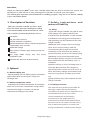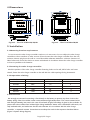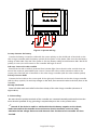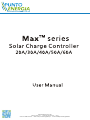
1
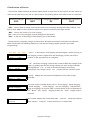
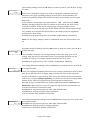
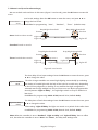
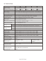
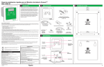
PUNTOENERGIA ITALIA SRL
Via Soccorso, snc - 71016 San Severo (FG) - ITALY
Tel & Fax: 0882.22.82.47 - Web: www.puntoenergiashop.it - e-mail: [email protected]
Contents
1 Description of function
P1
2 Safety Instructions and Waiver of Liability
P1
2.1 Safety
P1
2.2 Liability Exclusion
P1
3 Optional
P1
3.1 Remote display unit
P1
3.2 Remote temperature sensor
P1
4 Dimensions
P2
5 Installation
P2
5.1 Mounting location requirements
P2
5.2 Fastening the solar charge controller
P2
5.3 Preparation of wiring
P2
5.4 Connection
P2
5.5 Grounding
P3
6 Indication of Status
P4
7 Operating the solar charge controller
7.1 Factory Pre-Set configurations
7.2 Main Menu
P5
P5
P5
7.3 Menu Conf (System module settings)
P6
7.4 Menu Prog (System parameter settings)
P6
7.5 Menu Load (Load mode settings)
P8
7.6 Menu Logg (Inquiry of internal data logger)
P9
7.7 Example of configuration
P 10
7.7.1 Battery type
P 10
7.7.2 Reset to Factory Pre-Set Configuration
P 10
8 Safety Measures
P 11
8.1 Electronic Short Circuit Safety
P 11
8.2 Hardware Safety
P 11
8.3 Safety Features
P 11
9 Malfunctions and Errors
P 12
10 Technical Data
P 13
Dear Clients,
TM
Thanks for selecting the Max
series solar controller. Please take the time to read this user manual, this
will help you to make full use of many advantages the controller can provide your solar system.
This manual gives important recommendations for installing, program, using and so on. Read it carefully
in your own interest please.
2.Safety instructions and
waiver of liability
1. Description of function
With your new Max controller you own a stateof-the art device which was developed according
2.1 Safety
to the latest available technical standards. It comes
①The solar charge controller may only be used
with a number of outstanding features, such as:
in PV systems in accordance with this user
manual and the specifications of other modules
LCD display
manufacturers. No energy source other than a
One year's data memory
solar generator may be connected to the solar
12V/24V automatic recognition
External temperature sensor, make the temperature
compensation more accurate
charge controller.
②Batteries store a large amount of energy,
never short circuit a battery under all
Perfect EMC design
Many choices of battery type, working mode and
protection
Four stage PWM charge way: fast, boost,
equalization, float
Full automatic electronic protect function
circumstances. We strongly recommend
connecting a fuse directly to the battery to
protect any short circuit at the battery wiring.
③Batteries can produce flammable gases.
Avoid making sparks, using fire or any naked
flame. Make sure that the battery room is
ventilated.
④Avoid touching or short circuiting wires or
terminals. Be aware that the voltages on
3. Optional
special terminals or wires can be as much as
twice the battery voltage. Use isolated tools,
3.1 Remote display unit
Remote display unit can display system information,
failure information and one year's charge and
stand on dry ground, and keep your hands
dry.
⑤Keep children away from batteries and the
discharge data.
charge controller.
3.2 Remote temperature sensor
Acquisition the ambient temperature of the battery,
which can be accurate compensation charge values,
2.2 Liability Exclusion
The manufacturer shall not be liable for
standard wire length is 2 meters (can also be
damages, especially on the batter y,
customized according to user needs).
caused by use other than as intended or as
mentioned in this manual or if the
recommendations of the batter y
manufacturer are neglected. The
manufacturer shall not be liable if there
has been ser vice or repair carried out by
any unauthorized person, unusual use,
wrong installation, or bad system design.
Page1/13 Pages
4.Dimensions
164
Figure1:The size of Max20/30/40
Figure2:The size of Max50/60
5. Installation
5.1 Mounting location requirements
Do not mount the solar charge controller outdoors or in wet rooms. Do not subject the solar charge
controller to direct sunshine or other sources of heat. Protect the solar charge controller from dirt and
moisture. Mount upright on the wall on a non-flammable substrate. Maintain a minimum clearance of
10cm below and around the device to ensure unhindered air circulation. Mount the solar charge controller
as close as possible to the batteries.
5.2 Fastening the solar charge controller
Mark the position of the solar charge controller fastening holes on the wall, drill 4 holes and insert
dowels, fasten the solar charge controller to the wall with the cable openings facing downwards.
5.3 Preparation of wiring
Mode
Max.current
Diamete(mm²)
AWG
Max20
20A
10
8
Max30
30A
16
6
Max40
40A
16
6
Max50
50A
20
4
Max60
60A
20
4
5.4 Connection
We strongly recommend connecting a fuse directly to the battery to protect any short circuit at the
battery wiring. Solar PV modules create current whenever light strikes them. The current created varies
with the light intensity, but even in the case of low levels of light, full voltage is given by the modules. So,
protect the solar modules from incident light during installation. Never touch uninsulated cable ends, use
only insulated tools, and make sure that the wire diameter is in accordance with the solar charge
controller’s expected currents. Connections must always be made in the sequence described below
(Figure 3: System wiring diagram).
Page2/13 Pages
③
④
①
②
⑤ ⑥
Figure 3: System wiring
1st step: Connect the battery
Connect the battery connection cable with the correct polarity to the middle pair of terminals on the
solar charge controller (with the battery symbol). If the system is 12V, please make sure that the battery
voltage is within 10V~16V, else if the system is 24V, the battery voltage should between 20V~30V. If the
polarity is correct, the LCD screen on the controller will begin to show.
2nd step: Connect the solar module
Ensure that the solar module is protected from incident light. Ensure that the solar module does not
exceed the maximum permissible input current. Connect the solar module connection cable to the
correct pole of the left pair of terminals on the solar charge controller (with the solar module symbol).
3rd step: Connect loads
Connect the load cable to the correct pole of the right pair of terminals on the solar charge controller
(with the lamp symbol). To avoid any voltage on the wires, first connect the wire to the load, then to the
controller.
4th step: Final work
Fasten all cables with strain relief in the direct vicinity of the solar charge controller (clearance of
approx.10cm).
5.5 Grounding
Be aware that the positive terminals of the controller are connected internally and therefore have the
same electrical potential. If any grounding is required always do this on the positive wires.
!Remark: If the device is used in a vehicle which has the battery negative on the chassis,
loads connected to the controller must not have an electric connection to the car body,
otherwise the low voltage disconnect and electronic fuse functions of the controller are short
circuited.
Page3/13 Pages
6.Indication of Status
The two-line display indicates all present system values in short form on the top line, and the values are
without units (Volt, Amp, etc) due to a lack of space. The printing above each value serves as a reminder:
State of charge
SOC
Battery voltage
BAT
Charging currents
IN
Discharge currents
OUT
“SOC” means "state of charge" and indicates how much remaining capacity the battery still has. The
SOC is never 100% as due to technical reasons it is easier to indicate a two-digit number.
“BAT” shows the battery's actual voltage.
“IN” is the sum of the charging currents flowing into the battery.
“OUT” is the sum of discharge currents flowing out of the battery.
The second line constantly changes its information. All values and system information are indicated
alpha-numerically. The following displays can only be seen during regular operation (not while
programming).
OUT
“I accu” is the balance of all charging and discharging currents. As long as
88% 12.7 26
I accu = 8.3A
SOC
18
the charging current is higher than the discharging current, the value is
88% 12.7 26
I in = 26.4A
00
88% 12.7
15
BAT
IN
position, in the opposite case, it is negative.
“I in” shows the charging current at the moment. When the voltage of the
Temp =
00
battery is getting near the final charge voltage, the solar charge controller
will regulate the “I in” in order to protect the battery from being
overcharged. The charge current “I in” is lower than the module current.
“Temp” displays the environment temperature of the solar charge
controller.
25℃
The solar charge controller status such as "Fast charging", "Equal charging”,
88% 12.7 17
Boost charging
15
”Boost charging”, ”Float charging” and "No Charging” indicate which
stage of charging is in process. After a certain period of time of operation in
the “Boost” and “Equal” charging modes, the “Float” charge mode is
resumed.
88% 12.7
Load on
00
15
The content displays the current load state, “Load on” means the load has
been opened, “Load off” means the load is in a closed state.
Page4/13 Pages
7.Operating the solar charge controller
7.1 Factory Pre-Set configurations
With the factory pre-set configurations, the solar charge controller can be used in most applications
without further programming. On delivery, the controller is always set with these pre-set basic
configurations that enable immediate use of most typical solar systems after installation.
The solar charge controller can be reset to the factory pre-set configurations at any time with the Menu
CONF.
7.2 Main Menu
Set values and functions can be adjusted with the four control keys on the panel. By pressing the key
under the MENU, a Main Menu appears in the display – Conf (System module settings), Prog (System
parameter settings), Load (Load mode settings) and Logg (Inquiry of internal data logger). By pressing the
key below the corresponding abbreviation, you can enter the corresponding menu (Figure 4:
Programming Menu).
After entering the corresponding menu, the following actions can be set or viewed the appropriate
information:
①You can use the keys ▲▼ to select sub-menu, and press the OK button to enter the sub-menu.
②After entering the sub-menu, press ▲▼ to change the value.
③After setting, press the OK button to save the set value, and return to the previous menu level.
④Pressing the MENU key will exit the setting, bring the display back to the normal Main Menu.
!Note: 1.If you did not carry out any operation within 60s after entering the setup menu, the
controller will automatically exit the menu programming and the normal indication of running status
appears .
2.If there are no adjustments on an activated submenu value being changed, the display
indication jumps to the main menu and the adjustment in the open window is not stored or applicable.
Figure 4: Programming Menu
88% 12.7
26
I accu =
8.3A
OK
Conf
Logg
OK
Liquid
Nominal capacity
300Ah
Regulation
SOC
Factory adjust
Press OK+MENU
MENU
Load
Prog
Battery type
18
Float charge
MENU
Load control
13.7V
Boost charge
AUTO
Light on delay
14.5V
Equal charge
00:00
Light off delay
14.8V
D/N threshold
00:00
Night timer 1
3.0V
Disconnect
00:00
Night timer 2
30%
Reconnect
50%
Page5/13 Pages
00:00
Day
in
Ah
out
Total
KAh
100
80
in
1200
out
880
7.3 Menu Conf (System module settings)
In this menu, you can configure the system modules, including battery type, battery nominal capacity,
Battery type selection: Press the OK button to enter the menu, you may toggle
Battery type
Liquid
between ▲▼ Gel to liquid electrolyte.
Possibilities for programming: Liquid, Gel (Default: Liquid).
Battery nominal capacity: Press the OK button to enter the menu, press arrow keys ▲
Nominal capacity
300Ah
▼for changing the nominal capacity and press OK for entering the new value.
Possibilities for programming: 10Ah~9990Ah (Default: 300Ah).
Note: The nominal capacity must be consistent with the actual battery capacity
Low voltage protection mode (Soc or voltage control) settings: Press the OK button
Regulation
Soc
Factory adjust
Press OK+MENU
to enter the menu, and switch with the keys ▲ ▼ between SOC and Voltage.
Possibilities for programming: Soc, Voltage (Default: Soc).
Factory pre-set: Press the OK button to enter the menu, and press the
"OK + MENU" button simultaneously to reset the solar charge controller.
Note: If you press “OK+MENU”, all settings and values will be reset and the
execution will be confirmed by “Done”.
7.4 M enu P rog (System parameter settings)
In this menu you can set the charging parameters, Day/Nigh threshold, LVD and LVR data.
Press ▼ t o ent e r the menu.
Note: We have tried to insure that the values are limited within ranges that do not damage the battery
immediately. However, certain skills are needed as far as battery behaviour is concerned to prevent longterm damage or poor system performance. If you are unsure about any of these settings, please refer to
your authorised dealer or leave the pre-set configurations as they are.
Float charge
13.7V
Float voltage settings: Press the OK button to enter the menu, press ▲ ▼ to change
the value.
Note: The float voltage serves for maintaining the charge in the battery for long
periods and preventing self-discharge. This voltage should not be too high, since this
may lead to permanent gassing, which damages the battery. Maximum values are
stated on the battery data sheet of your battery. For most types of liquid battery, this
float value is 13.7V/27.4V.
Possibilities for programming: 13.0~14.5V/26.0V~29.0V (Default: 13.7V/27.4V).
Boost voltage settings: Press the OK button to enter the menu, press ▲ ▼ to change
Boost charge
14.5V
the value.
Possibilities for programming: 14.0~15.0V/28.0V~30.0V (Default: 14.5V/29.0V).
Page6/13 Pages
Equal voltage settings: Press the OK button to enter the menu, press ▲ ▼ to change
Equal charge
14.8V
the value.
Note: 1.The equalisation charging can only be adjusted for batteries with liquid
electrolyte, since high equalising voltages are harmful for sealed batteries. The
maximum equalising voltage value should be stated on the battery manufacturer's
data sheet.
2.This window is deactivated if you have selected “Gel” with the menu CONF.
3.Battery charging voltage is passed on directly to the loads by the solar charge
controller. Therefore, during equal charging, high charging voltages can be
programmed that may damage some loads. Please select this equal charge voltage
very carefully and compare the desired value to the battery and load (appliance)
manufacturers' data sheets.
Possibilities for programming: 14.0~15.5V/28.0V~31.0V (Default: 14.8V/29.6V).
Note: The fast charge voltage is fixed at 14.0V/28.0V, users do not have their own
set.
Day/Night threshold settings: Press the OK button to enter the menu, press ▲ ▼ to
D/N threshold
change the value.
3.0V
The controller recognizes day and night based on the solar array open circuit
voltage (only functional in street-light mode). This day/night threshold can be
modified according to local light conditions and the solar array used.
Possibilities for programming: 3.0~7.5V/6.0V~15.0V(Default: 3.0V/6.0V).
Low voltage disconnect settings: Press the OK button to enter the menu, press ▲ ▼
Disconnect
to change the value.
Soc = 30%
Note: 1.The difference between disconnect and reconnect threshold must be at least
20%. If you wish disconnect at higher state of charge you have to first adjust the
reconnect threshold (as per below) to 20 % above the desired disconnect threshold.
2.When you configure voltage regulation, you will find in this window voltage values
instead of SOC values for programming the disconnection voltage level.
The solar charge controller allows the smallest difference between reconnect and
disconnect is 0.8V/1.6V. If you want to program a high level for disconnection you
must first increase the reconnection level.
Possibilities for programming by SOC: 20%~70% (Default: 30%).
Possibilities for programming by voltage regulation:
11.0~12.5V/22.0~25.0V (Default: 11.1V/22.2V).
Low voltage reconnected settings: Press the OK button to enter the menu, press ▲ ▼
Reconnect
Soc = 50%
to change the value.
Possibilities for programming by SOC: 40%~90% (Default: 50%).
Possibilities for programming: by voltage regulation:
11.8V/23.6V~13.3V/26.6V (Default: 12.6V/25.2V).
Page7/13 Pages
7.5 Menu Load (Load mode settings)
We can set load mode and time in this menu (Figure 5: Load mode), press the OK button to enter this
menu.
Load mode settings: Press the OK button to enter the menu, and press ▲ ▼ to
Load control
AUTO
change the load mode.
Possibilities for programming: “Auto”, “Standard”, “Timer” (Default: Auto).
Day/Night threshold
Sunset
Auto: Dusk to dawn mode
Light on
Day/Night threshold
Sunrise
Dusk to dawn
Light off
Light off
Standard: Load on mode
Day/Night threshold
Day/Night threshold
Sunset
Sunrise
Timer: Double time mode
Night timer1
Light on
Night timer2
Light on
Light off
Light off
Light off
Figure5: Load mode
The time delay of load open settings: Press the OK button to enter the menu, press
▲ ▼ to change the value.
Light on delay
00:00
The solar charge controller can control night lighting automatically by evaluating
the density of outside light with the help of the solar PV module array. Depending
on the PV array alignment or shading, it may well be that night recognition is
activated even though twilight has not yet come to an end. By the programmable
time adjustment "Light on delay”, the night light switch-on may be shifted to a
later time.
Possibilities for programming: 00:00~02:00 (Interval 5min, Default: 00:00)
Light off delay
00:00
The delay time of load close settings: Press the OK button to enter the menu, press
▲ ▼ to change the value.
After setting "Light off delay" the light can remain on a period of time after dawn.
Possibilities for programming: 00:00~02:00 (Interval 5min, Default: 00:00).
Note: When the controller is set to "Standard", "Light on delay" and "Light off delay" have no effect
on it, but when the controller is set to "Auto" and "Timer", the delay time settings work.
Page8/13 Pages
Night time 1 settings: Press the OK button to enter the menu, press ▲ ▼ to change
the value.
Night timer 1
When the “Load control" is set to "Timer", "Night timer 1” is the first part light
00:00
on time when dusk coming. If set to "Auto" or "Standard", "Night timer 1" setting
is invalid.
Possibilities for programming: 00:00~09:00 (Interval 15min,Default: 00:00).
Night time 2 settings: Press the OK button to enter the menu, press ▲ ▼ to
change the value.
Night timer 2
When the “Load control" is set to "Timer", "Night timer 2” is the second part
00:00
light on time before dawn. If set to "Auto" or "Standard", "Night timer 2" setting
is invalid.
Possibilities for programming: 00:00~09:00 (Interval 15min,Default:
00:00).
7.6 Menu Logg (Inquiry of internal data logger)
Press MENU button to enter the menu, you can recall stored data values from today to the last 7 days,
at the same time you can view the accumulated value in and out of the system since the controller
installed.
From this menu window, you can read the actual daily value of amp-hours in and
Day
in
100
Ah
out
80
out of the system. Press OK to toggle the display from today’s current running data
values to the stored data values for the last 7 days. You can choose the desired day
to view with the arrow key ▲▼. The values can not be changed.
Note: "Day" simply stands for today and “Day 1”for the day before, “Day 2”
Day 1 in
Ah
out
120
90
means two days ago. When a new day of logging starts, the data for each of "Day”
to “Day 6” will be shifted to the previous day, i.e. the 7th day data will be replaced
with the data for the 6th day, 6th day replaced by 5th day, etc.
Total
KAh
in
1200
out
880
View the accumulated value in and out of the system since the controller installed,
this data can not be changed.
Note: The minimum value is 1KAh.
Note: All historical data will be deleted only when the device been reset to factory
settings.
Page9/13 Pages
7.7 Example of configuration
7.7.1 Battery type
By pressing the MENU key, you leave the online status display and go to the main menu. By pressing
the key below the corresponding abbreviation: Conf (System module settings), Prog (System parameter
settings) , Load (Load mode settings) and Logg (Inquiry of internal data logger), you can enter the
corresponding menu. In the case of this example you have to press the first key from left (labelled▲),
which is below the abbreviation Conf. This is how you get into the window for programming the Battery
type (Figure 6: Change the battery type).
Note: If you have pressed the wrong key by accident, press MENU to get back to the main menu and
start all over again.
7.7.2 Reset to Factory Pre-Set Configuration
In the previous section, it is described how to enter the window Battery type. The next window up
(press ▲) is for resetting the solar charge controller to the factory pre-set configuration (Factory adjust).
By pressing OK you can enter the Factory adjust window. The instruction to press the MENU key plus
the OK key appears immediately. Only by pressing both of these keys simultaneously will the factory
pre-set configurations be set. Then the second line shows "Done", means successfully restore the factory
settings (Figure 7: Reset to Factory Pre-Set configuration).
88% 12.7
26
I accu =
8.3A
OK
Conf
18
8.3A
OK
Conf
18
MENU
Load
Prog
Logg
OK
Logg
OK
MENU
MENU
Battery type
Battery type
OK
26
I accu =
MENU
Load
Prog
88% 12.7
OK
MENU
MENU
Factory adjust
Battery type
Liquid
OK
OK
MENU
Battery type
Factory adjust
Gel
OK
Press OK+MENU
MENU
OK
Battery type
Done
MENU
OK
Figure 6: Change the battery type
MENU
Factory adjust
Liquid
OK
MENU
MENU
Figure 7: Reset to Factory Pre-Set configuration
Note: 1. If you want to make sure that you have programmed correctly, press only OK and move
through all submenu items to check the values. Do not press the arrow keys while checking, or you will
change the values.
2. If you have programmed a wrong value, you will reach the window with the undesired value again
and press OK to change the value to the correct one by pressing the arrow keys▲▼.
Page10/13 Pages
8 Safety Measures
We urgently recommend the installation of a safety device on the battery pole in order to prevent
damage from short circuits between battery and the solar charge controller.
8.1 Electronic Short Circuit Safety
An electronic short circuit safety device is built into the solar charge controller and prevents both
destruction of the solar charge controller and the blowing of the safety fuse in case of short circuits on
the load terminals. The second line of the LCD display indicates this error as "Short circuit". After
elimination of this fault, the solar charge controller automatically switches back to normal operation after
about 60 seconds.
8.2 Hardware Safety
In addition to the electronic fuse device mentioned above, the solar charge controller has also been
protected by regular fuses which have been rated far beyond nominal currents to prevent false blowing
of the fuses during surges. The safety fuses are wired in parallel. In order to prevent fuses from blowing in
the case of high currents over a short period of time, a high value has been selected. Before the fuses
blow, the electronic safety fuse should prevent any excessive current flow.
8.3 Safety Features
Reverse polarity
Short circuit
Solar terminal
Battery terminal
Load terminal
Protected *1
Protected *1
Protected *2
Protected
Protected *3
Switches off immediately
Switches off with delay
Over current
Reverse Current
Over voltage
Protected
Max. 55V *4
Max. 40V
Switches off
Low voltage
Over temp
switches off the load if the temperature reaches the set value
*1 Controller can not protect itself in a 24V system when polarity of battery or solar is reversed.
*2 Controller can protect itself, but loads might be damaged.
*3 Battery must be protected by fuse, or battery will be permanently damaged.
*4 The solar panel voltage should not exceed this limit for a long time as voltage protection is done by a
varistor.
Warning: The combination of different error conditions may cause damage to the controller.
Always remove the error before you continue connecting the controller.
Page11/13 Pages
9 Malfunctions and Errors
The solar charge controller is protected against damage by various measures. Nevertheless, always take
utmost care in the proper operation of the solar charge controller. Short hints of the malfunctions are
indicated with the help of the LCD display. However, errors are only properly indicated in which the
system has been properly installed. If there are other malfunctions than the ones described below, please
check first of all if the solar charge controller has been connected to the battery, the module and the
loads correctly in the right polarity. Afterwards, check the safety fuses.
Error message The cause of the malfunction
Short circuit
Short circuit
Over current
The load current is too high and the
output is disconnected. Either the whole
consumption exceeds the max. discharge
currents or the max. Pulse currents were
exceeded by using high surge appliances.
Remedy
Switch off all loads. Remove the fault,
the controller will switch on load
automatically after 1 minute.
• Reduce loads or hours of operation of loads
to keep the battery from being discharged
Low voltage
Over heat
Battery has low capacity. To protect the
battery, all loads powered by the solar
charge controller will be disconnected.
deeply, or increase solar array to add
energy to the system.
• Connect all loads through the controller to
avoid strong discharge of the battery.
• It will restore only when the battery being
recharged and the voltage reaching the
reconnect voltage.
The maximum allowable temperature has
• Check the ventilation at the back heat
been exceeded. In order to reduce further
heat generation the loads are disconnected
sink and clean it if necessary.
• Protect the controller from direct sunshine.
• Reduce warming caused by appliances
near the controller.
• Reduce the loads or PV modules.
automatically. As soon as the solar charge
controller has cooled down, normal
operation will resume.
Over voltage
In particular, the recharge process through
back-up generators or chargers tied directly
to the battery causes battery voltages
higher than 16.5V/33.0V.
Disconnect external chargers, when the
batter y voltage is lower than 15.5V/31.0V
controller automatically restored.
LCD has no
• There is no voltage feed from the battery.
• current operating temperature is too high
• Check the battery connections and fuses.
• Check the working temperature.
• Reinstall the controller, disconnect
display
or too low above/below the operating
temperature, causing LCD not to function.
Page12/13 Pages
everything and connect it again in the
right order.
10. Technical Data
Max30
Mode
Max20
System voltage
12V/24V automatic recognition
30 A
Max40
40 A
Max50
Max60
50 A
60 A
Max solar or load current
20 A
Fast voltage
14.0V/28.0V(25℃)
Boost voltage
14.0~15.0V/28.0~30.0V ( Programmable), default : 14.5V/29.0V(25℃)
Equal voltage
14.0~15.5V/28.0~31.0V ( Programmable), default : 14.8V/29.6V (25℃)
Float voltage
13.0~14.5V/26.0~29.0V( Programmable), default : 13.7V/27.4V (25℃)
Day/Night threshold
3.0~7.5V/6.0~15.0V( Programmable), default : 3.0V/6.0V
Nominal capacity
10Ah~9990Ah( Programmable), default : 300Ah
Batter y type
Liquid, Gel( default : Liquid)
Temperature compensation
-4.17 mV/K per cell (Boost and Equal charge),
-3.33 mV/K per cell (Float charge)
LVD protection mode
Soc, Voltage(default : Soc)
Load disconnect
voltage
Load reconnect
voltage
Soc
20~70%( Programmable), default : 30%
Voltage
11.0~12.5V/22.0~25.0V( Programmable), default : 11.1V/22.2V
Soc
40~90%( Programmable), default : 50%
Voltage
11.8~13.3V/23.6~26.6V(Programable), default : 12.6V/25.2V
Load mode
Auto, Standard, Timer(default : Auto)
Light on delay
00:00~02:00 (Inter val 5min, Programmable), default : 00:00
Light off delay
00:00~02:00 (Inter val 5min, Programmable ), default : 00:00
Night time 1
00:00~02:00 (Inter val 15min, Programmable ), default : 00:00
Night time 2
00:00~02:00 (Inter val 15min, Programmable ), default : 00:00
Max solar voltage
55 V
Max batter y voltage
40 V
Dimensions/Weiht
127*189*47 / 550g
164*189*47 / 690g
Max wire size
25mm²
50mm²
Max power consumption
13.8mA
15mA
Temp erature Range
during operation
-10℃ ~ +60 ℃
Storage temperature
-25℃ ~ +80 ℃
Relative humidity
10%~90% Non-condensation
Case protection
IP32
Page13/13 Pages