1
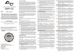
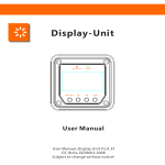
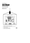
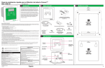
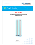
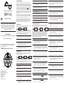
2. Synchronisation
In order to keep your battery monitor delivering accurate status information about your
battery, it is important to regularly synchronize your battery monitor with your battery. As
explained in the quick start guide, a synchronisation step is also needed before you can
actually use your battery monitor. During operation, the battery monitor automatically
indicates when a synchronisation is required, by displaying the message SYNCHRONIZE.
H1.6
Number of cycles.
H1.7
Number of synchronizations. This is the number of times the battery is fully
charged meeting the Auto-sync Functions.
H1.8
A synchronisation step means nothing more than performing a complete charge cycle on
your battery. A charge cycle will be considered complete when all Auto-sync parameters
F1.0, F1.1 and F1.2 (see chapter 5) are met. This typically means : when the battery
charger switches to float mode. By meeting these conditions, the battery is considered full,
which will be indicated by a flashing FULL message on the display. Besides this, the Stateof-charge readout will be set to 100% and the Amphour readout reset to 0Ah. The FULL
message will disappear when a key is pressed, or automatically, when the battery starts
discharging again.
High Precision Battery Monitor
SBM-02
Performing synchronisations regularly is also important to keep your battery healthy and to
increase it’s lifetime. You will notice that if you are often performing full charge cycles
yourselves, the battery monitor will most likely not display the SYNCHRONIZE message,
since the battery is already kept in good sync with the battery monitor.
Owner’s manual
GB
Besides automatic synchronisations based on meeting the Auto-Sync Functions, you can
also manually synchronize the battery monitor with your battery when you are sure your
battery is fully charged. This can be accomplished by pressing both < and > keys
simultaneously for three seconds. After these three seconds, the flashing FULL message
appears on the the display just like when it is automatically synchronized.
Thank you for purchasing a Studer Battery Monitor.
Please read this owner’s manual for information
about using the product correctly and safely.
Keep this owner’s manual close to the battery
monitor for future reference.
The Status menu is a read only menu that shows the battery monitor’s current status of
several items. This menu can be accessed by the following sequence:
[1x]
R. des Casernes 57 - CH-1950 Sion - Switzerland
St.1
Alarm Status. When multiple alarms are activated, use the < or > keys to browse
through the currently active alarms. When no alarms are activated, this item
displays “----“.
St.2
Days running. The number of days the battery monitor is operating to monitor your
battery. This item resets when a battery reset is executed (see Reset menu).
St.3
3
7
8
9
St.4
1. Charge battery indicator
2. Numeric value indicator field
3. Setup lock / Master lock indicator
4. Main battery or Auxiliary battery indicator
5. State-of-charge bar
6. Charging in progress indicator
7. Alarm activated indicator
8. Readout units
9. Synchronize indicator
10. Next value or Right key (>)
11. Menu key
12. Previous value or Left key (<)
H2.2
Number of Auxiliary battery low voltage alarms.
H2.3
Number of Main battery high voltage alarms.
H2.4
Number of Auxiliary battery high voltage alarms.
F2.5
F2.6
[2x]
Range : 0 - 300sec
Step size : variable
Minimum 'Alarm On' time. Minimum time that the alarm relay stays activated even
if the State-of-charge percentage has risen above the Low battery alarm Off
setpoint (F2.2). Function units are hours:minutes.
Range : 0:00 - 12:00
Step size : variable
Maximum 'Alarm On' time. Maximum time that the alarm stays activated even if
the the State-of-charge percentage is still below the Low battery alarm Off setpoint
(F2.2). The value “-:--“ indicates an unlimited time, and the relay will stay activated
until the State-of-charge percentage has risen above the Low battery alarm Off
setpoint (F2.2). Function units are hours:minutes
Default : -:- -
In the Function setup menu, your battery monitor can be adjusted to fit into your system.
Lots of parameters, called Functions, can be set according to your needs. This menu can
be accessed by the following sequence :
Range : 0:00 - 12:00 / -:- -
Step size : variable
Enable Low battery alarm / Use contact. Select “OFF” to disable the low battery
alarm. Select “[1]” to use the battery monitor's internal alarm relay. Select “[ ]1” to
“[ ]8” to use an external alarm contact (only for use with optional Alarm output
expander).
Default : [1]
Range : OFF / [1] / [ ]1..[ ]8
[1x]
When the Function setup menu is entered, you can use the < and > keys to browse
through the different Functions. By pressing the MENU key, the selected Function value
can be viewed. The < and > keys can now be used to change this value. Pressing the
MENU key again, will then step back to the Function menu. From any menu position, the
Normal Operating Mode can be accessed again by pressing the MENU key for 3 seconds.
This will also save any Function value changes to internal memory. When no keys are
pressed for 90 seconds while operating in the Function setup menu, the battery monitor
will automatically return to the Normal Operating Mode again without saving any Function
value changes.The following Functions are available :
F1.0
[1x]
When the History menu is entered, you can use the < and > keys to browse through the
different History items. By pressing the MENU key, the selected History item can be
viewed. Pressing the MENU key again, will then step back to the History menu. From any
menu position, the Normal Operating Mode can be accessed again by pressing the MENU
key for 3 seconds. The following History menu items are available :
Default : 10.5V
F3.1
F3.2
Step size : 0.1V
Charger's float current (Auto-sync parameter). When the charge current is below
this percentage of the battery capacity (see Function F5.0), the battery will be
considered as fully charged. Make sure this Function value is always greater than
the minimum current at which the charger maintains the battery or stops charging.
Step size : 0.1%
Auto-sync time (Auto-sync parameter). This is the time the Auto-sync parameters
F1.0 and F1.1 must be met in order to consider the battery as fully charged.
Default : 240sec
F1.3
Range : 0.5 - 10.0%
Range : 5 - 300sec
Range : 0 - 99%
F3.4
H1.0
Average discharge in Ah. This number will be recalculated after each
synchronization.
H1.1
Average discharge in %. This number will be recalculated after each
synchronization.
Time remaining averaging filter. Specifies the time window of the moving
averaging filter. There are three settings, where setting 0 gives the fastest Time
remaining readout response and setting 2 the slowest. The best setting will
depend on the type of battery load and your personal preference.
H1.2
Deepest discharge in Ah.
Default : 1
H1.3
Deepest discharge in %.
H1.4
Total Amphours removed. The total number of Amphours removed from the
battery. When exceeding 10000Ah, the units are kAh and the value displayed
must be multiplied by 1000.
F1.5
Range : -20..+50°C / AU
Range : 0 - 2
F4.0
Step size : 1°C
F2.1
H1.5
Total Amphours charged. The total number of Amphours charged to the battery.
These Amphours are not compensated by the Charge Efficiency Factor (CEF).
When exceeding 10000Ah, the units are kAh and the value displayed must be
multiplied by 1000.
Range : 0 - 99%
Range : 8.0 - 33.0V
Range : 0 - 300sec
Step size : variable
Step size : 1%
Step size : 0.1V
Range : OFF / [1] / [ ]1..[ ]8
Main battery high voltage alarm On. When the Main battery voltage rises above
this value, the message “Hi” will appear on the display and the selected alarm
relay will be activated (depending on F4.2).
F4.1
F4.2
Range : 10.0 - 35.0V
Step size : 0.1V
Main battery high voltage alarm Delay. This is the time the Main battery high
voltage alarm On condition, F4.0, must be met before the alarm is activated.
Default : 5sec
Low battery alarm On (Volts). When the battery voltage has fallen below this
value, the alarm relay will be activated (depending on F2.6).
Default : 10.5V
Step size : 0.1V
Enable Auxiliary battery low voltage alarm / Use contact. Select “OFF” to disable
the Auxiliary battery low voltage alarm. Select “[1]” to use the battery monitor's
internal alarm relay. Select “[ ]1” to “[ ]8” to use an external alarm contact (only for
use with optional Alarm output expander).
Default : 16.0V
Step size : 1
Low battery alarm On (% SOC). When the State-of-charge percentage has fallen
below this value, the alarm relay will be activated (depending on F2.6).
Default : 50%
Range : 8.0 - 33.0V
F4 : HIGH VOLTAGE ALARM SETTINGS
F2 : LOW BATTERY ALARM SETTINGS
F2.0
Range : OFF / [1] / [ ]1..[ ]8
Step size : 1%
Battery temperature. In this Function the average battery temperature can be
adjusted. The value AU enables the automatic temperature measurement,
provided that an external temperature sensor is connected to the battery monitor.
Also the temperature readout in the Normal Operating Mode is enabled.
Default : +20°C
Step size : variable
Auxiliary battery low voltage alarm Delay. This is the time the Auxiliary battery low
voltage alarm On condition, F3.3, must be met before the alarm is activated.
Default : OFF
F1.4
Range : 0 - 300sec
Auxiliary battery low voltage alarm On. When the Auxiliary battery voltage falls
below this value, the message “Lo” will appear on the display and the selected
alarm relay will be activated (depending on F3.5).
Default : 10sec
F3.5
Step size : 0.1V
Enable Main battery low voltage alarm / Use contact. Select “OFF” to disable the
Main battery low voltage alarm. Select “[1]” to use the battery monitor's internal
alarm relay. Select “[ ]1” to “[ ]8” to use an external alarm contact (only for use with
optional Alarm output expander).
Default : 10.5V
Step size : variable
Discharge floor. This is the reference point at which the battery needs to be
recharged. When the State-of-charge percentage falls below this value the Charge
battery indicator starts flashing while the time remaining readout shows 0:00 and
the State-of-charge bar is empty.
Default : 50%
F3.3
Range : 8.0 - 33.0V
Main battery low voltage alarm Delay. This is the time the Main battery low voltage
alarm On condition, F3.0, must be met before the alarm is activated.
Default : OFF
F1.2
[1x]
Range : 8.0V - 33.0V
Main battery low voltage alarm On. When the Main battery voltage falls below this
value, the message “Lo” will appear on the display and the selected alarm relay
will be activated (depending on F3.2).
Default : 10sec
Charger's float voltage (Auto-sync parameter). This value must be equal to your
battery charger’s float voltage. which is the last stage of the charging process. In
this stage the battery is considered full.
Default : 13.2V
Charge Efficiency Factor (CEF). The charge efficiency factor used by the battery
monitor. Depending on the value set in Function F5.6, this item displays the
automatically calculated CEF or the manually set CEF.
[3 sec]
F3.0
F1 : SYSTEM PROPERTIES
Default : 2.0%
10
11
F2.4
Default : 0:00
H1 : BATTERY HISTORY :
Battery monitor
SBM-02
12
Number of Main battery low voltage alarms.
The History menu is a read only menu that shows the battery monitor’s History data.
History data are special events that are stored in internal memory. This menu can be
accessed by the following sequence :
6
1
H2.1
Days since last synchronized. The number of days the battery monitor has not
been synchronized. This item resets when the battery monitor is synchronized or
when a battery reset is executed (see Reset menu).
4. History menu
2
Number of Low Battery alarms.
Step size : 1%
Low battery alarm On delay time. This is the time the Low battery alarm On
conditions, F2.0 and F2.1, must be met before the alarm is activated.
Default : 10sec
H2.0
F1.1
1. SBM-02 display and control overview
4 5
F2.3
Range : 1 - 100% / FULL
F3 : LOW VOLTAGE ALARM SETTINGS
http://www.studer-innotec.com
Before proceeding with this owner’s manual, please make
sure you have carefully read the enclosed installation and
quick start guide as well!
Low battery alarm Off (% SOC). When the State-of-charge percentage has risen
above this value and the alarm relay was activated, the alarm relay will deactivate
again. When “FULL” is selected, the alarm relay is deactivated when the Autosync parameters are met.
Default : 80%
H2 : ALARM HISTORY
[3 sec]
When the Status menu is entered, you can use the < and > keys to browse through the
different status items. By pressing the MENU key, the selected status item can be viewed.
Pressing the MENU key again, will then step back to the Status menu. From any menu
position, the Normal Operating Mode can be accessed again by pressing the MENU key
for 3 seconds. The following Status menu items are available :
Studer Innotec
Number of full discharges. The number of times the battery has been fully
discharged reaching a State-of-charge of 0.0%.
5. Function setup menu
3. Status menu
[3 sec]
F2.2
Range : 0 - 300sec
Step size : variable
Enable Main battery high voltage alarm / Use contact. Select “OFF” to disable the
Main battery high voltage alarm. Select “[1]” to use the battery monitor's internal
alarm relay. Select “[ ]1” to “[ ]8” to use an external alarm contact (only for use with
optional Alarm output expander).
Default : OFF
Range : OFF / [1] / [ ]1..[ ]8
F4.3
Auxiliary battery high voltage alarm On. When the Auxiliary battery voltage rises
above this value, the message “Hi” will appear on the display and the selected
alarm relay will be activated (depending on F4.5).
Default : 16.0V
F4.4
Step size : 0.1V
Auxiliary battery high voltage alarm Delay. This is the time the Auxiliary battery
high voltage alarm On condition, F4.3, must be met before the alarm is activated.
Default : 5sec
F4.5
Range : 10.0 - 35.0V
Range : 0 - 300sec
F6.6
F6.7
Range : OFF / [1] / [ ]1..[ ]8
Battery capacity. Your Main battery’s capacity in Amphours (Ah).
Default : 200Ah
F5.1
Range : 20 - 9990Ah
F6.8
Step size : variable
Nominal discharge rate (C-rating). The discharge rate (in hours) at which the
battery manufacturer rates your battery’s capacity.
Default : 20h
Range : 1 - 20h
F5.3
Step size : 0.01%cap/°C
Peukert's exponent. The Peukert’s exponent represents the effect of reducing
battery capacity at higher discharge rates. When the Peukert value of your battery
is unknown, it is recommended to keep this value at 1.25. A value of 1.00 disables
the Peukert compensation.
Default : 1.25
F5.5
Range :
OFF / 0.01 - 1.00
Range : 1.00 - 1.50
Step size : 0.01
Self-discharge rate. This is the rate at which the battery loses capacity by itself,
even when it is not used. The unit of this value is percent capacity per month at
the Nominal temperature (F5.2). The setting “OFF” disables self-discharge
compensation.
Default : 3.0%/month Range : OFF / 0.1 25.0%/month
Range : 0 / 1 / 2 / 3
Setup lock. When set to “ON”, all functions (except this one) are locked and
cannot be altered. The Reset menu is also locked.
Default : OFF
Range : OFF / ON
Step size : 1°C
Temperature coefficient. This is the percentage that your battery’s capacity
changes with temperature. The unit of this value is percent capacity per degree
Celsius. The setting “OFF” disables temperature compensation.
Default :
0.50%cap/°C
F5.4
Range : 0 - 40°C
Communication mode. This Function is used to configure the data output mode.
There are four data output modes :
Mode “0” : SBM-02 (broadcasting)
Mode “1” : SBM-02 (request mode)
Mode “2” : SBM-01 compatibility mode (broadcasting)
Mode “3” : SBM-01 compatibility mode (request only)
Default : 0
Nominal temperature. The temperature at which the battery manufacturer rates
your battery’s capacity.
Default : 20°C
Range : 0 / 1
Step size : 1h
F6.9
F5.2
Range : °C / °F
Auxiliary input mode. This Function is used to configure the VA input terminal on
the rearside of the battery monitor, and can be set in two modes. In mode “0”, the
VA input operates in normal voltage measurement mode. In mode “1”, the VA
input can be used to control the backlight. In this mode, the backlight is switched
ON at an input voltage higher than 2V and switched OFF again if the voltage is
below 1V.
Default : 0
Step size : 0.1%/month
6. Reset menu
In the Reset menu, you can reset a number of items of your battery monitor This menu
can be accessed by the following sequence :
[3 sec]
State-of-charge and/or time-to-go readout
not accurate
Range : 1-1 / 1-5 / 1-10
Temperature unit selection. Enables selection between degrees Celsius (°C) and
degrees Fahrenheit (°F) in the temperature readout.
Default : °C
F5 : ‘MAIN’ BATTERY PROPERTIES
F5.0
Voltage prescaler. This Function is only important when an optional voltage
prescaler is installed on the battery monitor. All voltage related Functions are
linked to this Function F6.5. Always keep this Function set to “1-1” when no
prescaler is installed!
Default : 1-1
Step size : variable
Enable Auxiliary battery high voltage alarm / Use contact. Select “OFF” to disable
the Auxiliary battery high voltage alarm. Select “[1]” to use the battery monitor's
internal alarm relay. Select “[ ]1” to “[ ]8” to use an external alarm contact (only for
use with optional Alarm output expander).
Default : OFF
F6.5
[3x]
[1x]
When the Reset menu is entered, you can use the < and > keys to browse through the
different reset items. By pressing the MENU key, the selected reset item can be viewed.
The default value for all reset items is “OFF”. To actually reset the selected item, use the <
and > keys to change the value from “OFF” to “ON”. Pressing the MENU key again, will
step back to the Reset menu. All reset items set to “ON” will only be reset once the Normal
Operating Mode is accessed again by pressing the MENU key for 3 seconds. The
following Reset menu items are available :
- Check if all current is flowing through the
shunt (the negative terminal of the battery
may only contain the wire going to the
battery-side of the shunt!).
- Current sense leads from the shunt are
reversed.
- Check all Battery properties Functions (F5)
- Check if battery monitor is synchronized.
Display returns '- - - -' in temperature
readout
- Connection with temperature sensor is lost.
Check for failed connections and/or cable
damage.
Battery voltage readout is highly inaccurate
- Check prescaler setting in Function F6.5
Reset alarms. Use this reset item to reset or ignore all current alarms.
rSt.b
Reset Battery status. Use this reset item to reset your current battery status (CEF,
State-of-charge and battery history). You can use this reset item after you have
installed a fresh battery of the same specifications as the previous one.
Charge Efficiency Factor (CEF). CEF is the ratio between the energy removed
from a battery during discharge and the energy used during charging to restore
the original capacity. It is recommended to keep keep this value at “AU” (automatic
calculation). The setting “100” disables charge efficiency compensation.
Default : AU
Range : 50 - 100% / AU
Step size : 1%
F6 : BATTERY MONITOR PROPERTIES
F6.0
Reset Functions. This reset item can be used to reset all Function values to
factory default values.
This warranty is void if the product has suffered any physical damage or alteration, either
internally or externally, and does not cover damage arising from improper use1) or from use
in an unsuitable environment.
F6.1
Shunt Amp Rating. This Function is linked to F6.2 and represents the Amp rating
of your shunt at the given voltage indicated by F6.2. Included with your battery
monitor is a 500Amp/50mV shunt, meaning that at 500A flowing through the
shunt, a voltage of 50mV is generated across the small ‘Kelvin’ screw terminals of
the shunt. This voltage will be used by the battery monitor to measure the amount
of current.
Default : 500A
F6.2
Parameter
Supply voltage range
Supply current 1) :
9..35VDC
@Vin=24VDC
Input voltage range (auxiliary battery)
Input current range2)
Range : OFF / 5…300 / ON / AU
Step size : variable
Alarm contact polarity. Enables selection between a normally open (NO) or
normally closed (NC) contact.
Default : NO
Range : NO / NC
9mA
2..35VDC
0..35VDC
-9999..+9999A
Battery capacity range
Readout resolution :
7mA
20..9990Ah
-20..+50°C
voltage (0..35V)
± 0.01V
current (0..200A)
± 0.1A
Remedy or suggestion
amphours (200..9990Ah)
± 1Ah
- Check monitor- and battery side
connections.
- Make sure the inline fuses are installed
and not blown.
- Check battery voltage. Battery might be
flat. Vbatt must be >8VDC.
- Try to restart the monitor by removing /
placing the fuses again.
state-of-charge (0..100%)
± 0.1%
No changes can be made in the Function
setup
“CHARGE” or “SYNCHRONIZE” keeps on
flashing
time-to-go (0..24hrs)
time-to-go (24..240hrs)
temperature (-20..50°C)3)
Voltage measurement accuracy
- Charge battery full (synchronize your
battery with the monitor)
- Check the Auto-sync parameters in
Functions F1.0, F1.1 and F1.2 for possible
wrong settings.
± 1minute
± 1hr
± 0.5°C
± 0.3%
Current measurement accuracy
± 0.4%
Dimensions :
frontpanel
ø 64mm
body diameter
ø 52mm
total depth
- Check if the setup-lock is OFF (Function
F6.9)
- Your SBM-02 might be locked by the
superlock. Ask the installer for the
password to unlock the monitor using the
PC-link.
The above product is in conformity with the following harmonized standards :
EN61000-6-3: 2001
EMC - Generic Emissions Standard
EN61000-6-2: 2005
EMC - Generic Immunity Standard
SBM-02
Problem
Range : 50 / 60mV
Backlight mode. Represents the duration of backlight activation in seconds after
key-press. The backlight can also be set to be always “ON” or always “OFF”.
Function setting “AU”, activates the backlight automatically when charge /
discharge current exceeds 1Amp or when a key is pressed.
Default : 30sec
F6.4
Step size : variable
Shunt milliVolt Rating. This Function represents the milliVolt rating of your shunt at
the given current indicated by F6.1. The battery monitor supports 50mV and 60mV
shunts.
Default : 50mV
F6.3
Range : 10 - 9000A
BATTERY MONITOR
SBM-02
9. Technical specifications
The monitor doesn't operate (no display)
- Check the wiring for corrosion and / or
loose contacts.
- Battery might be flat or defective.
:
:
Examples of improper use are :
- too high input voltage applied
- wrong shunt connection
- applying battery voltage to shunt input
- mechanically stressed enclosure or internals due to harsh handling and/or incorrect
packaging
- contact with any liquids or oxidation caused by condensation
± 1A
The monitor resets all the time
Declares that the following products :
1)
± 0.1Ah
- Current sense leads from the shunt are
reversed. Check the installation guide.
R. des Casernes 57
CH-1950 Sion
Switzerland
Since Studer cannot control the use and installation (according to local regulations) of their
products, the customer is always responsible for the actual use of these products. Studer
products are not designed for use as cricital components in life support devices or
systems, that can potentially harm humans and/or the environment. The customer is
always responsible when implementing Studer products in these kind of applications.
Studer does not accept any responsibility for any violation of patents or other rights of third
parties, resulting from the use of the Studer product. Studer keeps the right to change
product specifications without previous notice.
amphours (0..200Ah)
Current readout gives wrong polarity
(positive current instead of negative when
discharging)
:
This warranty will not apply where the product has been misused, neglected, improperly
installed or repaired by anyone other than Studer. Studer is not responsible for any loss,
damage or costs arising from improper use, use in an unsuitable environment or improper
installing, setup and malfunctioning of the product.
7. Troubleshooting guideline
Default : x.xx
ADDRESS
Conforms to the requirements of the following Directives of the European Union :
EMC Directive 2004/108/EC
RoHS Directive 2002/95/EC
current (200..9999A)
Firmware version. Displays the firmware version of the battery monitor (read only).
Studer Innotec
Studer warrants this product to be free from defects in workmanship or materials for 24
months from the date of purchase. During this period Studer will repair the defective
product free of charge. Studer is not responsible for any costs of the transport of this
product.
Input voltage range (main battery)
rSt.F
:
PRODUCT TYPE
MODEL
Operating temperature range
F5.6
MANUFACTURER
8. Warranty conditions
@Vin=12VDC
rSt.a
10. Declaration of conformity
Weight
Shunt dimensions :
footprint
height
weight
Protection class
Accessories
79mm
95grams
45 x 87mm
17mm (base) / 35mm (M8 screws)
145 grams
IP20 (frontpanel only IP 65)
- SBM-CAB-20, Conn.kit 20m
- SBM-TEMP-20, Temp.kit 20m
- SBM-COM, Communication kit RS232
- SBM-PS-01, Voltage prescaler 1:5
Note: the given specifications are subject to change without notice.
1)
Measured with backlight and alarm relay turned off.
2)
Depends on selected shunt. With standard delivered 500A/50mV shunt (350A
continuous), the range is limited to -600..+600A.
3)
Only available when optional temperature sensor is connected.
Studer SBM-02 Manual Rev2e / Printed in The Netherlands