1
IPv6 in Embedded Micro-controllers
COMP420Y Final Report
Student: Jeremy Stringer (0023109)
Supervisor: Richard Nelson
© J. Stringer 2003
Table of Contents
1. INTRODUCTION .........................................................................................4
1.1. Specification...........................................................................................................4
2. HARDWARE................................................................................................5
2.1. Introduction...........................................................................................................5
2.2. Problem Statement................................................................................................5
2.3. Component Decisions............................................................................................6
2.4. Direct Memory Access (DMA) Support..............................................................6
2.5. Implementation .....................................................................................................7
2.6. Implementation Issues ..........................................................................................8
3. HARDWARE/SOFTWARE INTERFACE.....................................................9
3.1. Problem Statement................................................................................................9
3.2. The Zero-Copy Paradigm ....................................................................................9
3.3. The Memory Recycle Algorithm .........................................................................9
3.4. The Memory Recycle Algorithm – Problems and Solutions...........................11
3.4.1. Deadlock detection and buffer flushing.........................................................14
3.4.2. Dedicated Privileged buffers..........................................................................14
3.4.3. Packet-Assemble-Instructions (PAI) Queues ................................................14
3.5. Multi-Buffering ...................................................................................................16
3.6. Multicast Reception ............................................................................................16
3.7. Differences between the CS8900A and the RTL8019AS.................................17
3.8. Ethernet Driver Structure and Operation........................................................18
Non Hardware-Specific Functions...........................................................................18
3.8.1. Initialisation Code..........................................................................................18
3.8.2. The Interrupt Service Routine (ISR)..............................................................19
3.9. Implementation Issues ........................................................................................23
4. SOFTWARE ..............................................................................................24
4.1. Problem Statement..............................................................................................24
4.2. Stateless Address Auto-configuration ...............................................................24
2
4.3. Duplicate Address Detection ..............................................................................25
4.4. Router Discovery.................................................................................................25
4.5. Neighbour Discovery ..........................................................................................25
4.6. IPv6 to Ethernet Address Mapping...................................................................26
4.7. IPSec.....................................................................................................................26
4.8. Implementation Issues ........................................................................................26
5. TESTING ...................................................................................................27
5.1. Problem Statement..............................................................................................27
5.2. Testing Setup .......................................................................................................27
5.3. Testing Results ....................................................................................................27
6. CONCLUSION...........................................................................................28
7. REFERENCES ..........................................................................................29
8. BIBLIOGRAPHY .......................................................................................30
3
1. Introduction
This report concerns itself with the practical issues in implementing the Internet
Protocol Version 6 (IPv6) in embedded systems.
IPv6 is the next generation of the Internet Protocol, the protocol that all computers use
to communicate across the Internet. It supports features such as auto-configuration
that are ideal for Low Cost Network Appliances (LCNAs) by making them easier to
configure and deploy. One problem however is that IPv6 has considerably more
complexity than IPv4 in some areas, and as such, presents practical difficulties in its
implementation in embedded systems.
An embedded system is a small computer system literally ‘embedded’ into an
appliance or piece of machinery. Embedded systems are typically very limited in the
amount of memory and processing power that they have, and often do not even run
Operating Systems.
For this project I have built a small embedded system that is typical of an low cost
network appliance and ported and modified an existing IPv6 stack to it. The existing
IPv6 stack that was used communicated via a slow serial line and needed to be tested
on Ethernet – hence I wrote an Ethernet driver, and implemented specific
functionalities required for Ethernet operation, such as Neighbour Discovery and
Auto-configuration, as detailed in later sections. The initial software development
was done on a development board on loan from Mitsubishi in order to parallelise the
software and hardware development, and as such two Ethernet drivers were written,
as the hardware that was produced used a different chipset from the development
board Ethernet card. The purpose of this project was to find the practicalities (and
limits) of implementing IPv6 in an embedded system by building a ‘typical’ system
and attempting to modify an existing IPv6 stack to run on it.
The problems that have been tackled in this project fit into four main categories – the
design and construction of the hardware, the data transfer strategy and interfacing of
the stack to the hardware, the IPv6 stack development, and the testing of work
completed. The following report is structured as such.
1.1. Specification
IPv6 is still a protocol under development, and work is still going on to standardise
the minimum node requirements. Work has been done by the TACA (Tiny software
and system Architecture for non-Computer Appliances) Project to define the
minimum requirements for LCNAs (Low Cost Network Appliances) (Okabe.,
Sakane., Inoue., Ishiyama., Esaki., 2003), but that effort has since been absorbed into
the main IPv6 Node requirements document (Loughney., 2003), which defines what
an IPv6 node must implement in order to be considered IPv6 compliant. The
elements of the node requirements document that this project is compliant with are
listed under testing.
4
2. Hardware
2.1. Introduction
In this project two sets of hardware have been used – one set was a development
board with add-on Ethernet card, kindly loaned by Mitsubishi, and the other set of
hardware was the hardware designed specifically for this project. The decision was
made to construct hardware for the project in order to provide a ‘typical system’ – one
that matched the approximate specifications of the target system family, but was also
engineered for the optimal performance that a system of this type would be
engineered for.
An important part of implementing networking on such a limited platform is to make
maximum use of hardware to support the software implementations – for instance the
common Network Interface Controller used in the final hardware contains 16KB of
on-board buffer RAM (Realtek., 2001), and much more control on how it is used, as
opposed to the 4KB buffer RAM available on the add-on card (Cirrus Logic., 2001).
The hardware designed in this project has the capability of providing better
performance in several areas while being a very similar computing platform to the
development board. It was also projected at the beginning of the project that more
system resources may have been needed, in terms of RAM or a processor upgrade, to
determine the minimum requirements for such a system, could it not be implemented
on the development board, but this turned out not to be the case.
The development board was also however a critical part of the project – although the
use of two different Ethernet chips required the development of two Ethernet drivers,
the use of the development board was critical in both an early understanding of the
issues involved, and in the parallelisation of the hardware and software development.
2.2. Problem Statement
The notion of an ‘embedded system’ is a vague one, in terms of processing power and
memory capacity, with such systems including 4 MHz, 8-bit, micro-controllers to 300
MHz Celeron systems such as found in Biscuit PCs. Clearly, the upper end of this
scale is not what this project is concerned with – a 300 MHz Celeron certainly has the
processing power to manage IPv6. It is also clear that the lower end of the scale is not
relevant either – a 4 MHz 8 bit micro-controller would lack the sheer processing
power to even receive 10 Mbit Ethernet at full rate.
The first decision that was made was to design the hardware with a common
embedded micro-controller that runs at approximately the 20 MHz mark. This means
that there is sufficient processing power available to manage the Ethernet
communication, but also that the device will be close in specification to those
employed in such applications as office equipment or consumer network appliances
(Mitsubishi 2001).
The second decision was in order to satisfy the memory requirements for both RAM
and ROM within the system. The amount of RAM needed was estimated to be at a
minimum of 10 KB, with preference for more. The reasoning for this is that the
existing stack already uses 10 KB of RAM, and with the addition of Ethernet
5
functionality, the memory requirements increase. The amount of ROM was estimated
to be a minimum of approximately 10KB. This figure allows for the code size of the
existing stack, with some room to spare. Given that in most embedded microcontrollers the ROM capacity far exceeds the RAM capacity, this metric was not
important in selecting a micro-controller (Renesas., 2003).
In addition to the requirements above, the decision was made to use a micro-controller
with DMA support in order to relieve CPU contention, as the transfer of Ethernetscale amounts of data amounts to a considerable waste of processor power in copying.
The system also needed a Network Interface Controller (NIC) in order to interface the
micro-controller to the network. The NIC was specified to be a common 10 Mbit
controller, as 10 Mbit Ethernet is both common and compatible with a large amount
of network equipment such as hubs and routers. In addition, 10 Mbit Ethernet
presents a reasonable amount of data to the micro-controller – a 100 Mbit NIC would
require computing power far in excess of what the target micro-controller provides.
2.3. Component Decisions
The Mitsubishi M30803 processor was selected for the hardware implementation. It
is part of the M16C family of micro-controllers which scale from 5 MIPS up to 32
MIPS in CPU power, while still remaining reasonably compatible, enabling the
replacement of the micro-controller should the selected micro-controller prove
insufficient for the task. The M30803 runs at 20MHz, which is the same as the 10
Mbit Ethernet NICs, and features 20 KB RAM and 256 KB of ROM – hence
satisfying or exceeding memory and processing power requirements. It has a DMA
controller, and features In-System-Programming (ISP), a technology that allows the
internal ROM to be programmed without removing the micro-controller from the
circuit. It is also a micro-controller aimed at the household appliance and office
equipment market, which means that it is well-suited as exemplar of the target system
family (Mitsubishi., 2003).
The Realtek RTL8019 was selected for the Ethernet interface, as it is a cheap and
common NIC, and it supports both 10 Mbit Ethernet and the ISA bus interface
standard, which makes it easier to interface to the micro-controller, as opposed to
more recent NIC designs which utilise the PCI bus common in modern PCs. In
addition to these considerations, the hardware structure of the RTL8019 supports
solutions to some Hardware/Software interface difficulties involving low memory and
the Memory Recycle Algorithm. This is detailed under later sections.
2.4. Direct Memory Access (DMA) Support
Direct Memory Access is important in an embedded system running a high-bandwidth
device such an NIC because it allows more efficient copying, and it allows the
copying to occur with minimal CPU intervention, in parallel with other tasks. For a
comparison, in the M16C series, at a minimum, a 16-bit transfer from an external
memory area to the internal RAM, actuated by a CPU instruction, will take two cycles
to execute, depending on factors such as the number of bytes in the CPU instruction
queue buffer (Mitsubishi., 2001 C). A 16-bit DMA transfer under the same
conditions will take a guaranteed two cycles, without overhead needed for loop
control or incrementing of addresses (Mitsubishi., 2001 A). In the best case, even
6
when utilising such optimisation techniques as loop unrolling, DMA as a mechanism
for data transfer is faster, and hence more efficient.
The efficiency is clearly critical when the amount of data to be transferred and
processed is taken into account. An Ethernet link rate of only 10 Mb could at
maximum produce in the order of 1.25 MB per second of data each way (full-duplex
operation). This means that the micro-controller should optimally be capable of
transferring a full 2.5 MB of data across its external data bus, at a speed of 1.25
million 16-bit transfers/second. When the differing amounts of cycles for reading
versus writing are taken into account, this operation will occupy a maximum of 16%
CPU time (using DMA) – close to a sixth of the CPU time available. If other
operations such as measurement or data processing are also time-critical, then this
means that the time must be efficiently multiplexed – the means to which this is
possible by software alone are limited, if existent, highlighting a need for hardware
parallelism.
The DMA controller in the M30803 micro-controller works by what is called ‘the
cycle steal’ method (Mitsubishi, 2001). This means that when there are DMA
transfers in progress, CPU cycles are shared between each DMA channel and the CPU
in a round-robin manner, providing the data transfer/program execution parallelism.
The word transfer count and the addresses to transfer to and from are also loaded, but
in order for a single word transfer to occur, a selectable trigger signal must be
activated (Mitsubishi., 2001 A). In the case of the demonstration board, there was no
available trigger signal from the NIC to activate these, so the DMA transfers were
triggered from a high-speed internal clock. In the final hardware design, the DMA
transfers were set to trigger from the IOCS16B signal. The IOCS16B signal is an ISA
bus signal that is triggered on a word transfer, hence allowing the DMA controller to
effectively self-trigger. The timing of the trigger is not critical – the CPU schedules
the DMA transfer to occur at the next available moment, although if two requests are
made before the hardware has the opportunity to react, only one transfer will take
place (Mitsubishi, 2001). This is not an issue in the design.
2.5. Implementation
The Printed Circuit Board (PCB) was implemented using a two-layer design, as that
was determined to be the minimum number of layers necessary in order to be able to
complete the design. Two layers was considered the minimum, especially when noise
considerations were taken into account – two layers allowed a reasonable area of one
layer to be used for a ground plane as well as providing for the routing considerations
in connecting two 100-pin chips. The costs of manufacture was also a factor in the
design – a two layer board is considerably cheaper than boards with more layers, as it
can be manufactured in New Zealand. Quotes were obtained from multiple
manufacturers confirming this. Implementing the design in two layers was of
moderate difficulty, as the design parameters of the PCB manufacturer were larger
than manufacturers offering multi-layer board manufacture, so some parts were
changed, and the board was increased in size.
The board was designed for hardware-triggered DMA operation as described above,
and featured two serial ports, for In-System-Programming, a method by which the
Flash ROM in the micro-controller is written via serial port, debugging via monitor,
and simultaneous program output. The micro-controller units were sourced from
7
Mitsubishi in Australia, and arrived promptly. The NICs were sourced from
Cornelius Consulting in Germany, as Realtek does not provide samples, and only sells
in bulk. The PCBs were manufactured in Auckland by Circuit Graphix Ltd.
2.6. Implementation Issues
Due to the timeframe of the project, and a miscalculation on time available, the PCB
design was completed under intense time pressure – pressure that was increased when
the RTL8019s failed to come in the two weeks promised. The RTL8019s eventually
arrived from Germany six weeks after they were ordered. Due to the time pressure in
getting the board designs off to be manufactured, several small errors crept into the
design. The M30803 comes in two different packages, and I did not realise that the
pin configurations on the two different packages were different. In fact they were out
by two. In addition, the serial interface chip also came in two packages, both the
same shape, but one smaller than the other. They too, had different pin
configurations. As a result, the first ‘smoke test’ failed, and considerable time was
spent in debugging the hardware – offline, as the problems in the hardware could
obviously not be observed in the state it was in.
The problems were discovered, and it looked as if the hardware part of the project
would fail – the one hundred pin micro-controllers and NICs had been considered far
too difficult to hand-solder on to the board, and it was planned to have the boards
assembled by a company in Auckland. However, due to the helpful suggestions and
assistance of other people, a solution was realised. One hundred wires, approximately
1.5 cm long, were hand soldered to the micro-controller, and then the other ends were
painstakingly hand-soldered to the board. This was accomplished using strong
reading glasses, silver solder, flux and a fine tipped soldering iron, and then inspected
using a microscope to ensure that the wires did not touch. After achieving this, the
soldering of the one hundred pin Ethernet chip to the board was not comparatively
difficult.
After this saga had run to its completion, the errors in the serial interface chip were
discovered and corrected, and several other small modifications to the board were
made in the form of pull-up or pull-down resistors for the In-System-Programming,
that had somehow been missed in the design. When the In-System-Programming was
eventually working, it was discovered that a compiler upgrade was necessary in order
to get programs working and loaded onto the micro-controller.
The last error in the hardware was discovered during the programming phase of the
final device driver. The RTL8019 is a mixed 8/16 bit device, and it had been mapped
into the address space in a manner which only allowed for sixteen-bit transfers. There
were two possible solutions. One solution was to modify the board such that all of the
address lines were moved down one bit, omitting address line zero. The other
solution was that the software had to switch the bus between eight and sixteen bit
mode when accessing control registers and DMA ports respectively. The software
method was used to resolve this problem.
Though the implementation issues involved in this project were daunting, they were
very valuable learning experiences – few university graduates complete their degrees
having completed a design such as this.
8
3. Hardware/Software Interface
3.1. Problem Statement
The interface between the hardware and the software is a critical one. It must transfer
data quickly and efficiently from the NIC to the micro-controller RAM while
inflicting a minimum of CPU overhead. To do this, it must exploit fully the
functionality available in the hardware, and should only minimally dictate the
structure and requirements of the packet processing code. One example which it
would be best to avoid, for instance, would be to require the stack to process all
incoming messages in the inter-packet delay time. This would put high (perhaps
unachievable) requirements on the stack processing code that need not exist. Another
situation it is best to avoid is where the stack wishes to send a packet, but must wait in
a loop until the NIC becomes ready to send – this can be overcome by buffering
outgoing packets. The last piece of functionality that the stack must exhibit is
buffering – in a manner that makes the most efficient use of memory possible.
Clearly, only a minimum of memory space is actually available for buffering – an
intrinsically memory-hungry operation.
3.2. The Zero-Copy Paradigm
The Zero-Copy paradigm is an important concept in the design of both embedded
systems software and modern Operating Systems. The concept is simple – data
should be transferred or assembled inside the system only once, and the data should
then be passed by reference. This concept developed from the observation that in
Operating Systems of the time, a large proportion of the CPU time consumed was in
simple copy operations. Although the concept is simple, the implementation can
however be complex, due to issues surrounding the use of the memory in a
multithreaded environment.
3.3. The Memory Recycle Algorithm
The Memory Recycle Algorithm is a response to the issues involved in implementing
the Zero-Copy paradigm and efficient memory use. It is intended to avoid the
overhead of memory allocation, deallocation and excessive copying, and it provides a
structure that implements the Zero-Copy paradigm.
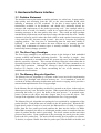
In the Memory Recycle Algorithm, each buffer is treated as an object, in that only one
distinct process can ‘own’ the buffer at a time. When a particular process has finished
processing the buffer, it ‘gives’ the buffer to the next process – in practical terms,
passes a pointer to the object, and then ‘forgets’ that it ever saw the object. This
concept in the algorithm is the part that implements the Zero-Copy paradigm.
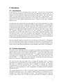
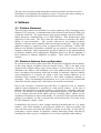
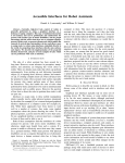
The Memory Recycle Algorithm can perhaps be best explained by explanation of the
packet lifecycle. Each packet starts as a buffer in the free packet pool. When the NIC
signals that a packet is ready to be received, the Ethernet driver is called. It requests a
buffer from the free packet pool and transfers the data into the buffer via DMA.
When DMA completes, the driver is called again and the packet is transferred into the
queue of packets that the stack is processing. The driver returns and the stack then
processes the packet. Upon completion of the processing, the stack gives the packet
back to the free packet pool. The stack will then usually need to produce a response.
To do this, it requests a buffer from the free packet pool, fills the buffer with data, and
9
the response buffer is put on to the queue of packets ready for transmission by the
driver. The driver is then called again, and if the NIC is ready for a packet to be
transmitted, then the packet is transferred via DMA. When DMA completes and the
packet has been transmitted successfully, then the driver gives the buffer back to the
free packet pool.
The algorithm avoids the overheads of memory allocation and de-allocation by
effectively simplifying the memory allocation scheme for packets, which also has the
benefit of reducing memory fragmentation to zero – given the small amount of
memory available for processing packets, and the otherwise high allocation/deallocation rate, this is a highly desirable result. One drawback is that, in the simplest
of implementations at least, the buffers in the free packet pool must be at least large
enough to hold a complete IPv6 packet. This could be overcome by having multiple
free packet pools, with different size buffers in each. Carrying this to the extreme
would however eventually result in the normal memory-allocation behaviour of the
system.
If many small packets are sent, in a system that has only the one packet pool of
maximum size packets, then memory usage is not very efficient, except for one point
– memory allocation can be controlled with respect to time, instead of just with
respect to memory available. Consider the situation where the buffers have been
Stack data
Free Packet Pool
I/O Buffers
NIC
B
Packet 1
D
Packet 1
A
Packet 1
G
Packet 2
E
Packet 2
H
Packet 2
Packet n
F
C
A The driver detects an incoming packet, and gets a pointer to a free buffer
B DMA occurs to fill the buffer with data
C The driver passes the full buffer pointer to the stack for processing
D The stack processes the data and gives the pointer back to the free packet pool
E The stack gets a pointer to a free buffer and fills it with the packet response
F The stack passes the full buffer pointer to the driver for transmission
G DMA occurs to transmit the data in the buffer
H Once transmission is complete, the buffer pointer is given back to the free packet pool
Note: Conceptually each buffer is treated like a physical object, in that only one entity has
possession of it at any one point in time. It is explained with pointers in this diagram for
clarity.
The Memory Recycle Algorithm: Data flow
10
exhausted, and the stack wishes to compose a transmission. Under a normal memoryallocation scheme, the memory allocation would fail – usually desirable; as in a
normal system there is no guarantee that memory will become available. In the
situation of the data processing system detailed above however, memory becoming
available is just a matter of time – time for the hardware to complete its current
transmissions and free some more buffers. Under the Memory Recycle Algorithm,
the memory allocation is blocked if no buffers are available – naturally only for nondriver processes. This means that the data flow can be controlled to where demands
can be met in all places in the system – effectively making more efficient use of
memory by using it where it is needed most. This also makes the data-processing
programs easier to write, as the sensible behaviour for a process in this state would be
to poll the free packet pool until it had buffers available. In the case of the driver, the
driver can drop packets, or delay reception of packets, without substantial effect on
the system, as IPv6 assumes a lossy link-layer. The last effect of controlling memory
usage this way is that the total memory usage of the IPv6 subsystem is fixed, and
hence memory availability can be guaranteed for other processes in the system, given
that IPv6 operation is unlikely to be the primary operation in any particular embedded
system.
One last point to make is that while one free packet pool has been assumed to exist
above, in practice two were used – one for packets being transmitted and one for
being received. This is so that the entirety of the free packet pool cannot be utilised
by incoming packets, deadlocking a system hence unable to make outgoing
transmissions.
3.4. The Memory Recycle Algorithm – Problems and Solutions
There are some practical faults in the implementation of the Memory Recycle
Algorithm detailed above – one of which is the basic assumption that packets are
independent, and that time is the only thing limiting buffer flow around the system.
However, the algorithm can be modified to work around these blocking points without
too much difficulty.
11
Stack buffers
Free Receive Buffers
Driver Receive
Rx Packet 1
Rx Packet 1
Rx Packet 1
Rx Packet 2
Rx Packet 2
Rx Packet 2
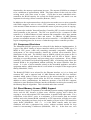
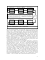
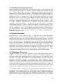
Stage 1: Receive packet 1 comes in, is processed, and a response (Transmit packet 1) is generated
to an unknown address. The response is hence frozen, and an address resolution packet (Transmit
packet 2) is sent in order to get a hardware address to send the response to. Receive packet 1 is
freed. Meanwhile, Receive packet 2 is received – an independent request. It is processed, but
when the stack tries to get a transmit buffer in order to send a response, it is frozen until a transmit
packet becomes free, hence freezing receive packet 2.
Stack buffers
Free Transmit
Tx Packet 1
Tx Packet 1
Tx Packet 2
Tx Packet 2
NIC
Driver Transmit Buffers
Tx Packet 2
The Memory Recycle Algorithm: Four Steps to deadlock (Part 1)
One clear blocking point at the level of code that this project is concerned with is
address resolution. When a packet is addressed to an IPv6 address that the system
cannot yet map to a hardware address, the packet is put on a queue and an address
resolution request is sent. When an address resolution response arrives, this queue is
checked and any outstanding packets that can be sent, are sent. However, if too many
packets requiring address resolution are queued, then the transmit buffers can become
blocked. When the transmission buffers become blocked, the blocking effect
propagates through the system – the stack cannot compose responses because it has no
buffers to compose them into, and it cannot receive any more packets because it is
waiting for transmit buffers in order to complete processing on previous packets. This
results in deadlock if not checked by other mechanisms.
The first phase of this occurrence can be seen in the diagram above. In this case, a
packet (Rx Packet 1) is received by the Ethernet driver, and is then passed along to the
stack, which generates a response. The response is directed towards an IPv6 address
that hasn’t been seen yet – hence there is no way to send the packet, since all Ethernet
packets must have a hardware destination address. The response (Tx Packet 1) is put
in a queue awaiting address resolution, and an address resolution request (Tx Packet
2) is sent out in order to get the hardware address to which Tx Packet 1 must be sent.
Since the stack was able to get a transmit buffer and compose a response, processing
of Rx Packet 1 completes, and Rx Packet 1 is released into the free packet pool. A
second packet (Rx Packet 2) is then received by the driver and passed along to the
stack. Unlike the previous packet, processing on this packet cannot be completed, as
there are no transmit buffers available in which a response can be built. The transmit
buffer allocation procedure locks the IPv6 stack until a transmit buffer becomes
available – in this case when the address resolution request finishes transmitting.
12
Stack buffers
Free Receive Buffers
Driver Receive
Rx Packet 3
Rx Packet 3
Rx Packet 3
Rx Packet 2
Rx Packet 2
Rx Packet 4
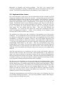
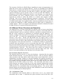
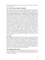
Stage 2: Tx Packet 2 (The Address Resolution Packet) is sent, freeing up a transmit buffer for
Receive Packet 2. The stack generates the response (Transmit Packet 3) to Receive Packet 2, again
to an unknown address. An address resolution packet must be sent, but there are no free transmit
buffers – hence Transmit Packet 3 is frozen for the time being. Receive Packet 2 is however
released. In the meanwhile, reception continues and Receive Packet 3 comes into play – again,
being frozen as there are no free transmit buffers. Receive packet 4 delivers the coup-de-grace.
Stack buffers
NIC
Free Transmit Buffers Driver Transmit Buffers
Tx Packet 1
Tx Packet 1
Tx Packet 3
Tx Packet 3
The Memory Recycle Algorithm: Four Steps to Deadlock (Part 2)
The second phase of this occurrence can be seen in the next diagram. In this diagram,
the address resolution request is sent, freeing up a transmit buffer and hence allowing
processing of Rx Packet 2 to continue. In this case, the response to Rx Packet 2 (Tx
Packet 3) is also to an address whose hardware address is unknown, but there are no
free transmit buffers in which to compose an address resolution request. This is not
too much of a problem – this packet can be sent later, but it means that the second
transmit buffer is put on the queue, awaiting address resolution. This situation would
be resolvable, if the next packet were the packet resolving the address for Tx Packet 1.
That would allow Tx packet 1 to be sent, freeing up its transmit buffer. Instead two
more packets are received – Rx Packet 3 and Rx Packet 4. The processing of Rx
Packet 3 stops at the stack, as there are no free transmit buffers, and hence freezes the
stack. Rx Packet 4 is received by the driver, but is not processed, as the stack is still
completing processing of Rx Packet 3. The resulting situation is that the system is
deadlocked, as it requires an address resolution response in order to free up its
transmit buffers, but the address resolution response cannot be received because the
receive buffers are full.
This may at first glance seem to be symptomatic of a lack of buffer memory –
certainly the situation will be exacerbated by a lack of buffer memory. However,
merely increasing the amount of buffer memory will only make the problem less
likely to occur, as in a theoretical sense, this problem could clearly occur regardless of
the amount of buffer memory unless other steps were taken.
13
There are however solutions to this problem – three of which are detailed below. A
complete solution would likely combine aspects of each solution, as some have the
advantage of simplicity, while others offer better performance in general.
3.4.1. Deadlock detection and buffer flushing
One way to deal with the problem of deadlock in this manner is with co-operation of
the IPv6 stack. In this case, the stack updates a variable when it receives each packet
– as to whether it is an address resolution packet or not. In the case where the
transmit buffers are all engaged, a situation that is easy to detect in the buffer
allocation function, these buffers can be checked to see if they are waiting on address
resolution. If they are, then the transmit buffers can be flushed, freeing them up for
new responses. This method is perfectly valid in IPv6, as it expects to see a lossy
transmission medium, but it is not very efficient due to the amount of CPU time
already spent processing the relevant packets. A similar variant on this is to have a
separate module for address resolution, filtering out non-address-resolution packets in
situations where all the transmit buffers were waiting on address resolution. This
variant would still have to drop packets from the transmission queue however, for
retransmissions of address resolution request packets. This method is one of the
simplest solutions, but probably the least efficient.
3.4.2. Dedicated Privileged buffers
Another way of dealing with the deadlock problem as outlined above is by the
introduction of dedicated buffers for address resolution. Address resolution packets in
IPv6 are only 100 bytes, compared to full-size Ethernet buffers at 1.5 KB, or
minimum MTU size IPv6 buffers at 1.2 KB. This solution would set aside small
sized ‘privileged’ buffers only usable by address resolution code. In the case of
address resolution transmissions, these buffers would recycle quickly and reliably,
since address resolution requests are targeted towards multicast addresses, which are
already known. In the case of address resolution responses however, filtering would
need to be performed. The first filter would be at the Ethernet driver level, which
would drop any packets too large to be an address resolution packet. The second
would be at the stack or address resolver module, which would filter any packets that
were not address resolution responses. This solution is an improvement on the
method above, as it does not waste the processing time that has already been used
producing packets, but instead provides an out-of-band channel in the buffer
management in order to get requests through. It is still relatively simple however.
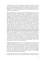
3.4.3. Packet-Assemble-Instructions (PAI) Queues
The Packet-Assembly-Instructions (PAI) queue is a different way of looking at the
problem. It is based on the observation that there are some packets that are static,
very close to static, or are responses in request-response pairs where the response is
very similar to the request. Neighbour discovery packets and ping responses fit into
this category. The normal sending of a Neighbour Discovery Request, for instance,
involves copying most of a static structure into a buffer, modifying the address to
which it is to be sent, and then calculating the ICMPv6 checksum. In the case of a
ping response it is similar - it is the copying of a static packet header coupled with a
copying of the additional request data. Again, the checksum is calculated across the
entire packet.
14
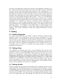
Process Ping
Ping Packet
Ping data
Free
Buffer
Allocate Buffer
Pong Template
Copy Template
Copy data
Pong Packet
Ping data
Send buffer
Normal Ping Processing and Pong Assembly
This is inefficient, both in its use of memory and processing power. The Neighbour
Discovery request could be represented as a pre-built packet, along with an instruction
to modify two fields - the destination address and the ICMPv6 checksum. The
ICMPv6 checksum could be recalculated more quickly by taking the checksum of the
existing packet and combining it with the checksum of the new destination address,
rather than the entire packet. (This is of course assuming that there is no encryption in
place). The entire set of Neighbour discovery requests could hence be represented by
a declaration of the static portions of the packet, along with {new destination, new
checksum} parameter pairs. Ping responses could be represented the same way, using
the same incremental checksum update techniques, with the exception that they would
have to include a pointer to the ping data to be sent. This leads to the idea of the
Packet-Assembly-Instructions queue. The idea of the PAI queue is that instead of
filling a buffer for certain packets, instructions for packet assembly are sent. The
driver could then modify a static buffer containing the appropriate packet format and
immediately transmit the packet to the hardware. This would mean that the
processing could be done more efficiently, as only the necessary data is copied inside
the CPU, and also only one copy of the static data is used at all, and hence the use of
memory is vastly more efficient. The assembly could however only be done at the
driver level, as only the driver can guarantee synchronised access to write to the static
data structures. Stack layering would still be preserved, as the packet formation
would still effectively be done at the correct level of the stack.
15
Process Ping
Ping Packet
Ping Data
Calculate response
parameters
Send PAI
Packet Reception
and DMA
Pre-calculated
Parameters
Pre-assembled
Header
Packet Assembly
and DMA
NIC
Ping Processing and Response using Packet-Assemble-Instructions (PAI) Method
This takes the idea of Zero-copy one step further - instead of avoiding copying the
packet around in the CPU, it avoids even assembling the packet in the CPU, and it
achieves this in an efficient way that requires very little processing.
It allows a very low memory-usage out-of-band channel to be constructed, aiding the
solution of the deadlock problem in the transmit path, but handling of the receive path
would have to follow a similar procedure as outlined under the other solutions.
3.5. Multi-Buffering
The use of DMA allows the parallelisation of data transfer and other tasks, but to fully
exploit this fact software support must be provided as well – parallelising tasks is not
possible without the tasks themselves being parallelisable. In terms of getting
maximum throughput while transferring data to the hardware, this project utilises a
multi-buffering scheme. The effect that this scheme has is that previous data is being
processed while new data is being transferred from the hardware. This requires at
least two buffers per transfer direction – one buffer for the data that is currently being
transmitted, and one ‘working’ buffer where data is being assembled or processed.
This transforms the stack data transfer from what is essentially a ‘stop-and-wait’
scheme to a ‘sliding window’ scheme. The Ethernet driver produced allows the
number of buffers to be easily modified.
3.6. Multicast Reception
Both NICs must be explicitly programmed to receive multicast packets, but can be
programmed to be selective about which multicast packets are to be received. This is
done via the ‘Hash Filter’ in the CS8900A, and the ‘Multicast Address Register’ in
the RTL8019. The mechanism is very similar. When a packet is received, its address
is put through a CRC function to produce a 6 bit code. This six bit code is put
through a demultiplexer to in order to select 1 of 64 bits. If the bit that is selected
matches the corresponding bit in the hash filter register, and that corresponding bit is
set to a one, then the packet is accepted. Due to time constraints, no use was made of
the hash register, but it could be a factor in speeding up processing, as detailed in later
sections. The address so accepted is referred to in the documentation as a ‘hashed
address’, or a ‘hashed multicast address’.
16
3.7. Differences between the CS8900A and the RTL8019AS
The CS8900A is the NIC in the Ethernet Card used on the demonstration board, and
the RTL8019 is the NIC used on the final hardware. The two NICs are quite different
in terms of the programming interfaces that they export, and an understanding of these
interfaces is relevant to understanding the Ethernet driver operation.
The CS8900A exports quite a simple interface – it generates an interrupt, and passes
sequences of event in the Interrupt Status Queue register. The interrupt is edgetriggered, and hence the interrupt logic in the NIC does not have to be reset on return
from the Interrupt Service Routine. This means that there is a period in the Interrupt
Service Routine, after the reading of the Interrupt Status Queue, where new events can
occur, but not generate a response due to the micro-controller ignoring the interrupt
(Unless enabled explicitly, interrupts cannot interrupt Interrupt Service Routines).
The programming interface consists of the queue of events being exposed via the
Interrupt Status Queue, and also a set of control registers which can be written to so as
to execute commands to initiate received buffer transfers or transmissions. It is a
relatively simple interface in terms of transmission and reception, as processes like
buffer management and event queuing are managed on the NIC.
The RTL8019 has, by contrast, a slightly more complex interface, due to more
exposure of the internals to the outside world. The interrupt is level-triggered, which
means that the interrupt logic needs to be reset for each event, as otherwise the
Interrupt Service Routine will be called again by the micro-controller on exit. This
does however provide the advantage that, in the period between the Interrupt Status
Register and the Interrupt Service Routine exiting, the Interrupt Service Routine will
be immediately re-triggered. The memory management of the buffers is reasonably
simple, and is exposed to the micro-controller. Memory management of the NIC
transmit buffer space is left to the micro-controller, and memory management
elements of the NIC receive buffers are manipulable by the micro-controller,
meaning that if jams occur it is immediately clear to the debugger, as contrasted to the
CS8900A where errata and FAQs indicate what operations or sequences of operations
should not be performed. The way that the RTL8019 manages its buffers is by the
control logic for the Receive Buffer Ring – four registers. As the name suggests, the
Receive Buffer Ring is a space in the RTL8019 buffers that is managed by treating it
as a ring of buffers. The four registers that control the Receive Buffer Ring are the
Boundary Pointer, Current Page Pointer, Page Start Pointer, and the Page Stop
Pointer.
The Boundary Pointer is set to the end of the last buffer that the micro-controller has
read, while the Current Page Pointer is set to the beginning of the next free 256-byte
page of buffer memory. If the Current Page Pointer should be incremented such that
it is equal to the Boundary Pointer, then a Ring Buffer Overflow condition is
considered to have occurred, and the NIC will need to be reset.
The Page Start and Page Stop Registers respectively set the beginning and the end of
the Receive Buffer Ring in the buffer RAM. The ability to modify these registers
means that varying proportions of transmit to receive buffer space can be set, which is
an advantage as this ratio can be optimised to the application.
17
The exposure of the Receive Buffer Ring is significant in terms of programming, as it
makes the device easier to program and test. Events are signalled by the Interrupt
Status Queue, as stated before, but the role of the Interrupt Service Routine is then just
to read registers, make decisions on what data to transfer, and trigger transfers, as
opposed to having to process specific events, as is the case with the CS8900A. The
transparency of the buffer management interface is an advantage, as it means that the
micro-controller can form a complete picture of the state of the buffers, vastly
improving its ability to utilise the buffers in a manner that supports software
buffering. This is clear when the following situation is considered: If the stack has
two buffers for reception, totalling 3KB, and the NIC is configured to set aside 13KB
of 16KB of buffer space for reception buffers, then the total amount of space that can
be utilised for buffering is 16KB, assuming that the buffer space is managed in a
sensible manner. This is an example of the maximum utilisation of hardware needed
for high efficiency in systems utilising limited memory.
3.8. Ethernet Driver Structure and Operation
The Ethernet Driver is in the critical path of all packets, and it is hence critical that it
be as efficient as possible. To make the matter more complex, it must fully utilise the
available hardware such as to maximise efficiency, and also be structured with care so
that the correct sequences of operations are performed upon the hardware - for
instance, reading of the Interrupt Service Register on the CS8900A NIC changes the
state of the NIC. It is hence not surprising that the hardware dictates some of the
structure of the driver. Ideally, the ISR should also not impose many (if any)
restrictions on the other processes that produce or consume the data that it processes the interface must be static so that replacement of the hardware driver does not impact
the integration of the stack and the driver. It should also ideally be asynchronous,
such that it does not demand, or rely on, processing from other code. The drivers that
have been developed in this project are strongly event-driven synchronous processes,
which present an asynchronous best-effort (with respect to delay) service to the other
consumer/producer processes. The drivers that were written are identical in the
interfaces that they export to the other processes, and also share some code. They
however vary quite markedly in the Interrupt Service Routine (ISR).
Non Hardware-Specific Functions
The functions that do not have to access the hardware - functions like the transfer
buffer allocation function - are quite simple in structure. They are directly called by
other procedures and either add or delete objects from various linked-lists, with the
manipulation procedure flanked by interrupt disabling and enabling operations in
order to ensure that the operations are atomic. If a receive buffer needs to be freed,
for example, then the procedure merely inserts the free buffer into the free buffer
linked list for the ISR to utilise at its leisure. The send buffer and release receive
buffer functions are unique in that they are the only exported functions that actually
trigger an interrupt. The send buffer function does this only if the NIC is idle, as there
could otherwise be considerable delay in transmitting packets. The receive buffer
function triggers an interrupt only under the same conditions, in order for the Interrupt
Service to quickly process delayed packets.
3.8.1. Initialisation Code
The initialisation code naturally differs in both drivers, but is very similar both
structurally and in intent. It initialises the queue structures used in the driver, the
18
hardware, the interrupts and the DMA. In the case of the Mitsubishi demonstration
board, it sets the DMA controller to trigger off an clock signal internally generated
within the micro-controller, and also initialises a system timer to generate this signal.
In the case of the final hardware, it sets the DMA controller to trigger off the INT1
signal, which is the line to which the hardware trigger is wired. It detects the NIC by
reading the product ID code – naturally if in an embedded system the hardware were
missing, this would be extremely surprising, but this also serves to ascertain that the
hardware is responding correctly and that the system is configured correctly in the
development process.
The initialisations of the NICs follow similar forms: Following a software reset, the
hardware address must be programmed into the unit and the device configured to both
generate and filter interrupts. The physical interface must be selected, as both NICs
offer the ability to work with both twisted-pair and coaxial interfaces, although both
pieces of hardware have only been designed with the external circuitry for twistedpair operation. The multicast hash filter must be initialised, and both transmitter and
receiver parameters configured. In the case of the RTL8019 the ‘endian-ness’ of the
NIC interface can and must be set.
The receiver parameters have been selected such that only correct packets are
received, as although the hardware will accept and pass on packets with checksum
errors and undersized or oversized packets, there is no reason to waste resources
processing these packets. The ability to receive broadcast and multicast packets must
also be enabled explicitly. In the case of the RTL8019, the receive buffer ring must
also be explicitly initialised.
The transmitter parameters have been initialised so as to maximise throughput and
minimise extra processing needed. In the case of the CS8900A, the device is
configured to start transmitting packets after only 381 bytes have been received. This
allows the use of buffer memory for less time, and causes no problem with operation,
as the DMA controller can easily keep up the necessary data rate to supply the chip
with data. The hardware is also configured to generate the CRC checksums at the end
of each packet, as otherwise these would need to be generated in software. In the case
of the RTL8019, there is no option to disable the CRC generator, and the size of the
transmit buffer has already been set in the receive buffer ring initialisation.
3.8.2. The Interrupt Service Routine (ISR)
The core of the driver is the ISR. This is the only part of the driver that interacts
directly with the hardware, apart from the initialisation code. This is done this way so
that all interactions with the hardware can be tightly synchronised and controlled. If,
for example, the send packet and receive packet functions directly wrote to the
hardware, then they would have to be synchronised via wait loops, wasting CPU time,
as otherwise they would interrupt each other's transfers and hence not only would
nothing be accomplished, but the hardware would be left in an unknown state.
The first ISR that was written for this project was the ISR for the Mitsubishi
demonstration board and Ethernet card, which utilised the CS8900A NIC. The ISR
was triggered by either a DMA transfer completing, or by the NIC asserting an
interrupt. The first step upon entering the ISR was to check if the DMA was running
– if it was then the ISR would exit, as it would disturb the DMA transfer if it started
19
reading or writing to the NIC. If the DMA had completed, then it would set the status
of the latest received packet to indicate that it was ready for passing to the stack
before reading the Interrupt Status Queue on the CS8900A. If the result was nonzero,
indicating that the NIC had signalled an event, then the ISR would execute the event
handling code – otherwise it would continue on to the transmit initiation code to
transmit any outstanding packets.
The event handling code would then check the Interrupt Status Queue value to
determine which particular event had occurred. The most important events were the
Transmit Ready, Transmit Complete, Transmit Terminated and Receive Events – the
others events generated by the NIC are primarily informational, or only useful for
debugging. The Transmit Ready Event would indicate that the NIC was ready for the
next transmission to be started. In this case the ISR would initiate the DMA transfer,
which had been previously set up by the transmit initiation code, and return from the
ISR. The Transmit Complete Event would signal that the most recent transmission
had completed successfully without colliding with other packets. In this case the last
transmitted packet would be taken off the ‘transmitted’ queue and transferred to the
free packet pool, leaving a fresh entry on the top of the transmission queue for the
next time the queue was accessed by the transmit initiation code. The Transmit
Terminated Event was initiated when transmission of a packet was terminated due to
excessive collisions. The ISR increments a counter at the moment, but it would
normally retransmit the packet in this case. The last main event is the Receive event,
indicating that the hardware has received a packet. This event indicates whether the
packet received was addressed to a broadcast, unicast or ‘hashed’ address. The ISR
doesn’t pass this address type information up the stack at this stage, but it may be
desirable for it to do so in the future, in order to speed up address recognition further
up the stack. Upon receiving this event, the ISR would check that the ‘Packet OK’ bit
was set before checking for a free receive buffer. If a free receive buffer was
available, the ISR would allocate it and then initiate DMA to transfer the packet into
the waiting buffer. If there were no free receive buffers, then the ISR would issue a
‘skip packet’ command to the NIC in order to avoid overflowing the internal memory
– an event that would require a minimum of a 10 ms reset time to correct. The ISR
would then return. Should the ISR process an event that did not require returning
from the ISR, it would loop back to the start and continue reading the Interrupt Status
Queue until the time at which the Interrupt Status Queue held a value of zero,
signalling that no events were currently outstanding.
If the ISR had not returned by this point, it would check to see if there were any
outstanding transmission requests. If so, it would initiate them, which involved
writing a transmission event to the hardware and then checking a status register to see
if the NIC was ready for data to be transmitted. If the NIC was ready for the data, the
ISR would set up and initiate a DMA transfer. If not, the transmission request would
later result in a Transmit Ready event, which would initiate the transfer of the packet
to the NIC. The packet status would then be marked as ‘started’, and if the DMA
transfer had taken place, the packet would be transferred to the ‘transmitted’ buffer
queue, awaiting confirmation of its transmission. If there were no outstanding
transmission requests, then the ISR would just exit.
Several things to note in this structure are the partitioning of events with respect to the
reading of them, and the necessity of dealing with events first in the ISR, as opposed
20
to last. In the CS8900A, the reading of events changes the Interrupt Status Queue,
and also changes the state of the hardware. For an example, if an Interrupt Status
Queue read occurred during a DMA transfer of a packet to the micro-controller, the
read would be interpreted as an ‘implied skip’ – and the internal buffer in which the
packet resided would be de-allocated, ensuring that the packet data would be
irretrievable. This means that events must be partitioned, in that the event that the
Interrupt Status Queue signals must be completely processed before the next event is
read, even in the case of events that do not require reading the Interrupt Status Queue,
such as the transmission of packets, which can be polled. The approach of combining
DMA read and writes (Transmitting a packet to the NIC at the same time as receiving
a packet from it) was attempted, but the hardware failed to work under these
conditions. This was unfortunate, because the ability to transfer data using two DMA
channels would allow higher use of data bus bandwidth, but it did not come as a
surprise. The necessity of processing NIC signalled events before actuating driver
transmit events was prompted by earlier code revisions that failed to operate correctly
when processing driver transmit events first. The relevance of the former point is that
the hardware affects the structure of the ISR – in this case, the ability to read the
hardware status at any time does not exist. The relevance of the latter point is that
processing the transmit events first would be a little better, as the processing of the
transmit events before the receive events follows the natural data flow of the system.
For an example, consider the situation where the receive buffers are full, and the stack
is waiting on a transmission in order to continue processing packets. If data cannot be
transmitted before the receive events are processed, then incoming packets must be
skipped before the transmit event can take place in order to free up the stack. If the
transmit event can occur first however, then the possibility exists to leave the receive
event unprocessed and hence let the stack do more processing and free up a receive
buffer for incoming packets, letting the ISR process the incoming packet at a later
time, hence avoiding having to drop the packet. This shows what subtle effects the
hardware can have on system dataflow.
The second ISR was for the final hardware produced in this project, utilising the
RTL8019AS. This ISR was also triggered by both hardware interrupt and by DMA
completion. This first step in this ISR was to check a state variable, indicating
whether the ISR was in a state where it was completing DMA, or whether it was
responding to an NIC interrupt. The state variable is necessary because it is not
possible to determine the interrupt source without querying the hardware [CHECK
THIS], and due to the way that both the hardware and the RTL8019 were designed it
is not possible to check the Interrupt Status Register during DMA. This is for two
reasons. The first is that the registers in the RTL8019 are divided into four pages, and
the register that selects which page to expose to the system bus is also the page that
controls the DMA requests, including the DMA abort. The second is due to a minor
error in the hardware that means that the bus width must be switched between eight
and sixteen bits when accessing control registers and performing DMA respectively.
In the case where the ISR has been triggered by DMA completion, the ISR switches
the bus back into eight bit mode, and then checks the top elements of both the transmit
queue and the receive queue to determine whether the event was the completion of
transmit DMA, or receive DMA. In the case of the receive DMA finishing, it sets the
status of the packet to 'done', making it ready to be picked up by the stack. It then
updates the boundary pointer register in the RTL8019 to indicate the point up to
21
which it has read. In the case of the transmit DMA finishing, it goes through a short
wait cycle, checking the Interrupt Status Register until it has determined that the
RTL8019 has internally completed the DMA transfer, before moving the packet from
the transmit queue to the transmitted queue, reading for the transmit command. After
the ISR has completed the appropriate post-DMA processing, it resets the 'DMA
completed' flag in the Interrupt Status Register. The Interrupt Status Register is the
register that signals what event has caused a hardware interrupt - if it is non-zero, then
the RTL8019 interrupt line is asserted. The ISR then re-enables the hardware
interrupt that would normally trigger it, and resets the state variable. The hardware
interrupt that would normally trigger the ISR is disabled during DMA transfers
because the Interrupt Status Register, as noted before, cannot be read during DMA.
The ISR then reads the Interrupt Status Register to check the status of the NIC. The
first bits that it checks are the 'Transmit completed ok' and the 'Transmit failed' bits,
indicating the obvious. In the case of a successful transmission it frees the most
recently transmitted packet by transferring it to the free packet pool, and updates a
static variable that keeps track of the RTL8019 transmit ring buffer usage. In the case
of the transmit failing, it merely changes the state of the packet, indicating that it
needs to be retransmitted. After these processing steps are complete, it resets the bits
that it uses in the Interrupt Service Register - in a similar manner to the DMA. It is
worth noting that each functional section in the ISR only resets the bits that are
responsible for triggering them. This is because the Interrupt Status Register can
change over the execution time of the ISR, and if they cleared all bits, then they
would eliminate critical status information, causing severe ISR malfunction.
The next step of the ISR is to check for any packets that are ready to be transmitted.
If there are, then the size of the packet, in 256 byte pages, is calculated, and hence it is
determined whether there is enough space in the RTL8019 transmit buffers for the
packet. If there isn't, then execution continues after this stage of the ISR. If however
there is space then the NIC hardware interrupt is disabled, the chip is configured to set
up a DMA transfer, the bus is put into sixteen-bit mode, and a DMA transfer is
initiated. The state variable is also set to indicate that a DMA transfer is in progress.
At this point the ISR returns, as it must wait until it is called again by the DMA
transfer completing, as it cannot do anything until the DMA transfer is complete.
The last step of the ISR is to read the current page pointer and the boundary pointer
from the RTL8019. The current page pointer indicates where the NIC has written to
in the Receive Ring Buffer. The boundary pointer indicates where the microcontroller has read to in the Recieve Ring Buffer. The ISR checks to see whether the
two values are equal. If they are, then nothing is available to be received, and the ISR
clears any miscellaneous bits (Unused informational bits) in the Interrupt Status
Register and returns. If however the two values are not equal, then the NIC has
received a packet that must be transferred. It clears the 'Packet Received OK' bit in
the Interrupt Status Register and checks the Free Packet Pool to see whether there is a
free buffer. If there isn't, then the ISR returns. This means that the NIC will buffer
the packet in the meantime, and the ISR will receive it later when there is a free buffer
available. It then disables the NIC hardware interrupt and configures the RTL8019
for a DMA transfer before switching the system bus into eight-bit mode and initiating
the DMA transfer. At this point the ISR returns.
22
There are a couple of differences between this ISR and the previous one. Though the
operations are still partitioned because of hardware usage, the order of the operations
is much more flexible, as the state of the hardware is only changed explicitly, not
implicitly. This means that receive operations can be delayed and packets left in the
hardware buffer for later processing, enabling the order of driver operations to follow
the natural data flow of the system. The second main difference is because the
RTL8019 only changes its internal state by explicit operations, the demands on the
ISR are relaxed, as there is little danger of losing data by out-of-order operations. The
other side to this of course is that some smarter management is needed in the ISR, but
this works to the advantage of the programmer by increasing the flexibility. In this
ISR, for an example, the amount of free transmit buffer space in the NIC could be
read, and then if it was not possible to transmit the oldest packet due to size
constraints, then the transmit packet queue could be checked for an appropriately
sized packet. Due to time constraints, this was not implemented, along with a few
other elements that would improve the robustness and efficiency of the driver, such as
checking for Receive Buffer Ring overflows.
3.9. Implementation Issues
There were a number of issues experienced in the programming of the hardware/
software interface that made it more difficult. Some of these were from the compiler,
some from the documentation available, and some were a result of hardware issues.
The issues with the compiler were in code generation. In certain cases, the compiler
would fail to perform shift operations correctly, instead setting the variable to zero.
This problem had to be resolved and debugged down at the assembly-language level,
and the debugger (Running on the PC and communicating with the board via serial
port) provided with the development kit proved an invaluable tool in resolving this
problem. However, much care had to be taken in writing further code, as even with
care, this error was experienced several times. The second code generation problem
related to near and far pointer parameters to functions. The micro-controller, being a
16-bit device with a larger than 16-bit address space has the concept of near and far
pointers – the near pointer being 16 bits, and the far pointer being 32 bits. In the case
of pointers being passed as parameters the pointers were not automatically converted
– for instance, two bytes of pointer data would be pushed onto the stack, and four
bytes taken off as a parameter. This problem was bypassed by using explicit casts on
some parameters to functions, although it came up a number of times, as much care
had to be taken to avoid the situation. These issues had a strong effect on the
development of the code, as a compiler is usually a trusted part of the system, and
hence compiler error is one of the last possibilities to be considered and examined.
The RTL8019 documentation was the second major issue – the datasheet that Realtek
produced for the RTL8019 is insufficient to program the device, and it is difficult to
program and understand a device based on public driver code written for other
operating systems and architectures. Fortunately, upon contacting Realtek, they were
able to provide me with datasheets that were sufficient to program the device – in fact
devices for a National Semiconductor chip that the RTL8019 was an upgraded clone
of. The material that they gave me also had example drivers for some embedded
systems, as well as popular PC operating systems, but these were only of limited use,
since the embedded drivers were primarily using polled mode, instead of interruptdriven I/O.
23
The last issue experienced with the hardware/software interface was due to the 8/16
bit hardware error detailed in the hardware section. This took some time to debug, as
the problem eventually had to be diagnosed with an oscilloscope.
4. Software
4.1. Problem Statement
The stack that needed to be modified was a stack written by Chris Gascoigne for the
Infineon C167 processor. It communicated via the Point-to-Point Protocol (PPP) over
a 9600 bps serial line. The requirements of this project dictated a stack for an M16Cfamily processor, communicating via 10 Mbit Ethernet. This dictated three main
objectives for the stack. The first is that the stack had to be ported to the M16C
family of micro-controllers. The second, achieved by the hardware-software
interface, is that the micro-controller had to be interfaced to the NIC. The last is that
additional support is required in order to support IPv6 over Ethernet. Unlike PPP,
Ethernet has multiple destinations reachable on one interface, and hence requires
hardware addressing. Other requirements specific to Ethernet are the implementation
of Stateless Address Auto-configuration, Neighbour Discovery and the mapping of
IPv6 addresses to Ethernet Addresses in general. These will be detailed in later
sections.
4.2. Stateless Address Auto-configuration
In a protocol such as IPv4, nodes must either be statically configured with an address,
or they must request an address from an external source. This is due both to the
design and the limited address space of the protocol. In IPv6 however, 128 bits are
allocated to the address, and in addition, one of the addresses that an interface may
have is an address scoped purely to the link to which it is attached. Stateless Address
Auto-configuration is a process by which a node may allocate addresses to its
interfaces itself, instead of being forced to have them configured statically or
externally. This is an advantage in deployment, as it is part of a set of features that
make IPv6 literally “plug’n’play” with respect to a network environment.
Due to the vast array of network types that IPv6 is expected to run on, Stateless
Address Auto-configuration is specified in a link-specific manner. In the case of
Ethernet, the host portion of the IPv6 address is formed from a identifier called the
EUI-64. The EUI-64 is an identifier that is guaranteed unique to each Ethernet node,
as it is formed from the 48-bit Media Access Controller (MAC) address by the
expedient of inserting two bytes in the middle. To use the EUI-64 to generate the host
portion of an address, one bit is inverted (the universal/local bit) is inverted in the
EUI-64 (Thomson., Narten., 1998).
Unfortunately, the process is more complex than the generation and use of a ‘magic
number’, since other methods of generating an address on a link are possible, and
hence the host must check that the address is unique on the link. It does this by
performing a process known as Duplicate Address Detection (DAD), and then by
searching for routers to give it a link prefix so as to form a globally unique address.
24
4.3. Duplicate Address Detection
Duplicate Address Detection (DAD) is performed by forming a tentative address from
the EUI and the link-local prefix, which is a special network prefix meaning ‘on this
link’. The host then sends a number of Neighbour Solicitations, querying whether
another host is already using the address. The Neighbour Solicitation message is a
general message that is used for querying the mapping of IPv6 addresses to Ethernet
Addresses on a link. If another host is either using the address already, or is testing
the address with a view to using it, then Duplicate Address Detection fails, and the
interface must be configured manually. This situation can be detected by either
receiving a Neighbour Solicitation message querying the tentative address, or by
receiving a Neighbour Advertisement – a message stating the Ethernet address
mapping to the IPv6 address. In order to be able to receive a Neighbour
Advertisement message, a host is required to include its Ethernet address in the
Neighbour Solicitation, so that other hosts have a hardware address mapping that they
can use to address a reply. The Neighbour Solicitation message is addressed to a
special IPv6 address – the Solicited Node Multicast address, formed by a SolicitedNode Multicast prefix and the lower 24 bits of the address required (Narten.,
Nordmark., Simpson., 1998).
4.4. Router Discovery
Router discovery is fairly simple in IPv6 – a host sends out a Router Solicitation
message, addressed to the all-routers multicast address, and if there are any routers
attached to the link, they will reply with a Router Advertisement message, containing
the prefixes for the link, as well as other parameters that the host should or may use –
such as the Time-To-Live for outgoing packets, the link MTU, and optionally the
router’s link-layer address. The host then combines the advertised network prefixes
with its host identifier to get a unicast addresses scoped globally, or to the site. The
information in the Router Advertisement is however time-limited, and includes an
expiry date, at which point the host may no longer use the prefix (Narten et al., 1998).
This is intended to allow site easy renumbering. Unfortunately, due to time
constraints, this timing out of router information has not yet been implemented.
4.5. Neighbour Discovery
Neighbour Discovery is the IPv6 equivalent to the Address Resolution Protocol
(ARP) - it is the protocol that maps IPv6 addresses to hardware addresses on
multicast-capable links. Neighbour Discovery also keeps track of reachability in both
directions. To map an IPv6 address to an Ethernet address, the host sends out a
Neighbour Solicitation message, as detailed above under Duplicate Address
Detection. If it gets a Neighbour Advertisement back, then it knows the Ethernet
address, and also that the host is bidirectionally reachable at that point in time, and so
it caches the address for a time defined by the mandated ReachableTime variable. If
it fails to receive a Neighbour Advertisement in a certain amount of time, then it will
retransmit the Neighbour Solicitation a certain amount of times (Narten et al., 1998).
The behaviour above is sufficient to get enough address information to be able to
transmit packets to the specified IPv6 address, but it does not address questions of
reachability. The Neighbour Discovery specification specifies a number of states that
addresses may be in at certain points, and appropriate actions to take. Due to time
restrictions, the complete Neighbour Discovery specification has not been completed
25
in this project, although there is enough implemented to allow the project to function,
if non-compliantly.
4.6. IPv6 to Ethernet Address Mapping
IPv6 has a number of address types – unicast, multicast, and anycast, to name a few.
Some of these addresses have corresponding addresses in Ethernet – the ‘all link local
nodes’ multicast address directly maps onto the Ethernet broadcast mechanism. The
unicast addresses must clearly map onto corresponding unique Ethernet addresses.
The other multicast addresses also have equivalents, and since multiple multicast
addresses are provided on Ethernet, a mechanism has been specified to map IPv6
multicast addresses to Ethernet addresses - albeit imperfectly, but sufficiently, such
that nodes will not have to process excessive quantities of broadcast messages in the
case of extensive multicast usage. This mapping is an effective use of the medium,
but increases processing time, as the type of address and the mapping must be
determined for each and every outgoing packet – there is a similar occurrence at the
reception end of the stack, where the stack has to check the address against the
multiple addresses that it either owns or listens to. A way to optimise this is to pass
up and down the stack information about which class an incoming or outgoing address
falls into. This optimisation has not been implemented (time constraints), but the
multicast mapping has been implemented for all multicast addresses which the stack
is expected to send or receive at this point – mostly addresses used by processes such
as Neighbour Discovery. An additional, but not overly significant, overhead is that in
order to receive packets addressed to multicast addresses, the driver should be
instructed to program the NIC to receive packets from these addresses (The
alternative is to receive all multicast packets, lowering efficiency). This involves a
checksum calculation duplicating the checksum hardware in the NIC. This would
only be an issue if large amounts of multicast groups were joined and left constantly –
using a lot of CPU time and requiring that the addresses be kept track of. At the
current time, the driver does not have this functionality, and instead accepts all
multicast addresses.
4.7. IPSec
IPSec is the security and encryption layer for IPv6, and it is a requirement for all IPv6
nodes to implement (Loughney., 2003). The minimum requirements for IPSec are
that the ESP and AH protocols are implemented. IPSec was not implemented in the
stack due to time constraints. It will however have a significant effect on the
feasibility of IPv6 on embedded micro-controllers because it involves a dataprocessing step over most of the packet, which will slow the stack down considerably.
This may be a function better implemented in specialised hardware positioned
between the micro-controller and the NIC, as the encryption methods supported in
IPv6 have been selected to be able to be performed efficiently in hardware. In
addition to this requirement, automatic key generation may be too higher a load for
the micro-controller to handle while dealing with other tasks.
4.8. Implementation Issues
The implementation issues experienced during the work on the stack were similar to
the issues experienced in the software/hardware interface programming. The
compiler’s code generation was a factor in the stack programming, as well as in the
hardware/software interface.
26
In terms of selecting code to modify, the code that I was originally to modify was in
fact a different stack that had already been ported to the M16C, but the commenting
was poor, and the code a little untidy, with sections of code commented out – so I
decided to use the original stack that it had been based on. It was noticed that some of
the standard C routines were a little slow, and so for time-critical sections of the code,
functions such as memcpy() have been replaced with macros to do fixed-length copy
operations, which produced substantial improvements. These sort of modifications
have not been implemented throughout the code however, and the code as it stands
could benefit from many optimisations, as the focus of the project in terms of the time
constraints was to prioritise the objective of getting at least a minimum set of
functionality. As a result, complete compliance was not achieved in all modules, and
some optimisation work would benefit the stack greatly. One example of this is in the
addressing module – the Neighbour Cache should really be a direct-mapped cache,
but was implemented very quickly as a fixed array structure with first-in-first-served
mapping. This simple modification would show significant differences in stack
performance.
5. Testing
5.1. Problem Statement
For an IPv6 implementation to be useful, it must be known to follow the IPv6
standards so that it can communicate with other devices, including devices from
different vendors. The way that this is done is to do conformance testing – running a
test suite that can report whether the stack satisfies the requirements. The TAHI test
tools are tools that were designed for such a purpose, and satisfy the requirements for
IPv6 testing. However, during the development process conformance tools are not
necessarily useful, as often very localised tests testing specific or incomplete
functionality are required.
5.2. Testing Setup
The WANDNet test network was used to test the hardware and software in the
development stages. The FreeBSD operating system was installed on two spare PCs,
and the PCs were connected to WANDNet, along with the device under test. One of
the PCs was configured as an IPv6 router, in order to test stateless address autoconfiguration, and the other was configured as an IPv6 host in order to be able to test
on-link (directly connected) and off-link (indirectly connected via a router) data
transmissions. FreeBSD was selected as the operating system to run on the PCs
because the TAHI test tools have been developed to run on *BSD variants, and also
because *BSD contains an IPv6 reference implementation, so the machines that the
project was tested against were known to be compliant.
5.3. Testing Results
Extensive testing was not possible to perform due to time constraints. However, basic
testing through the development process showed that the stack functioned. In terms
of throughput as tested by a flood ping test, the implementation on the final hardware
was able to handle ping packets at a steady rate of 50000 per minute, and that 100000
per minute was possible. In the latter test the stack stopped functioning after a short
time at the higher data rate, and although the matter has not been thoroughly
27
debugged, it is thought that the fault may be a missed DMA interrupt. The figure of
50000 packets per minute is exhibited by the stable implementation, which was
capable of sustaining operation indefinitely. The tests performed much earlier on the
development board showed a sustained packet rate of 36000 packets per minute,
although that stack stopped functioning after a number of minutes at that data rate.
These figures cannot however be compared, as the tests on the development board
used some timing configurations that may have been too conservative with respect to
what the CS8900A is capable of. The reason for the stack stopping functionality had
not been fully debugged on the CS8900A due to time constraints, but the problem is
thought to be linked to an incorrect skipping of packets causing internal memory
management problems inside the CS8900A. The correct manner of processing the
packet skip operations had been implemented as per the documentation, but the
symptoms are the same as if it had not.
Apart from the throughput testing, only function testing has been performed. The
stack correctly auto-configures itself and correctly detects routers and configures link
prefixes. It correctly performs both Neighbour Discovery and Duplicate Address
Detection, and is capable of responding to and addressing hosts both on and off link.
One issue struck with the testing was that the initial routing daemon failed to respond
to Router Solicitations. This was resolved by replacing the routing daemon, after an
attempt at debugging that showed that packets were not being passed correctly to the
daemon. This may have been a configuration error, but the quicker and easier
solution was simply to replace the daemon.
The stack complies with the following node requirements:
It follows the appropriate layer 2 document (IPv6 over Ethernet) (Crawford., 1998)
It processes unrecognised options in hop-by-hop or destination options
It processes extensions as described in RFC 2460
It limits the layer 4 payload size because it doesn’t allow outgoing fragments
It accepts packets addressed to it, but not router packets
Implements Neighbour Discovery [Mostly]
It supports router discovery
It supports prefix discovery
It responds to Neighbour Solicitations.
It implements DAD
It supports sending router solicitations
It receives and processes Router Advertisements
It can send and receive Neighbour Solicitation and Advertisement messages
It supports ICMPv6 (Conta., Deering., 1998)
It supports IPv6 Stateless Address Auto-configuration (Thomson., Narten., 1998)
It uses native addressing instead of transition-based addressing (RFC3484)
6. Conclusion
The following objectives have been met in this project:
o An embedded system has been designed, representing a ‘typical’ embedded
system that maximised the usage of the hardware resources available to it.
o The aforementioned system has been constructed, debugged, fully tested and
works successfully.
28
o A stack for a different processor has been ported to the M16C platform for use
on both the demonstration board and the final hardware produced. This stack
communicated via PPP over serial, and hence the hardware layer driver was
removed.
o An Ethernet driver has been written for each system used in the project
o The Ethernet driver for the CS8900A was moderately successful
o The Ethernet driver for the RTL8019 operates successfully
o Ethernet-specific functionality has been written into the stack, including
Neighbour Discovery, Address Auto-configuration, Duplicate Address
Detection and mapping between Ethernet and IPv6 multicast addresses
o Limited testing has been performed on the stack to ensure that it can configure
itself correctly and communicate with other devices, both on-link and off-link.
o A data flow system has been implemented so as to make efficient use of
memory and time.
Although there is more work to be done in order to make the software produced in
this project fully compliant, this project shows that it is at least feasible to implement
IPv6 on an embedded device. The system produced is capable of up to 100000
packets/minute, corresponding to a data rate of approximately 4 Mb/s each way, with
room for improvement. This is a utilisation of approximately 40% of the link rate,
and a respectable figure for a low powered device. The only barrier to feasibility of
IPv6 in embedded devices that remains is the question of IPSec, which this project
does not address.
7. References
Conta, A., & Deering, S. (1998). Internet Control Message Protocol (ICMPv6) for the
Internet Protocol Version 6 (IPv6), RFC 2463. The Internet Society. Retrieved
5th April, 2003, from http://www.faqs.org/rfcs/rfc2463.html.
Crawford, M. (1998). Transmission of IPv6 Packets over Ethernet Networks RFC
2464. The Internet Society. Retrieved 2nd April, 2003, from
http://www.faqs.org/rfcs/rfc2464.html.
Deering, S., & Hinden, R. (1998). Internet Protocol, Version 6 (IPv6) Specification,
RFC 2460. The Internet Society. Retrieved 18th July, 2003, from
http://www.faqs.org/rfcs/rfc2460.html.
Loughney, J. (2003). IPv6 Node Requirements. The Internet Society. Retrieved 23rd
June from http://www.ietf.org/internet-drafts/draft-ietf-ipv6-node-requirements-06.txt
Mitsubishi Electric Corp. (2001, A). M16C/80 Group Data Sheet Rev. E3. Japan:
Mitsubishi Electric Corp., Kitaitami Works.
Mitsubishi Electric Corp. (2001, C). User’s Manual M16C/80 Group Rev. B. Japan:
Mitsubishi Electric Corp., Kitaitami Works.
Narten, T., Nordmark, E., & Simpson, W. (1998). Neighbour Discovery for IP
Version 6 (IPv6), RFC 2461. The Internet Society. Retrieved 5th April, 2003,
from http://www.faqs.org/rfcs/rfc2461.html.
29
Okabe, N., Sakane, S., Inoue, A., Ishiyama, M., & H. Esaki.(2002) Host
Requirements for IPv6 for Low Cost Network Appliances. Internet Engineering
Task Force (IETF). Retrieved 23rd June, 2003, from
http://www.taca.jp/internet-draft/draft-okabe-ipv6-lcna-minreq-02.txt.
Realtek Semiconductor Co.,Ltd. (2001). RTL8019AS Realtek Full-Duplex Ethernet
Controller with Plug and Play Function (RealPNP). Taiwan:Realtek
Semiconductor Co. Ltd.
Thomson, S., & Narten, T. (1998). IPv6 Stateless Address Autoconfiguration, RFC
2462. The Internet Society. Retrieved 11th April, 2003, from
http://www.faqs.org/rfcs/rfc2462.html.
8. Bibliography
Dunkel, A. (2002). Minimal TCP/IP implementation with proxy support, Thesis
Report, Sweden:Swedish Institute of Computer Science (SICS).
Dunkel, A. (2002). Full TCP/IP in 8 bits. Sweden:Swedish Institute of Computer
Science (SICS). Retreieved 20th March,2003, from
http://www.sics.se/~adam/full-tcpip-in-8-bits.ps
Erikstan, U. (2002). A Small Mobile IPv6 Client, Thesis Report. Australia: The Centre
for Telecommunications and Information Engineering, Monash University.
Gascoigne, C. (2002). IPv6 for Embedded Devices, Thesis report, Australia:
Department of Electrical Engineering, Monash University.
Hagen, Silvia. (2002). IPv6 Essentials. O’Reilly & Associates Inc, Sebastopol,
California.
Hinden, R., & Deering, S. (1998). IP Version 6 Addressing Architecture, RFC 2373.
The Internet Society. Retrieved 18th July, 2003, from
http://www.faqs.org/rfcs/rfc2373.html.
Mitsubishi Electric Corp. (2001, B). Programming Language <C Language>
M16C/80 Series Rev. A2. Japan:Mitsubishi Electric Corp., Semiconductor
Marketing Division.
Mitsubishi Electric Corp. (2000). M16C Software Manual Rev. D1. Japan:
Mitsubishi Electric Corp., Kitaitami Works.
Mitsubishi Electric Corp. (1999). M16C/80 Series Programming Manual <Assembler
Language>. Japan:Mitsubishi Electric Corp., Kitaitami Works.
National Semiconductor Corp. (1995). DP83901A SNIC Serial Network Interface
Controller. Arlington, Texas:National Semiconductor Corp.
National Semiconductor Corp. (1993). Writing Drivers for the DP8390 NIC Family of
Ethernet Controllers. Arlington, Texas:National Semiconductor Corp.
30
31