1
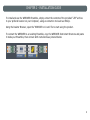
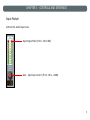
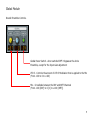
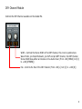
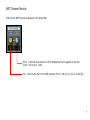
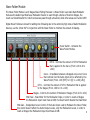
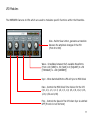
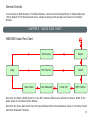
WRECKER - Wave Folder
User Manual • Version 1.0 • August 2015
INTRODUCTION
Thank you, and congratulations on your choice of the WRECKER - Wave Folder.
The WRECKER is a Multi-function Effects Processor Ensemble for use with Native Instruments’ Reaktor.
With focus on Wave Folding Effects the WRECKER also includes a Pulse Modulator, a State Variable Filter,
a Pan Modulator and an Oscilloscope.
You must accept the license agreement to use this product.
Please see www.amazingmachines.com.br/software_eula.html for details.
Reaktor is a trademark of Native Instruments GmbH, all other trademarks and copyrights are property
of their respective owners.
TABLE OF CONTENTS
Chapter
Chapter
Chapter
Chapter
Chapter
1
2
3
4
5
-
System Requirements ...............................1
Installation Guide .....................................2
Controls and Interface ..............................3
Audio Flow Chart ....................................13
MIDI Implementation ..............................14
CHAPTER 1 - SYSTEM REQUIREMENTS
Windows
Windows 7 (Latest Service Pack, 32/64 Bit) or Newer
Intel Core Duo or AMD Athlon 64 X2, 2 GB RAM (4 GB recommended)
Mac
Mac OS X 10.7 (Latest Update) or Newer
Intel Core 2 Duo, 2 GB RAM (4 GB recommended)
General System Requirements
Native Instruments’ Reaktor 5.8 or Newer.
1
CHAPTER 2 - INSTALLATION GUIDE
To install and use the WRECKER Ensemble, simply extract the contents of the provided “.ZIP” archive
to your prefered location on your Computer, using an extraction tool such as WinZip.
Using the Reaktor Browser, open the “WRECKER v1.0.ens” file to start using the product.
To connect the WRECKER to an existing Ensemble, copy the WRECKER Instrument Structure and paste
it inside your Ensemble, then connect both instruments as pictured below:
2
CHAPTER 3 - CONTROLS AND INTERFACE
Input Module
Controls the Audio Input Level.
Input Signal Meter (From -36 to 0dB)
Gain - Input Gain Control (From -18 to +18dB)
3
2-Pole SVF Module
The 2-Pole SVF is a 12dB/Octave State Variable Filter Module that is patched post the Wave Folder
and post the Pulse Modulator Modules.
Power Switch - Activates the 2-Pole SVF Module
Mode - Crossfades between the 3 available Filter Modes
(From -100 [HPF] to 0 [BPF] to +100 [LPF])
Res - Controls the Filter Resonance (From 0 to 127)
LFO 2 - Controls the amount of LFO 2 Modulation that is
applied to the Filter Frequency (From -100 to 0 to +100)
Freq - Controls the Filter Center Frequency (From 0 to 127)
4
Global Module
Overall Ensemble Controls.
Global Power Switch - when switched OFF it bypasses the whole
Ensemble, except for the Input Gain adjustment
LFO 3 - Controls the amount of LFO 3 Modulation that is applied to the Mix
(From -100 to 0 to +100)
Mix - Crossfades between the DRY and WET Channels
(From -100 [DRY] to 0 [X] to +100 [WET])
5
DRY Channel Module
Controls the DRY Channel available on the Global Mix.
Width - Controls the Stereo Width of the DRY Channel, this circuit is patched pre
Wave Folder, pre Pulse Modulator, pre SVF and pre WET Channel, the DRY Channel
Stereo Width does affect all modules in the Audio Chain (From -100 [MONO] to 0 [X]
to +100 [STEREO])
Pan - Controls the Pan of the DRY Channel (From -100 [L] to 0 [C] to +100 [R])
6
WET Channel Module
Controls the WET Channel available on the Global Mix.
LFO 4 - Controls the amount of LFO 4 Modulation that is applied to the Pan
(From -100 to 0 to +100)
Pan - Controls the Pan of the WET Channel (From -100 [L] to 0 [C] to +100 [R])
7
Output Module
Controls the Audio Output Level.
Output Signal Meter (From -36 to 0dB)
Gain - Output Gain Control (From -18 to +18dB)
8
Wave Folder Module
The Wave Folder Module is a 16 Stages Wave Folding Processor. A Wave Folder is an Audio Rate Modulator
that uses the Audio Input Itself as a Modulation Source to scan through a Series of Invertion Stages, the
result is a Sliced Waveform in which some areas pass through untouched, while other areas are inverted 180º.
Digital Wave Folders are known for adding lots of Aliasing due to the extremely high rates of Audio Modulation
Sources, use the 2-Pole SVF in conjunction with the Wave Folder to minimize the amount of Aliasing.
Power Switch - Activates the
Wave Folder Module
LFO 2 - Controls the amount of LFO 2 Modulation
that is applied to the Curve (From -100 to 0 to
+100)
Curve - Crossfades between a Stepped and a Liner Curve
that controls how the Audio Input will be affected by the
Wave Folder (From -100 [STP] to 0 [X] to +100 [LIN])
LFO 1 - Controls the amount of LFO 1 Modulation that is applied
to the Stages (From -100 to 0 to +100)
Stages - Controls the number of Modulation Stages (From 2.0 to 16.0)
Mod Peak - Peak Meter for the Modulation Input, in order to reach all Stages
the Modulation Input must Peak at 0dB, the Reset Switch Resets the Peak Meter
Mod Gain - Independent Level Control of the Audio Input used to Modulate the Wave Folder,
this control doesn’t affect the Audio Output Levels, only the Modulation Levels, in order to
reach all Stages the Modulation Input must Peak at 0dB
9
Pulse Modulator Module
The Pulse Modulator Module is a 16 Stages Pulse Modulation Processor. A Pulse Modulator is an Audio Rate
Modulator that uses the Audio Input Itself as a Modulation Source to scan through a Series of Amplitude
Stages, the result is a Sliced Waveform in which some areas pass through untouched, while other areas have
their Amplitude set to 0. Digital Pulse Modulators are known for adding lots of Aliasing due to the extremely
high rates of Audio Modulation Sources, use the 2-Pole SVF in conjunction with the Pulse Modulator to
minimize the amount of Aliasing.
Power Switch - Activates the
Pulse Modulator Module
LFO 4 - Controls the amount of LFO 4 Modulation
that is applied to the Curve (From -100 to 0 to
+100)
Curve - Crossfades between a Stepped and a Liner Curve
that controls how the Audio Input will be affected by the
Pulse Modulator (From -100 [STP] to 0 [X] to +100 [LIN])
LFO 3 - Controls the amount of LFO 3 Modulation that is applied
to the Stages (From -100 to 0 to +100)
Stages - Controls the number of Modulation Stages (From 2.0 to 16.0)
Mod Peak - Peak Meter for the Modulation Input, in order to reach all Stages
the Modulation Input must Peak at 0dB, the Reset Switch Resets the Peak Meter
Mod Gain - Independent Level Control of the Audio Input used to Modulate the Pulse Modulator,
this control doesn’t affect the Audio Output Levels, only the Modulation Levels, in order to reach
all Stages the Modulation Input must Peak at 0dB
10
LFO Modules
The WRECKER features 4 LFOs which are used to modulate specific functions within the Ensemble.
Slew - Builtin Slew Limiter, generates a transition
between the amplitude changes of the LFO
(From 0 to 999)
Wave - Crossfades between the 5 available Waveforms
(From -100 [SINE] to -50 [SAW] to 0 [SQUARE] to +50
[TRIANGLE] to +100 [RANDOM])
Sync - When Switched ON the LFO will Sync to MIDI Clock
Rate - Controls the MIDI Clock Time Division for the LFO
(4/1, 2/1, 1/1, 1/1.5, 1/2, 1/3, 1/4, 1/6, 1/8, 1/12, 1/16,
1/24, 1/32 and 1/48)
Freq - Controls the Speed of the LFO when Sync is switched
OFF (From 0.01 to 9.99 Hertz)
11
Oscilloscope Module
Source for valuable Visual Representation of the Audio Chain. Note that the Oscilloscope controls
do not affect the Audio Chain in any ways.
Trigger - Selects between the 2 available Trigger Sources
(Light OFF [Audio] and Light ON [Display Clock])
Freeze - Freezes the Waveform Display at it’s Current State
Delay - Controls the amount of Delay between the Audio Input
and the Waveform Display (From 00.0 to 99.9 Milliseconds)
Waveform Display
Y - Controls the Amplitude of the Displayed Waveform
(From -100 to 0 to +100)
X - Controls the Time Span of the Waveform Display
(From 01.0 to 99.9 Milliseconds)
Display - Selects between the 6 available Display Modes
(L I/O, L OUT, R I/O, R OUT, LR IN and LR OUT)
12
General Controls
To set a Knob or Switch back to it’s Default Position, control+click the desired Knob or Switch and select
“Set to Default” from the drop down menu. Double-clicking a Knob will also set it back to it’s Default
Position.
CHAPTER 4 - AUDIO FLOW CHART
WRECKER Audio Flow Chart
Input
Wave Folder
Oscilloscope
Output
DRY Channel
Global
Pulse Modulator
2-Pole SVF
WET Channel
Note that the Stereo Width Control on the DRY Channel Module also affects the Stereo Width of the
Audio Input on the Wave Folder Module.
Note that the Input Gain Control at the Input Module affects the Modulation Input on the Wave Folder
and Pulse Modulator Modules.
13
CHAPTER 5 - MIDI IMPLEMENTATION
WRECKER MIDI Continuous Controller Implementation
0 (Program Change) - Snapshot Recall
3 (Undefined) - Input Gain
9 (Undefined) - 2-Pole SVF Freq
14 (Undefined) - 2-Pole SVF LFO 2
15 (Undefined) - 2-Pole SVF Res
16 (General Purpose # 1) - 2-Pole SVF Mode
17 (General Purpose # 2) - 2-Pole SVF Power
18 (General Purpose # 3) - Global Mix
19 (General Purpose # 4) - Global LFO 3
20 (Undefined) - Global Power
21 (Undefined) - Dry Channel Pan
22 (Undefined) - Dry Channel Width
23 (Undefined) - Wet Channel Pan
24 (Undefined) - Wet Channel LFO 4
25 (Undefined) - Output Gain
26 (Undefined) - Wave Folder Mod Gain
27 (Undefined) - Wave Folder Mod Peak Reset
28 (Undefined) - Wave Folder Stages
29 (Undefined) - Wave Folder LFO 1
30 (Undefined) - Wave Folder Curve
31 (Undefined) - Wave Folder LFO 2
70 (Sound Controller # 1) - Wave Folder Power
71 (Sound Controller # 2) - Pulse Modulator Mod Gain
72 (Sound Controller # 3) - Pulse Modulator Mod Peak Reset
73 (Sound Controller # 4) - Pulse Modulator Stages
74 (Sound Controller # 5) - Pulse Modulator LFO 3
75 (Sound Controller # 6) - Pulse Modulator Curve
76 (Sound Controller # 7) - Pulse Modulator LFO 4
77 (Sound Controller # 8) - Pulse Modulator Power
78 (Sound Controller # 9) - LFO 1 Freq
79 (Sound Controller # 10) - LFO 1 Rate
85 (Undefined) - LFO 1 Sync
86 (Undefined) - LFO 1 Wave
87 (Undefined) - LFO 1 Slew
88 (Undefined) - LFO 2 Freq
89 (Undefined) - LFO 2 Rate
90 (Undefined) - LFO 2 Sync
102 (Undefined) - LFO 2 Wave
103 (Undefined) - LFO 2 Slew
104 (Undefined) - Oscilloscope Trigger
105 (Undefined) - Oscilloscope Freeze
106 (Undefined) - Oscilloscope Delay
107 (Undefined) - Oscilloscope Display
108 (Undefined) - Oscilloscope X
109 (Undefined) - Oscilloscope Y
110 (Undefined) - LFO 3 Freq
111 (Undefined) - LFO 3 Rate
112 (Undefined) - LFO 3 Sync
113 (Undefined) - LFO 3 Wave
114 (Undefined) - LFO 3 Slew
115 (Undefined) - LFO 4 Freq
116 (Undefined) - LFO 4 Rate
117 (Undefined) - LFO 4 Sync
118 (Undefined) - LFO 4 Wave
119 (Undefined) - LFO 4 Slew
To set a Knob or Switch to respond to a specific MIDI Continuous Controller, control+click the desired
Knob or Switch and select “MIDI & OSC Learn” from the drop down menu, then move the desired MIDI
Controller to assign.
14


![Deep Time User Manual ver.1.3 [ENG]](http://vs1.manualzilla.com/store/data/005775250_1-8eb61345983a4e3ef84e4b82ef32f1cf-150x150.png)