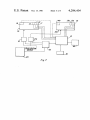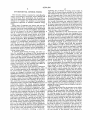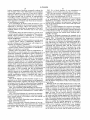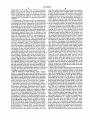
1
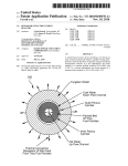
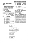
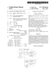
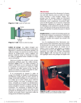
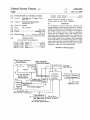
United gtates Patent [19]
[11]
4,294,404
Gajjar
[45]
Oct. 13, 1981
[54]
ENVIRONMENTAL CONTROL SYSTEM
_
[75] Inventor:
n
_
4,084,744 I 4/1978
Wilson, Jr. .......................... .. 236/49
4,114,807
Naseck .............................. .. 236/1 E
9/1978
Jagdishchandra T. GaJJar, Clifton
Park, N.Y.
[73] Assignee: Integrated Energy Systems’
Schenectady, N.Y.
[21] Appl. No.4 877,682
Primary Examiner—William E. Wayner
Attorney, Agent, or Firm—Paul I. Edelson
[57]
ABSTRACT
An environmental control system for improving the
[22]
Filed,
energy ef?ciency of structures is disclosed. A structure
[52]
'
’
Int. (:1.3 .............................................. ..
US. Cl. ...................................... .. 236/49; 236/94;
_
“55/11 A
Feb 14 1978
[58] new of seagcslg
3162/6723?’ 34 (311
/
[56]
having a heating and/or cooling plant, of any conven
tional type, is improved
providing, in each subdivi
Sion of the Structure, such as a room’ a temperature
sensor, and an occupancy sensor. The outputs of the
’
'l
’
/
’
temperature and occupancy sensors are received by a
/9 C
control subsystem whose output is a composite function
References Cited
U_S_ PATENT DOCUMENTS
3 011 718 12/1961 J
1
3,181,791 5/1965 Axelrod ........ u
,
,
oerren
et
a
.
my“
I 236/44 C
... ....
3,352,490 11/1967 Dalzell et al.
4,000,400 12/1976
of the output signals of the occupancy and temperature
sensors and which controls the heating and/or cooling
system of the structure to maintain each room at a ?rst
temperature when the room is occupiedpand at a second
. . . ..
-
.... .. 236/68 B
Elder .............. ..
temperature when the room ‘5 unoccupled'
235/92 CT
4,060,123 11/1977 Hoffman et al. .................... .. 165/11
Flame, Smoke, Ionization
-
18 Claims, 9 Drawing Figures
Room Operation
Temperature Sensors
Fire Detector
I__. ____ .__
F'“ ___‘i\l4
1
'3l2
l *L”
I1
1
i
I
7
Room
l I
it 7
Steam Control
Processor
0 er,
solenoid valve
system
: 20\
:
\
Comm,
|
I
/5
Hot Air Hot wr
,
412
'
Automatic Telephone
"Yr
.
.
.
Dialing Equipment
Room Heat Relay
H at‘
e
To/From
Ofhe Rooms
>
|
i 0/
I
a‘;
21
Control Signal
30,,
T
'6
iI
'lng RovmHe?f/?9_
Medium
,
I
Coo/m9
I
sir’gffm ‘
'
Fuel Control Signal
‘
I
I
l_ ___________________ _ ._._J
A. C.Power and
60 Hi Time Information
‘
Key Operated
4/“ Delayed Alarm
Sel, Reset Units
Alarm Arm '
Disarm Signals
(30-6 0 Sec. Typical Delay)
Telephone Lines
US. Patent
Oct. 13, 1981
Sheet 1 of 5
4,294,40
Flg, /,
70'
//
o
/
59
55
I
o
_/
’
/,/"
,2
\_
,1
\ \\~L\__‘_ —--
u;
q.)
M
3.B
k
9)
E‘
t2 30°
/’3
T1
T2
T5 T4 T5
Time
Flame, Smoke, Ionization
——
IL
I
I
1
14
,
F79. 2.
Ro om Operation
Fire Detector
'-
16
Temperature Sensors
13
12
1 ~\
l
L
I
‘I’
i
Room
Hot Air, Hot Water,
Solenoid Valve
. Room Heat
21'
Control Signal
Hal-wing 1 RoomHea?ng _
:
Cool-"Ha
|
syi'f'"
50 x
‘\
t
:
'6
1
Medium
Fuel Control Signal
:
l_ ___________________ _ __1
A. C.Pawer and
Information '
I“
\ Automatic Telephone
DIG/mg Equipment
'
.
.
.
R910 y '
l
60 H7? Time
42
Control
Processor
System
Steam Control
To/From
Othe Rooms
I5\
'
: 20w
l
|
>
1
io/
l
:
|
>
I
I
w
Key Opem'ed
Delayed Alarm
Set, Reset Units
Alarm Arm ,
Disarm Signals
(BO-~60 Sec. Typical Delay)
Telephone Lines
_
US”. Patent
Oct. 13, 1981
Sheet 2 of5
4,294,404
Fig. 3.
I
V A
/
i
'
V /,l
/32 3/\
r32,51,52 ,31, 32/51 ,32
M’ WA‘ V/A' VA‘
L
VA
l
m m
| Family Room
1 Living Room
VA
I
I when
j Guest Bedroom
// // A
V
I7 /////,i Bedroom#3
/
V
l
Bedr0om#4
F4 [7/1
3/\
32\
/
0
'
K] V
1
V
1 Dining Room
] Bathroom
5I\
\
2
4
a
e lo
12 'iia'ié'ié '2'o'2'2'2'4
Typical Winter Weekday Usage for a Family of Four
Master Bedroom
US. Patent
0m. 13, 1981
Sheet 3 of5
4,294,404
US. Patent
F
_
_
_
001. 13, 1981
_
h
B
_
_
_
_
_
_
Sheet 5 015
_
_
I40
_
M I
II:IlF
__
_
Fig. 7,
4394A
1
4,294,404
ENVIRONMENTAL CONTROL SYSTEM
This invention relates to systems for controlling the
interior environment of structures, such as heating and
2
regulating the circulation of heating water within its
zone, and the furnace being controled by the thermo
stats disjunctively such that the furnace ?res whenever
any zone demands heat. In the case of direct electrical
heating, each room may be conveniently provided with
cooling systems. More particularly, this invention re
its own thermostat. This is done in some direct electri
lates to the employment of multiple sensors and control
systems to so regulate the operation of environment
modi?cation apparatus to minimize undesired energy
cal heating installations, but not in the majority, proba
bly because thermostats are relatively expensive de
losses.
‘
Many types of apparatus are known and used for
controlling the interior environment of structures. For
example, central and room heating and air conditioning
apparatus are known, as well as humidi?ers, dehumidi?
vices. Furthermore, to obtain maximum bene?t in terms
of energy conservation from the use of individual ther
mostats in each room, the persons occupying the dwell
ing would be required to manually adjust the thermo
stats upon entering a previously unoccupied room, and
upon leaving a room unoccupied.
ers, and air cleaners. In the case of heating apparatus
Energy conservation in the environmental control
and air conditioners, the prior art almost universally
provides a quasi automatic control device, in the form
systems for structures has also been hampered by a
number of misconceptions which have gained a substan
tial currency of belief. It is now generally accepted that
the energy used by a heating system, for example, may
of a thermostat, to control the operation of the appara
tus to maintain the volume served by the apparatus at a
desired temperature. Many humidi?ers and dehumidi?
be conserved by lowering the temperature setting of the
ers are similarly equiped with a humidistat to provide
controlling thermostat for a substantial period of time,
automatic or semiautomatic maintenance of a desired
for example, overnight. Until recently, however, there
humidity level in the volume served. For simplicity,
only a heating system will be discussed in detail herein,
was a school of thought which held that maximum
energy ef?ciency would be obtained by maintaining a
but it should be understood that the characteristics of 25 constant environmental condition, resulting in a steady
environmental control systems, and the applicability of
state operation of the macro system comprising the
this invention thereto is general, and is not restricted to
heating systems alone.
A common characteristic of heating, and other sys
tems for modifying an attribute of the environment
within a structure is that they consume substantial quan
tities of energy. Particularly in recent years, energy
conservation has become extremely important both in
terms of the individual economic interest of a building
structure and its environmental control apparatus, and
that system inertia would defeat any attempt to reduce
energy consumption by varying the level at which an
environmental parameter is maintained. In fact, the
maintenance of a steady state environmental condition
is not ef?cient from the point of view of energy conser
vation when the utilization of the structure, or portions
thereof, is such that the environmental condition need
owner, and the general interest of society in the conser 35 not be maintanined, as, for example, when certain
rooms are unoccupied. Nevertheless, the misconception
vation and allocation of scarce resources. In addition,
energy conservation has the bene?cial side effect of
that departure from maintenance of a steady state for
short periods of time is inef?cient continues to be
Obviously, conservation of any resource is enhanced
widely held, and even with the most ?exible of pres
by expending the resource only when necessary. How 40 ently available control systems, the short term reduc
ever, in current practices in the expenditure of energy
tion of energy consumption requires that the persons
reducing air pollution and thermal pollution.
for environmental modi?cation of building interiors,
using the structure manually readjust the system control
systems are designed to perform their environmental
modi?cation function irrespective of necessity at a sig
apparatus, such as thermostats, when entering unoccu
plied rooms and when leaving rooms unoccupied. Even
ni?cantly large number of times and places. Taking the 45 if the value of doing so is appreciated, it is unlikely that
heating of a residential building as an example, a typical
the persons using a structure will make the required
structure consists of seven or eight rooms and serves as
adjustments with adequate regularlity. This is expected
a dwelling place for four or ?ve persons. At any given
because of normal forgetfulness of simple tasks, and also
time, most of the rooms are unoccupied. Nevertheless, a
substantial number, if not all, of the unutilized rooms are
room might feel that his comfort required his not per
continuously heated. The typical residential heating
system is controlled by a thermostat which controls the
furnace to maintain a preselected temperature within
the structure. Some improvement of ef?ciency in prior
because a person who might be planning to reenter a
mitting the room to depart from the comfort zone envi
ronmental condition.
The dynamics of heat flow in structures is not widely
understood. This is the probable cause of the fairly
art systems has been provided by the use of a clock 55 widely held misconception that allowing short term
devations from steady state environmental conditions
at one temperature during a portion of the day and at
by reducing energy for a short term, after which the
another temperature during the remainder of the day.
structure, or portion thereof, is returned to the comfort
This permits some saving of energy by reducing the
zone level of environmental condition will not result in
temperature maintained for a portion of each day. The
long term energy savings. In fact, the major phenome
same effect may be provided by manually resetting the
nom involved in heat flow in structures is conduction
thermostat. With some types of heating systems, notea
through exterior walls. The typical structural wall has
bly central heating systems employing circulating hot
an extermely large value of thermal inertia. The energy
water as the heat transfer medium, further ef?ciencies
lost from the interior of a structure to the exterior oc
thermostat which maintains the interior of the building
have been provided in the prior art by the utilization of 65 curs at the surface of the structural wall. The rate of
heat flow at this surface is dependent upon the average
zone systems in which the structure is divided into two
or three zones, each zone having its own thermostat,
each thermostat individually controling a valve for
value of the temperature differential between the inte
rior and exterior of the structure. Any reduction in
3
4,294,404
interior temperature therefore necessarily reduces the
time average value of this differential and accordingly
reduces the quantity of heat lost. From this it follows,
although it has not generally realized, that very substan
tial energy savings may be realized by appropriately
controlling energy consumption, even over the short
period of time, so that energy for environmental modi?
cation purpose is consumed only when the environmen
tal modi?cation is needed.
It is, accordingly, an object of this invention to pro
vide a control system for environmental control systems
employed in structures which will maximize energy
conservation by modifying the parameters of the envi
4
FIG. 5 is a block diagram of one embodiment of
occupancy sensor useful in practing this invention.
FIG. 5a is an electrical schematic diagram, with logic
block elements included, of the preferred counter cir~
cuit for use in the embodiment of FIG. 5.
FIG. 6 is an electrical schematic and block diagram
of an embodiment of environmental control system
apparatus in accordance with this invention in which
commercially available microprocessor elements are
used in the performance of the control and logic func
tions of the system.
FIG. 7 is a block diagram of a structure environmen
tal control system and apparatus similiar to that of FIG.
2, and wherein like numerals identify identical elements
ronment interior to the structures only to the extent
15 to those shown in FIG. 2, explicitly showing the inter
necessary.
connection between the system block elements and a
It is another object of this invention to provide such
plurality of rooms.
a control system wherein the operation of the enviorn
Taking, for illustrative purposes the example of the
mental control systems is responsive to a composite
heating of a room in a typical residential structure in the
function of factors consitituting a demand for environ
20 winter, FIG. 1 illustrates the temperature variations
mental modi?cation.
with time in the room, the wall, and exterior tempera
It is another object of this invention to provide such
ture, and serves to illustrate the substantial energy sav
a control system which is additionally adaptable to
ings which may be achieved by the employment of a
provide sensing and alarm functions with respect to a
system in accordance with this invention. In FIG. 1, the
plurality of emergency conditions.
Yet another object of this invention is to provide such 25 horizontal axis represents time, and the vertical axis
represents temperature. Curve 1 represents the varia
a control system which is inexpensive to manufacture,
tion of room interior temperature with time; this is the
install, and operate in a structure.
parameter
which will actually be experienced by occu
Brie?y, and in accordance with one embodiment of
pants of the room. Curve 2 represents the mean temper
this invention, a control system for controlling an envi
ature of the interior of the structural wall of the room.
ronmental parameter modi?cation system comprises a
Curve 3 represents the temperature exterior to the
sensor for measuring the value of the environmental
structure, which, for simplicity is assumed to be a con
parameter to be modi?ed withina volume of the struc
stant 30° F. Assuming that the desired interior tempera
ture, and a sensor within such volume for determining
ture for an occupied room is 70° F., a system in accor
whether the volume is occupied or vacant. A comput 35
dance with this invention will provide that when the
ing device, which may be a very simple logical device,
room becomes occupied, at time T1 as shown in FIG. 1,
receives a signal from the two sensors and provides an
and the interior temperature of the room as indicated by
output which controls the environmental modi?cation
a temperature sensor in the room is below, say 68° F .,
apparatus to supply modifying energy to the volume
the heating system will be so controlled to provide heat
only when the signals from the two sensors indicate that 40 to the room, and the temperature in the room will begin
the volume is both occupied and the environmental
to rise. If it be assumed that the temperature in the room
paramenter is at a level outside a preselected range
which is desired to be maintained when the volume is
at the time occupancy commences was 57° F, roughly
ten to ?fteen minutes will elapse between time T1 when
occupied. When the volume is unoccupied, the environ
the heating demand is initiated, and time T2 at which
mental modi?cation system is operated only upon a 45 the interior temperature of the room reaches 70° F. At
substantially greater variation in the environmental’ this point in time, so long as the room remains occupied,
parameter.
the system in accordance with this invention functions
The novel features of this invention sought to be
operationally analogously to prior art systems to main
patented are set forth with particularity in the ‘appended
tain the interior temperature of the room within prese
claims. The invention, together with further objects and
advantages thereof, may be understood from a reading
of the following speci?cation and appended claims in
view of the accompanying drawings in which:
FIG. 1 is a Cartesian graph illustrating the thermody
lected limits.
‘
Because of the very high thermal inertia of the wall,
Curve 2 begins to rise at point Tl, but very much more
slowly than Curve 1. Also, so long as Curve 1 is either
rising or constant, the vertical axis, temperature, value
namic effects across a structure wall of short term varia 55 of Curve 2 cannot exceed that of Curve 11. At time T3,
tions in the temperature maintained in a volume within
the structure.
FIG. 2 is a block diagram of a structure environmen
tal control system and apparatus for a structure includ
ing a control system in accordance with one embodi
ment of this invention.
FIG. 3 is a bar chart illustrating room utilization in a
typical residential structure.
FIG. 4 is an electrical schematic diagram of one em
bodiment of sensing, logic, and control circuitry useful
in practicing this invention. FIG. 4 (a) shows a tempera
ture sensor. FIG. 4 (b) shows logic and control ele
ments.
as shown in FIG. 1 the room becomes unoccupied
again. At time T3, the control system in accordance
with this invention senses the unoccupied condition of
the room, and the heating apparatus is shut down and
the room is allowed to cool down thus conserving en
ergy. The control system in accordance with this inven
tion is so designed, as more particularly set forth herein
after, to control the heating apparauts to maintain a
temperature centered about, say, 70° F. for occupied
rooms, and to maintain a substantially lower tempera
ture, say centered about 55° F. in unoccupied rooms.
Assuming that the interval between times T2 and T3 is
on the order of two hours, and the initial mean interior
5
4,294,404
temperature of the wall at time T3 will be approxi
mately 59° F. At time T3, the room temperature will
begin immediately to decline as shown in Curve 1.
Curve 2 will continue ‘to rise by -a small amount so long
6
close the switch to demand heat whereupon an approxi
mately 15 minute room occupied signal is sent‘to logic
as the temperature is reached, or the room is again
element 15 which may be constructed as shown in FIG.
4 and described hereinafter, or may be a commerically
available micro processor such as Intel model 8085, as
occupied and the hereinabove described operation is
illustrated in FIG. 6 with appropriate peripheral cir
repeated.
cuitry chips, as are all fully described in “MCS-85
At some time, T5 as shown in FIG. 1, approximately
User’s Manual” published June, 1977, by Intel Corpora
two hours after T3, the time at which the room became
tion. If the person remains in the room he must retrans
unoccupied, the interior temperature of the room will
mit the occupancy signal at 15 minute intervals in order
have declined to its new equilibrium temperature to be
to give a continuous room occupied signal. If he fails to
maintained by the control system, if the room has not
re-transmit the signal the room will begin to cool down.
been reoccupied in the interim. A relatively minor ad
At some point the occupant will be prompted by the
vantage of this invention, but one worth mentioning for
cooling of the room to give another room occupied
its aid in understanding the invention as a whole, is now 5 signal. This is the least expensive embodiment of an
immediately apparent from Curve 2. Because of the
occupancy sensor, and at a slight cost in occupant com
relatively high thermal inertia of the wall, from time T4
fort also provides maximum energy conservation since
until time T6, as shown in FIG. 1, approximately ten
hours, the temperature value of Curve 2 exceeds the
temperature value of Curve 1. Time T6 represents the
time at which the mean interior temperature of the wall
the room will begin to cool down after each 15 minute
period. When this manual occupany sensor is used in a
residential context, a time based override is provided
for bedrooms to maintain the desired sleeping tempera
ture therein in the absence of the periodic switch clo
ture for unoccupied rooms. It may therefore be seen,
sure room occupied signal. In this connection, the peri
that when a room controlled by a system in accordance
odic closure of the switch by the room occupant consti
with this invention is unoccupied for a period of many 25 tutes the sensor room occupied output signal. Another
will reach the preselected, lower, equilibrium tempera
hours, the wall is warmer than the room for a substan
alternative occupancy sensor as shown in FIG. 5 is a
tial period of time, and the direction of heat flow is
accordingly reversed. This is to say, a portion of the
perimeter detector operating directionally as for exam
energy used to heat the wall is recovered into the room.
The major advantage of a system in accordance with
this invention, however, is the result of the fact that in
terms of energy conservation, the critical factor is the
rate of heat loss from a building interior to a building
exterior. This is, in turn, a function of the average tem
perature differential between the interior and exterior of 35
the building. Energy conservation only has meaning
ple by having ?rst and second perimeter detectors 71.
The logic element 15 of FIG. 2 then includes a counter
shown as 74 in FIG. 5 which counts up and counts
down. It is well known that logic circuitry may be
programmed to count bidirectionally. The room is indi
cated as vacant when the counter is at zero the pre
ferred circuitry for counter 74 is illustrated in FIG. 511.
It should be noted that one of the advantages of this
invention is that it permits the replacement of thermo
stats by temperature sensing devices which have costs
typically on the order of ten percent of that of the ther
over the very long term, and it is therefore appararent
that any decrease in the time average temperature dif
ferential between the interior and exterior of the build
mostats which they replace.
ing will provide a corresponding decrease in the net 40 Sensors 11 and 12 provide outputs to logic element 15
average rate of heat flow across the structural wall thus
which in turn provides control outputs to control ele
providing a net long term energy saving.
ment 16 which are a composite function of the signals
FIG. 2 illustrates in block diagram form a control
received from sensing elements 11 and 12. Logic ele
system in accordance with one embodiment of this
ment 15 is programmed to provide control signals to
invention including multiple functions will be discussed 45 cause heat to be provided to room 10 when the signal
hereinafter. For the moment, the residential room heat
from temperature sensor 11 falls below a first prese
ing control example alone will continue to be described
lected limit if, but only if, the signal from occupancy
with reference to FIG. 2. Each room in the structure, of
sensor 12 indicates that room 10 is occupied. Otherwise,
which room 10 is typical, is provided with a tempera
logic element 15 provides a control signal to cause heat
to be supplied to room 10 only if the output of tempera
ture sensing device 11, and an occupancy sensor 12.
Temperature sensor 11, may be a thermistor, thermo
couple, or the base-emitter junction of a transistor, with
the transistor embodiment being preferred for reasons
of cost and ease of calibration. For a given collector
current the base-emitter voltage of a transistor is a linear
function of temperature. Therefore, calibration is sim
ply a matter of initial adjustment of the detector for a
ture sensor 11 indicates that the temperature of room 10
has fallen below a second, substantially lower, tempera
ture. The use of automatic occupancy sensors 12 pro
viding an output exclusively as a function of room occu
pancy in each room of the structure relieves the occu
pants of having to remember to make a manual readjust
ment of heating demand apparatus, enforces energy
conservation by eliminating the possibility that an occu
voltage at some preselected temperature. As another
advantage the transistor cost is approximately % the cost
of a thermistor. Occupancy sensor 12 may be a-volumet
manding maintenance of a higher temperature when
ric detector such as anultrasonic occupancy detector
leaving the room with they belief that he will return
such as Model D8 or D6 as shown respectively on page
shortly, and also allows the system to operate effec
tively with very inexpensive temperature sensors.
6 and 19 of Mountain West Alarm Supply Co. Catalog
pant might choose to leave a room in a condition de
A-78 or a microwave doppler occupancy detector such
Logic element 15 and control element 16 are illustrated
as Model S22 as shown on page 9 of Mountain West. 65 as separate elements in the drawing to aid in an under
Alarm Supply Co. Catalog A-78. Another alternative
occupancy. detector is a momentary contact button in
each room whereby any person entering the room can
standing of the system operation. Their functions are
logically described separately. However, it will be obvi
ous to those skilled in the art, that the separate functions
7
4,294,404
of logic element 15 and control element 16 may, if de
8
with this invention used in a structure having a central
a ?rst voltage divider. A second voltage divider 52
comprises a potentiometer. The voltage across the vari
able elements of the two voltage dividers are compared
in the logic element, 15 of FIG. 2,-and more particularly
shown in FIG. 4 (b) as discussed hereinafter.‘The tem
perature sensing circuit of FIG. 4 (a) receives an input
heating system. One control signal controls the provi
signal at terminal 54 from occupancy sensor 12 of FIG.
sion of fuel to the central heating apparatus, such as a
2. The signal received from the occupancy sensor biases
transistors T1A, T13, and T2 either into conduction or
sired, be performed by a unitary apparatus subsystem
comprising, for example, relays.
Control element 16 provides two separate output
control signals in the case of a system in accordance
furnace. The other output control signal controls the
operation of a device associated with each room, such
as a solenoid valve 21 inserted in the conduit conveying
the heating medium from the furnace to the room. The
?rst output control signal, causes fuel to be provided to
cutoff depending upon its state, thereby changing the
total resistance in series with calibration resistor 61 of
FIG. 4 (b) to vary the thermostatic threshold of the
circuit of FIG. 4 (a).
the furnace whenever the composite outputs of temper
The output signals taken from the ?rst and second
ature sensors and occupancy sensors in any room are
voltage dividers of FIG. 4 (a) are transmitted to logic
such as to demand heat to that room. The second output
elements 15 as shown in FIG. 2, and more particularly
control signal opens the solenoid valve, or equivalent,
comprising differential ampli?er 62 as shown in FIG. 4
controlling the delivery of heating medium to each
(b) by two conductors, C and D, of a four conductor
individual room for example room 10 or 1011 of FIG. 7
shielded cable. The elements shown in FIG. 4 (a) may,
if, but only if, the composite output of the occupation 20 in accordance with the particular embodiment illus
and temperature sensors of that particular room are
trated, conveniently be co-located in each room of the
such that heating is demanded for the individual room
structure; in the particular embodiment of FIG. 4, the
involved. Obviously, in a structure in which a central
elements shown in FIG. 4 (b) may be conveniently
heating system is not employed, for example in a base
co-located centrally in the structure. When the temper
board electrical heating system, the ?rst output control 25 ature in a room drops below the thermostatic threshold
signal from control element 16 is not required, and there
determined by the potentiometer settings and state of
are no heating medium conduits to be controlled by
input at terminal 54discussed hereinabove, the output
solenoid valves. In such cases, control element 16 will
of differential ampli?er 62 drives transistor 63 into con
provide a single output control signal controlling the
duction, which in turn drives relay 64. The contacts of
provision of “fuel” as for example electrical current to 30 relay 64 control the operation of the environmental
the individual heating means in each room as demanded
parameter modi?cation system, for example a furnace,
by the composite outputs of sensors 11 and 12 in accor
and distribution controls, for example, solenoid valves,
dance with the above-described ‘algorithm.
as heretofore described.
'
The fact that substantial energy savings in heating
FIG. 4 also illustrates two features which may be
may be achieved by the employment of a control system 35 optionally included in the apparatus of this invention if
in accordance with this invention, may be seen from
desired. The ?rst of these is a delay network comprising
FIG. 3 in which typical usage of various rooms in a
resistor 55 and capacitor 56 interposed between termi
typical residential structure are displayed in bar chart
form. Taking as particular examples the master bed
room and family room of a typical residential structure,
the periods of occupancy are shown by hatched areas
31 on the chart of FIG. 3 and the unoccupied times are
shown by the unhatched areas 32. It is immediately
nal 54 and the base of transistor T1,, so that brief
changes in the occupancy of a room, such as when a
person merely passes through a room on the way from
one part of the structure to another, will not alter the
thermostatic threshold of the system. The second op
tional feature shown is a thermal stabilizer subcircuit to
apparent that there are very substantial areas 32 of con
prevent thermostatic overshoot as is known in the art.
tinuously unoccupied condition for each room. It is also 45 In this embodiment, the thermal stabilizer includes
apparent that as between the master bedroom and the
diode 65 and resistor 57. When relay 64 is activated a '
family room there are no times during the typical day in
which heating would be required in both rooms. Thus,
in each case, there exists a period during which recov
small current is passed through resistor 57 which is in
close thermal proximity to transistor 51, T3.
The description of the preferred embodiment of this
invention to this point has been limited, for the sake of
ery of wall heat into the interior of the structure as
discussed hereinabove with reference to FIG. 1 is possi
ble by the employment of this system. It should also be
noted that the unoccuplied period 32 of the master
simplicity, to a discussion of a control system in accor
dance with this invention for controlling residential
heating apparatus. The invention, however, is not so
bedroom occurs during the portion of the day in which
limited. A wide variety of environmental conditions
manual setback of thermostats as currently practiced 55 within structures may be monitored and controlled by
would not be employed, and that the utilization pattern
systems in accordance with this invention, and the con
for‘the family room is such that a large number of rela
trol system of this invention is further easily adaptable
tively brief periods of time in which the room is unoccu
pied 32 exist that the home owner would be unlikely to
conserve energy by intentionally setting back a control.
FIG. 4 illustrates, in electrical schematic form, one
embodiment of circuitry useful in accordance with this
invention for performing the temperature sensing, logic,
to the performance of other functions of an alarm, con
trol, and reporting nature by the addition of simple and
inexpensive modi?cations to the control system. Re
turning to FIG. 2, the environmental condition modi?
cation apparatus 20, heretofore described as, for exam
ple, a furnace in the heating example, may comprise a
and control functions of, respectively, block elements
combined heating and cooling apparatus, such as a heat
11, 15, and 16 as shown in FIG. 2. In FIG. 4(a) the 65 pump, or may in fact comprise a plurality of indepen
temperature sensing element is transistor 51 whose base
dent or quasi-independent sub-systems such as a heating
emitter voltage varies linearly with temperature. Tran
plant, an air conditioning subsystem, a humidi?er, etc.
sistor 51 is connected in series with resistor 53 to form
Such plural sub-systems may be" completely indepen
9
4,294,404
dent or may share any number of components, such as
duct work, heat exchangers, etc. In the case of a control
10
apparatus within a structure, the same sensors, 11 and 12
will cause control element 16 to provide an output con
a ?re alarm, it may be desired to have logic element 15
cause a bell to ring to alert the occupants of the struc
ture immediately upon detection of a hazard condition
when switch means 41 is set to the structure occupied
position, and alternatively, to activate an automatic
trolling the supply of energy to the appropriate environ
telephone dialing device to call the ?re department
system for combined control of heating and cooling
mental modi?cation system (heating or cooling) as ap
upon the existence of a ?re hazard signal when switch
propriate, and a signal controlling the distribution of
member 41 is set to the structure unoccupied position.
heat transfer medium among the various rooms. If con
Other alternative features may be incorporated into
trol of a parameter other than temperature, for example 0 the system of this invention, if desired. The ?exibility of
humidity, is desired, an additional appropriate sensor
the system is one of its major advantages and a wide
13, for example a transmitting hygrometer as are known
range of modi?cations will occur to those skilled in the
in the art, would be provided in each typical room 10.
art. A a ?rst example of such modi?cations, a very
Beyond the provison of a sensor appropriate to each
simple ?re alarm may be incorporated into the system
parameter to be controlled, the operation of the system
by merely programming logic element 15 to respond to
is essentially identical with that heretofore described
?rst and second temperature thresholds for environ
with respect to heating.
mental control purposes as discussed above and to re
The control system of this invention further lends
spond to a third temperature threshold at approximately
itself very simply to the performance of emergency
135° F. as a ?re alarm. Thus by simply programming the
alarm and reporting functions. The very simplest emer
logic, the temperature sensor 11, already provided for
gency alarm and reporting function to add to the envi
environmental control sensing may be made to provide
ronmental control system is intrusion detection because
a ?re hazard sensing function very economically.
each room in the structure is already provided with an
As a second example of such modi?cations, a residen
occupancy sensor 12 for control of the environmental
tial structure may be provided at conveniently located
parameters as discussed above. Therefore, the only 25 positions with a plurality of manually operable switches
modi?cation needed to the system of this invention as
connected in parallel with the occupancy sensors in the
heretofore described to provide for intrusion alarm, is
various rooms. Activation of such switches would
the provision of means 41 whereby the proprietors of
transmit a momentary room occupied equivalent signal
the structure may inform logic element 15 that the
for the room corresponding to the switch activated thus
structure is being intentionally left unoccupied for a 30 allowing a person to cause a room to begin its environ
period of time. Means 41 may be any simple double
mental parameter modi?cation prior to being entered.
throw electrical switch but is preferrably a key switch
The foregoing descriptions have basically used a
for security purposes. Such switch means are well
known in present burglar alarms and perform their well
residential structure as the context in which to describe
the operation of a system in accordance with this inven
known function as an element of this embodiment of 35 tion. The applicability of this invention is by no means
this invention. The advantage herein provided is that
intrusion detection is performed without additional
detectors over those used for environmental control.
so limited. As to the alarm functions described immedi
ately herein above, the applicablity to industrial and
commercial structures is considered obvious. With re
When key switch 41 is set in the building occupied
spect to the environmental modi?cation functions, the
position, the system functions as heretofore described 40 applicability to commercial buildings is of even greater
for environmental control purposes. When the switch
signi?cance than to residential structures. Typical com
means 41 which may, for example, advantageously be
mercial structures are laid out with the space or each
one of the M15 series of key switches as shown on page
floor divided essentially into 3 concentric rings. In the
45 of the Mountain West Alarm Supply Company Cata
innermost ring are placed elevator and utility shafts,
log A-78 is set to the building unoccupied position, 45 conference rooms, service functions such as rest rooms,
logic element 15 provides outputs to control the envi
libraries, ?le rooms, cafeterias, and the like. This core is
ronmental modi?cation apparatus as heretofore de
almost invariably not provided with heating or cooling
scribed in the room unoccupied mode and, upon receiv
registers, but is allowed to equilibrate through ventila
ing an occupancy indicative output from an occupancy
sensor 12 in any room, instead of modifying the envi
ronmental parameters, as heretofore, provides an output
to alarm effector 42. Alarm effector 42 may be any
effector such as known in art, for example, a loud bell,
or an automatic telephone dialing device which may,
for example, be a telephone dialer as illustrated on page 55
A-l of Mountain West Alarm Supply Company Catalog
A-78 to notify providers of emergency service, or any
combination of known alarm effectors.
Similarly, by the provision of additional sensors 14in
tion with the outer rings. The core is very substantially
insulated by the outer rings. The middle ring is occu
pied by work stations for support personnel performing
clerical and administrative functions. The middle ring is
frequently not fully partitioned, is typically continu
ously occupied during the working day, and may or
may not be provided with heating and cooling registers.
The outer ring is typically divided into a large number
of relatively small, fully partitioned rooms. These
rooms are not continuously occupied during the work
ing day, have a substantial proportion of glazing, and
each typical room 10 any other emergency or hazard 60 have a substantial proportion of the total heating and
condition desired to be detected may be detected an a
cooling registers of the building installed therein. In
corresponding output to logic element 15 for activation
of alarm mechanism 42 for example, sensor 14 may be a
view of the typical construction and utilization of com
mercial buildings as described immediately herein
smoke or ionization detector for ?re hazard warning
above, it should be clear to those skilled in the art that
purposes. The operation of logic element 15 upon the 65 the utilization of a control system in accordance with
‘ receipt of a hazard condition signal from detector 14
may be dependent or independent of the setting of
switch means 41, as desired. For example, in the case of
this invention in the rooms of the outer ring will result
in very substantial energy savings, typically in excess of
that which will be obtained in residential use.
11
4,294,404
12
While this invention has been described with refer
ence to particular embodiments and examples, other
means for starting and stopping operation of said
energy conversion unit; and
modi?cations and variations will occur to those skilled
valve means interposed in said means for conveying
in the art, in view of the above teachings. Accordingly,
for controlling distribution of said fluid among said
it should be understood that within the scope of the 5
rooms.
appended claims, the invention may be practiced other
wise that is speci?cally described.
The invention claimed is:
6. The control system of claim 1 wherein. said com
posite function is such that said control means controls
said means for modifying to maintain each of said rooms
1. An environmental control system for a structure
at a first level of said environmental parameter when
having a plurality of rooms and means for modifying an 0 said room is occupied and at a second level of said
environmental parameter within said structure compris
environmental parameter when said room is unoccu
ing:
an occupancy sensor in each room of at least two
rooms of said plurality of rooms providing exclu
sively a ?rst output signal when said room is occu
pied and a second output signal when said room is
unoccupied;
a second sensor in each room of at least two rooms of
said plurality of rooms for providing an output
signal responsive to the level of said environmental
parameter in said room;
control means for receiving the output signals of each
and every of said occupancy sensors and said sec
ond sensors and for controlling said means for
modifying responsively to a composite function of 25
said output signals of said occupancy sensors and
said sensors; and
wherein said control means more particularly in
cludes means for receiving the output signals of
said occupancy sensors and said second sensors and
for providing a control output signal, said control
output signal being a composite function of said
output signals of said occupancy sensor and said
second sensor; and
pied and including means for setting said ?rst and sec
ond levels.
7. An environmental control system as claimed in
claim 1 wherein said control means includes addition
ally means for actuating an emergency condition re
sponse device.
8. The control system of claim 7 wherein said envi~
ronmental parameter is temperature, and wherein said
means for actuating actuates said emergency condition
response device when said output signal of said second
sensor corresponds to a temperature in said room in
excess of 135° Farenheit.
9. The control system of claim 7 including addition
ally:
a third sensor for providing an output signal respon
sive to the presence of an emergency condition in
at least one of said rooms, said control means re
ceiving additionally said output signal of said third
sensor; and
an emergency conditon response device.
10. The control system of claim 9 wherein said emer
gency condition response device includes a telephone
means for receiving said control output signal and
controlling said means for modifying responsively
to said control output signal; and
dialing device.
wherein further said environmental parameter is tem
to indicate that said structure is intended to be unoccu
11. The control system of claim 7 including addition
ally means for providing a signal to said control means
perature, and said means for modifying comprises
pied, said emergency condition responsive device in
an energy conversion unit and means for convey
cluding an intrusion alarm actuated by said control
ing a fluid from said energy conversion unit to said
means whenever said occupancy sensor provides said.
rooms.
?rst output signal contemporaneously with an indica
tion from said means for providing that said structure is
2. An environmental control system as claimed in
intended to be unoccupied.
claim 1 wherein said structure has means for modifying
12. The control system of claim 11 wherein said
a plurality of environmental parameters and further 45
means for providing a signal includes a key operated
including:
electrical switch.
at least one additonal sensor for providing an output
13. The control system of claim 11 including addi
signal responsive to the level of one of said envi
ronmental parameters;
said control means receiving additionally the output
of said at least one additional sensor and control
ling said means for modifying to modify one envi
ronmental parameter responsively to a composite
function of said output signals of said occupancy
sensor and said second sensor, and controlling said 55
means for modifying to modify another environ
mental parameter responsively to a composite
function of said output signals of said occupancy
sensor and said at least one additional sensor.
3. The control system of claim 1 wherein said second 60
sensor is a temperature sensor comprising the base-emit
ter junction of a transistor.
tionally:
a third sensor for providing an output signal respon
sive to the presence of an emergency condition
other than intrusion in at least one of said rooms,
said control means receiving additionally said out
put signal of said third sensor;
means within said control means for causing said
emergency condition responsive device to provide
a ?rst response upon contemporaneous receipt of
said ?rst output signal of said occupancy sensor
and said indication from said means for providing
that said structure is intended to be unoccupied and
a second response upon receipt of said output sig
nal of said third sensor.
14. A control system as claimed in claim 1 wherein
said occupancy sensor comprises:
heating element adjacent said transistor.
65
means for establishing an energy distribution pattern
5. The control system of claim 1 wherein said means
in'said room; and
for receiving said control output signal and controlling
means for detecting an abberation in said energy
4. The control system of claim 3 including additon
ally thermal stabilizer means comprising a resistance
said means for modifying comprises:
distribution pattern.
13
4,294,404
15. The control system of claim 14 further including
time delay means interposed between said means for
detecting and said control means whereby said control
means is prevented from receiving said ?rst output
signal until said room has been occupied continuously
for a preselected period of time.
followed by an output pulse provided by said sec
ond perimeter detector and counting downwardly
by one for each reception of an output pulse pro
vided by said second perimeter detector followed
by an output pulse provided by said ?rst perimeter
16. A control system as claimed in claim 1 wherein
said room has an entryway and said occupancy sensor
detector, said bi-directional counter means provid
ing said second output signal when its net count is
comprises:
zero and said ?rst output signal when its net count
?rst and second perimeter detectors disposed across
said entryway, each said perimeter detector pro
viding an output pulse when an object crosses said
entryway, said ?rst and second perimeter detectors
being disposed in spaced relation to each other
such that the output pulse provided by said ?rst
perimeter detector preceeds the output pulse pro
is positive.
17. The control system of claim 16 including addi
tionally:
15
an accumulator receving an output of said bi-direc
tional counter means; and
a display device for receiving an output of said accu
mulator and indicating the number of occupants of
vided by said second perimeter detector when an
object enters said room and the output pulse pro
vided by said second perimeter detector preceeds
the output pulse provided by said ?rst perimeter
14
put pulse provided by said ?rst perimeter detector
said room.
18. The control system of claim 16 further including
20 time delay means interposed between said bi-directional
counter means and said control means whereby said
detector when an object leaves said room; and
bi-directional counter means receiving said output
control means is prevented from receiving said ?rst
output signal until said room has been occupied contin
uously for a preselected period of time.
pulse provided by said ?rst and second perimeter
detectors, said bidirectional counter means count
ing upwardly by one for each reception of an out 25
30
35
45
55
60
65
*
*
*
it
*