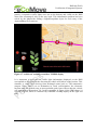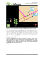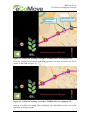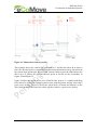
1
Cooperative Mobility Systems and Services for Energy Efficiency D450.48 (D4.8) Verification of Integrated Systems Sub-project No. SP4 Sub-project Title ecoFreight and Logistics Work package No. WP4.5 Work package Title Integration and Verification Task No. T 4.5.2 Task Title Test and verification Authors Till Uhrner, Philipp Themann, Oliver Vossen Institut für Kraftfahrzeuge Aachen, RWTH Aachen University Norddin El Ghouti, DAF Guillaume Vernet, Volvo Stephane Dreher, Nokia (Navteq) Florian Krietsch, PTV Dissemination level PU/PP/RE/CO CO File Name D450.48-D4.8-Verification of integrated system-v16 Due date 31.03.2013 Delivery date 23.08.2013 Abstract Deliverable D4.8 documents the integration and verification of the three main applications that were developed in SP4 “ecoFreight & Logistics” in the eCoMove project. Transport planners can optimise the routes of their fleet with respect to fuel consumption using the ecoTourPlanning application. Dynamic routing in the vehicle is supported by the Truck ecoNavigation application that respects the current status of the vehicle and includes traffic status information for the route choice. During the trip the driver is supported by the ecoDriverCoaching application that provides recommendations how to drive in the most fuel-efficient way by evaluating the driving style and traffic light status information. A post trip analysis helps the driver to D450.48 (D4.8) Verification of Integrated Systems improve his driving style for a long term period. This document summarises the requirements on the SP4 applications and explains their functional design. The integration of the ecoDriverCoaching applications in two demonstrator vehicles is described in detail. With focus on the component level the verification of the SP4 applications is documented for different test scenarios. Project supported by European Union DG INFSO ICT-2009-6.1, ICT for Clean and Efficient mobility Project reference IP Manager 19.08.2013 FP7-ICT-2009-4, IP Proposal – 247908 Jean Charles Pandazis, ERTICO – ITS Europe Tel : +32 2 400 0714 E-mail : [email protected] II Version 0.16 D450.48 (D4.8) Verification of Integrated Systems Control sheet Version history Version 0.1 0.3 Date 26.11.2012 05.12.2012 Main author Till Uhrner Till Uhrner 0.4 28.01.2013 Till Uhrner 0.5 04.03.2013 Guillaume Vernet 0.6 06.05.2013 Guillaume Vernet 0.7 0.8 10.06.2013 27.06.2013 Till Uhrner Guillaume Vernet 0.9 02.07.2013 Guillaume Vernet 0.10 0.11 15.07.2013 17.07.2013 Till Uhrner Norddin El Ghouti 0.12 0.13 20.07.2013 01.08.2013 Stephane Dreher Till Uhrner 0.14 08.08.2013 Till Uhrner 0.16 19.08.2013 Till Uhrner Prepared Reviewed Verified Authorized Circulation Name Till Uhrner (IKA) Franc Buve (Logica) Jean-Charles Pandazis (ERTICO) Jean-Charles Pandazis (ERTICO) Recipient Project partners European Commission 19.08.2013 Summary of changes Framework Feedback from CS meeting SP4 session included Chapter 2 removed, formatting Contributions on ecoDriverCoaching Further content on ecoDriverCoaching integration and verification Formatting Verification scenarios for ecoDriverCoaching Inclusion of revisions from Norddin El Ghouti on DAF truck SLAM integration notes Formatting Review actual content ecoNavigation Integration and Formatting Abstract and summary, ready for peer review Include peer review comments Date 08.08.2013 14.08.2013 23.08.2013 23.08.2013 Date of submission 23.08.2013 23.08.2013 III Version 0.16 D450.48 (D4.8) Verification of Integrated Systems Table of Contents 1 INTRODUCTION .................................................................................................. 9 1.1 1.2 1.3 PROJECT OVERVIEW .......................................................................................... 9 DELIVERABLE OVERVIEW.................................................................................. 9 DOCUMENT OVERVIEW ................................................................................... 11 2 DESIGN OF SP4 APPLICATIONS ................................................................... 12 2.1 DESIGN OF ECOTOURPLANNING ...................................................................... 12 2.1.1 ecoTourPlanning in the context of eCoMove........................................... 12 2.1.2 Functional requirements on ecoTourPlanning ........................................ 12 2.1.3 Applications and components interfering with ecoTourPlanning ........... 13 2.1.4 Comparison of ecoTourPlanning to state of the art solutions ................. 15 2.1.5 Design of functionality of ecoTourPlanning ............................................ 15 2.2 DESIGN OF TRUCK ECONAVIGATION ............................................................... 16 2.2.1 Truck ecoNavigation in the context of eCoMove ..................................... 16 2.2.2 Functional requirements on Truck ecoNavigation .................................. 16 2.2.3 Applications and components interfering with Truck ecoNavigation...... 18 2.2.4 Comparison of Truck ecoNavigation to state of the art solutions ........... 18 2.2.5 Design of functionality of Truck ecoNavigation ...................................... 18 2.3 DESIGN OF ECODRIVERCOACHING .................................................................. 19 2.3.1 ecoDriverCoaching in the context of eCoMove ....................................... 19 2.3.2 Functional requirements on ecoDriverCoaching .................................... 19 2.3.3 Applications and components interfering with ecoDriverCoaching ....... 21 2.3.4 Comparison of ecoDriverCoaching to state of the art solutions ............. 21 2.3.5 Design of functionality of ecoDriverCoaching ........................................ 21 3 INTEGRATION OF SP4 APPLICATIONS...................................................... 22 3.1 INTEGRATION OF ECOTOURPLANNING ............................................................. 22 3.2 INTEGRATION OF TRUCK ECONAVIGATION ...................................................... 22 3.3 INTEGRATION OF ECODRIVERCOACHING ......................................................... 22 3.3.1 Integration environment........................................................................... 22 3.3.2 Relevant Technical Components .............................................................. 22 3.3.3 Interfaces to the Integrated Application .................................................. 27 3.3.4 User manual and adaptability to test sites and simulations .................... 28 3.4 INTEGRATION OF SP4 APPLICATIONS IN DEMONSTRATOR VEHICLES ................ 29 3.4.1 Integration of SP4 applications in a long haul DAF transport truck ...... 30 3.4.2 Integration of SP4 applications in a Volvo distribution truck ................. 31 4 VERIFICATION OF SP4 APPLICATIONS .................................................... 32 4.1 VERIFICATION OF ECOTOURPLANNING ............................................................ 32 4.1.1 Verification of ecoTourPlanning for Test 1: Empty Roads Scenario ...... 32 4.1.2 Verification of ecoTourPlanning for Test 1: Traffic Scenario................. 33 4.2 VERIFICATION OF TRUCK ECONAVIGATION ..................................................... 34 4.2.1 Testing environment ................................................................................. 34 4.2.2 Verification of Truck ecoNavigation Results ........................................... 35 4.3 VERIFICATION OF ECODRIVERCOACHING ........................................................ 38 4.3.1 Electronic horizon data............................................................................ 39 4.3.2 Traffic light state and Traffic Signal Phase Data Message (TSPDM) .... 43 19.08.2013 4 Version 0.16 D450.48 (D4.8) Verification of Integrated Systems 4.3.3 Speed advice and SLAM........................................................................... 49 4.3.4 Sending ecoCAM and priority ................................................................. 53 4.3.5 Verification of Truck ecoDriverCoaching Test 1.7: ................................ 53 4.3.6 Verification of Truck ecoDriverCoaching Test 1.8: Title ........................ 54 4.3.7 Summary of Truck ecoDriverCoaching tests ........................................... 55 4.4 VERIFICATION OF SP4 APPLICATIONS IN DEMONSTRATOR VEHICLES ............... 55 4.4.1 Verification of SP4 applications in a long haul DAF transport truck ..... 55 4.4.2 Verification of SP4 applications in a Volvo distribution truck ................ 55 5 CONCLUSION ..................................................................................................... 56 6 REFERENCES ..................................................................................................... 57 6.1 6.2 ECOMOVE DELIVERABLES .............................................................................. 57 INTERNAL ECOMOVE REFERENCE DOCUMENTS .............................................. 57 19.08.2013 5 Version 0.16 D450.48 (D4.8) Verification of Integrated Systems FIGURES Figure 1: SP4 Deliverable Flow chart .......................................................................... 10 Figure 2: Architecture overview of SP4 and ecoTPS application ............................... 14 Figure 3: GUI of the trip planning TPS application – 1 .............................................. 15 Figure 4: GUI of the trip planning TPS application – 2 .............................................. 16 Figure 6: Interaction of components required by ecoDriverCoaching ........................ 23 Figure 7: Intersection topology - lane numbering........................................................ 25 Figure 8: Flow chart of positioning information.......................................................... 26 Figure 9: Components related to positioning ............................................................... 27 Figure 10: SP4 eCoMove platform .............................................................................. 29 Figure 11: Composition of the 800x600 screen ........................................................... 30 Figure 12: Vehicle data provider for DAF truck ......................................................... 31 Figure 13: Vehicle data provider for Volvo truck ....................................................... 31 Figure 14: ecoDriverCoaching screenshot - coasting before speed limit change ........ 40 Figure 15: ecoDriverCoaching screenshot: various speed limits in horizon ............... 41 Figure 16: ecoDriverCoaching screenshot: approaching a roundabout ....................... 42 Figure 17: ecoDriverCoaching screenshot: retarder advice ......................................... 43 Figure 18: ecoDriverCoaching screenshot: TSPDM display ....................................... 44 Figure 19: ecoDriverCoaching screenshot: TSPDM display when turning right ........ 45 Figure 20: ASN.1 grammar.......................................................................................... 46 Figure 21: Non-equipped and equipped traffic lights .................................................. 47 Figure 22: ecoDriverCoaching screenshot: TSPDM before non-equipped TL ........... 48 Figure 23: ecoDriverCoaching screenshot: TSPDM after non-equipped TL .............. 48 Figure 24: Illustration of advice profile ....................................................................... 50 Figure 25: ecoDriverCoaching screenshot - SLAM advice, good speed ..................... 51 Figure 26: ecoDriverCoaching screenshort - SLAM advice, too fast .......................... 51 19.08.2013 6 Version 0.16 D450.48 (D4.8) Verification of Integrated Systems TABLES Table 1: Requirements on ecoTPS and applied systems ............................................. 13 Table 2: Applications interfering with the TPS ........................................................... 14 Table 3: Requirements on Truck ecoNavigation ......................................................... 18 Table 4: Applications interfering with Truck ecoNavigation ...................................... 18 Table 5: Requirements on ecoDriverCoaching ............................................................ 21 Table 6: Applications interfering with ecoDriverCoaching......................................... 21 Table 7: Structure of LaneTurnMap.txt ....................................................................... 24 Table 8: Structure of ApproachMap.txt ....................................................................... 25 Table 9: Event types for IHorizonListener .................................................................. 27 Table 10: Main elements from ecoCooperativeHorizon .............................................. 28 Table 11: Test procedure SP4.4.1-2-1 ......................................................................... 35 Table 12: Test procedure SP4.4.1-2-2 ......................................................................... 36 Table 13: Test procedure SP4.4.1-2-3 ......................................................................... 37 Table 14: Test procedure SP4.4.1-2-4 ......................................................................... 38 Table 15: Test scenario SP4.4.2-1-7 ............................................................................ 38 Table 16: Test scenario SP4.4.2-1-8 ............................................................................ 39 Table 17: Organisation methods of the electronic horizon .......................................... 49 Table 18: Check methods for the Advice object .......................................................... 52 Table 19: Test procedure SP4.4.2-1-7 ......................................................................... 54 Table 20: Test procedure SP4.4.2-1-8 ......................................................................... 55 Table 21: Referenced eCoMove Deliverables ............................................................. 57 Table 22: Referenced internal eCoMove documents ................................................... 58 19.08.2013 7 Version 0.16 D450.48 (D4.8) Verification of Integrated Systems TERMS AND ABBREVIATIONS Abbreviation ADAS ADASRP API CAM eCH ecoTPS eDC GPS ITM LDT NTP POMA RSU SLAM SP TDB TPS TSPDM VPM 19.08.2013 Definition Advanced Driver Assistance System ADAS Research Platform Prototyping Environment Application Programming Interface Cooperative Awareness Message ecoCooperative Horizon ecoTourPlanning System ecoDriverCoaching Global Positioning System Intersection Topology Message Local Device Tree Network Time Protocol Positioning and Mapping Road Side Unit Speed and Lane Advice Message Sub-project Transfer Database Trip Planning System Traffic Signal Phase Data Message Vehicle Path Message 8 Version 0.16 D450.48 (D4.8) Verification of Integrated Systems 1 Introduction Deliverable D4.8 documents the approach of integrating several applications developed to reduce fuel consumption in the freight and logistics sector into demonstrator vehicles and subsumes the results of subsequent verification tests. It is part of the documentation of the eCoMove project, a European Commission cofunded integrated project under the 7th RTD Framework Programme. 1.1 Project Overview The eCoMove system is designed to tackle the problem of energy efficiency in road transport by applying the latest vehicle-to-infrastructure and vehicle-to-vehicle communication technologies to create an integrated solution comprising cooperative eco-driving support and eco-traffic management. The project aims to demonstrate that the combination of these new intelligent communication technologies can potentially lead to overall fuel savings and CO2 emission reductions of up to 20 %. The development of technologies and applications in eCoMove is structured into four sub-projects (SP) dealing with various aspects of the project. SP2 focuses on the development of the core technologies, SP3 on solutions for eco-driving support for car drivers, SP4 on applications for eco-driving support for trucks and eco-freight & logistics management and SP5 on applications for cooperative eco-traffic management. In particular, SP4 “ecoFreight & Logistics” comprises the following applications: 1.2 ecoTourPlanning: this application allows transport planners to determine the most fuel-efficient tours for all their vehicles based on a given set of transport orders to fulfil. Truck ecoNavigation: this application calculates the specific route and guides the driver to his next destination. It considers the configuration and the status of the vehicle and processes traffic status information to determine the most efficient route in terms of time and fuel. ecoDriverCoaching: this application supports the driver while following the calculated route to drive in the most fuel-efficient way. The onboard ecoDriverCoaching is accompanied by an ecoDriving Trainer and an ecoFleet Business component in the back-office for post-trip analysis. Deliverable Overview D4.8 is the final deliverable in SP4 and summarises the verification of the integrated applications. The deliverables in SP4 are structured as illustrated in Figure 1. 19.08.2013 9 Version 0.16 D450.48 (D4.8) Verification of Integrated Systems Figure 1: SP4 Deliverable Flow chart In [D4.1] stakeholders and users of the eCoMove system are identified. SP4 will focus on the transport planner in the back-office of the transport company and the driver of the truck. Inefficiencies caused by the users are transformed to specified use cases. On this basis the SP4 system requirements are derived. [D4.2] contains the architecture and system specification of SP4 ecoFreight & Logistics applications. It describes the interdependencies with other SPs and how the architecture design covers the use cases and requirements defined in D4.1. The development of the three SP4 main applications is described in deliverables D4.3-D4.5, at which [D4.3] documents the development of the logistics back-office applications and the interdependencies with the City Logistics Management system, [D4.4] documents the development of the Truck ecoNavigation application and [D4.5] documents the development of the ecoDriverCoaching application that is a three part system focusing on pre-trip, on-trip and post-trip scenarios. 19.08.2013 10 Version 0.16 D450.48 (D4.8) Verification of Integrated Systems The system integration in the two demonstrator vehicles is described in deliverables D4.6 and D4.7, at which [D4.6] deals with the DAF Truck demo vehicle and [D4.7] deals with the Volvo demo vehicle. References to deliverables of other SPs are mentioned separately in this document. 1.3 Document Overview The following section provides a short summary of the different chapters in order to give an overview of the document structure: In Chapter 2 the design of the SP4 applications in the eCoMove project as well as the functional requirements and the connection to other components in high level architecture is described. In Chapter 3 the integration of the SP4 applications is described with focus on the component level. In addition to D4.6 and D4.7 the integration in the particular demonstrator vehicles is referenced briefly. Chapter 4 follows the structure of Chapter 3, where the verification of the SP4 applications with focus on the component level is described. Again the verification in the particular demonstrator vehicles is described in addition to D4.6 and D4.7. Chapter 5 summarises the integration and verification procedure of the SP4 applications. 19.08.2013 11 Version 0.16 D450.48 (D4.8) Verification of Integrated Systems 2 Design of SP4 applications This chapter illustrates the purpose of the three applications that are developed in SP4 “ecoFreight & Logistics”. In- and outputs of the components as defined in the system architecture are subsumed. Additional definitions and the design of functionalities of the applications are described. 2.1 Design of ecoTourPlanning This application allows transport planners to determine the most fuel-efficient tours for all their vehicles based on a given set of transport orders to fulfil. In general, trip planning systems (TPS) generate trips for a certain set of transport orders, vehicles and drivers, following the idea of a travelling sales man problem. Main optimisation criteria are time followed by payload of the vehicle. This does not consider the behaviour of a truck under certain conditions and the most fuel-efficient way of driving. Finding an optimized stop sequence under given restrictions and the right vehicle under the right conditions with an optimum payload is the main objective for the ecoTourPlanning system (ecoTPS). Note: The following sections are an excerpt from deliverable [D4.3] describing the ecoTourPlanning system. 2.1.1 ecoTourPlanning in the context of eCoMove The ecoTPS allows transport planners to determine daily or weekly trips of all vehicles based on a given set of transport orders. The system considers the fuel consumption behaviour of each vehicle under the applicable driving and loading conditions. and calculates the most efficient ecoTrip for each of the vehicles. These ecoTrips are sent to the vehicle and processed further by the Truck ecoNavigation and the ecoDriverCoaching application. The ecoTPS processes given transport orders, uses dedicated eco trip planning algorithms and mid-term traffic information coming from the SP5 Traffic Information Server. The result is a set of planned trips. Each trip will be electronically requested for acceptance at the City Logistic Management Centre. Trips that have been granted access to the city will be sent to the in-truck navigation system. During the execution of the transport task the planner can change the trip stop points to handle exceptions. An updated trip can be sent to the in-vehicle client. When the trip is finished, the application allows a comparing analysis between pre-calculated emissions and real mission data. Hence, ecoTPS addresses transport planners and truck drivers. 2.1.2 Functional requirements on ecoTourPlanning The functional requirements are listed in Table 1 according to [RQecoTPS]: REQ NR. Description Req-SP4-30001 The trip planning system shall propose the back-office planner of the logistic company a simplified graphical environment. 19.08.2013 12 Version 0.16 D450.48 (D4.8) Verification of Integrated Systems REQ NR. Description Req-SP4-30002 Historic traffic data and mid-term prediction data from the SP5 ‘Transport Information Server (SP5 ecoATS) provided via a dedicated interface is taken into account. Req-SP4-30003 The trip planning system shall automatically allocate transport orders to trips, following a dedicated CO2 emission minimization planning algorithm. Req-SP4-30004 The trip planning system shall calculate for each planned trip a CO2 forecast. Req-SP4-30005 The trip planning system shall display information (stop points, mission time, ect.) on the planned trips to the planner. Req-SP4-30006 The back-office planner shall be able to send the planned trips electronically to the ‘City Logistic Management Centre’ and request access. Req-SP4-30007 Electronic trip list instruction transfer from the trip planning system to the invehicle routing client. Req-SP4-30008 Back office planner can interact during mission, thus send updates to the invehicle client. Req-SP4-30009 CO2 footprint comparison for forecast and ex-post situation Req-SP4-30010 The application allows Public Authority officers to define the environmental parameters basing on which to authorize the ecoTrip (CityLogistics). Req-SP4-30011 The application allows Public Authority officers to authorize or not an ecoTrip according to its policy conformance (CityLogistics) Req-SP4-30012 The application provides an interface allowing a logistics company planner to communicate to the Public Authority the parameters describing a goods distribution mission in order to ask for the authorization Req-SP4-2-01 ecoNavigation must accept an ecoTrip or separate ecoTrips from the back-office system. This implicitly means: ecoNavigation must take arrival time restrictions into account. ecoNavigation must take destinations order restrictions into account eCoNavigation must take a combination of travel time and destinations order into account Req-SP4-2-02 ecoNavigation should make use of waypoints from the back-office system. Req-SP4-2-03 ecoNavigation should make use of an updated ecoTrip or ecoTrip from the back office. Req-SP4-2-23 ecoNavigation should inform the back office about the calculated arrival time. Table 1: Requirements on ecoTPS and applied systems 2.1.3 Applications and components interfering with ecoTourPlanning Applications that interfere with the ecoTPS are in particular SP4 Truck ecoNavigation, SP4 City Logistics Management and SP4 ecoDriverCoaching as listet in Table 2. 19.08.2013 13 Version 0.16 D450.48 (D4.8) Verification of Integrated Systems Application name Developed in Truck ecoNavigation City Logistics Management ecoDriverCoaching SP4 SP4 SP4 Table 2: Applications interfering with the TPS According to the functional architecture there is also a link between the applications of SP4 and SP5 Traffic Management and Control. The following data is required from there: Traffic state predictions that describe the traffic situation on a short (next 15min) (optional) / mid (day level) / long-term (next days) Traffic status that reports the actual situation (e.g. traffic jams) Network optimal routes that allow SP5 to overrule in-vehicle Truck ecoNavigation and distribute traffic equally Traffic signal states (e.g. traffic light status) and local advices (e.g. lane choice, speed) that are incorporated by the ecoDriverCoaching Figure 2 visualizes the interaction of applications connected to the back-office system. Figure 2: Architecture overview of SP4 and ecoTPS application 19.08.2013 14 Version 0.16 D450.48 (D4.8) Verification of Integrated Systems 2.1.4 Comparison of ecoTourPlanning to state of the art solutions The generic functions used in the ecoTPS are not new, but the way they are linked and modified by the application. Considering their core functionality all of the above mentioned applications already exist. Trip planning systems are used by a lot of transport companies, more and more Fleet Management Systems monitor driver behaviour and truck-specific navigation is already state of the art. These applications address all the different phases of a trip but they still miss the cooperative approach and do not always focus on decarbonisation. Trip Planning Systems generate trips for a certain set of transport orders, vehicles and drivers taking into account given restrictions. Main optimisation criteria are time followed by payload of the vehicle. This does not consider the behaviour of a truck under certain conditions and the most fuel-efficient way of driving as it is done in the ecoTPS. 2.1.5 Design of functionality of ecoTourPlanning The GUI of the ecoTPS application is a set up out of three components: a ribbon, a navigation tree and a workspace which are designed to be used on a multi-monitor workstation. The navigation tree displays all available functions. If selected to appear in the workspace, each function shows other items to choose in the ribbon. Some functions display more than one window in the workspace. If it holds the sign of a small pin this window can be pulled out and moved to whatever size and place is convenient. Figure 3 and Figure 4 illustrate the GUI of the ecoTPS. Figure 3: GUI of the trip planning TPS application – 1 19.08.2013 15 Version 0.16 D450.48 (D4.8) Verification of Integrated Systems Figure 4: GUI of the trip planning TPS application – 2 The ecoTPS includes a lot of different functions to personalize and to customize the way orders are planned. It can incorporate different users with different rights as well as several different vehicles, driver profiles and positions. Thus it is able to conduct an optimised trip planning with many options to add requirements and restrictions. The detailed description of the design and the functionality of ecoTPS can be found in deliverable [D4.3]. 2.2 Design of Truck ecoNavigation This application calculates the specific route and guides the driver to his next destination. It considers the configuration and the status of the vehicle and processes traffic status information to determine the most efficient route in terms of time and fuel. A detailed description of the design and role of Truck ecoNavigation is available in [D4.4]. 2.2.1 Truck ecoNavigation in the context of eCoMove The Truck ecoNavigation calculates the route to the next destination (as identified by its mission profile worked out by ecoTour Planning application [D4.2]) and guides the driver to it. Thereby it considers the configuration and status of the vehicle and processes necessary traffic status information to determine the most efficient route in terms of travel time and fuel consumption. 2.2.2 Functional requirements on Truck ecoNavigation 19.08.2013 16 Version 0.16 D450.48 (D4.8) Verification of Integrated Systems 23 functional requirements have been defined for the ecoNavigation component. They have been classified into types of input (back-office, driver, historic map, vehicle, V2I & V2V), route calculation functionality, optimization and calculation time constraints, route replacement and output to the driver. Table 3 gives a short overview of the requirements that are elaborated in detail in [D4.4]. REQ NR. Description SP4-2-01 ecoNavigation must accept an ecoTour or separate ecoTrips from the back-office system. SP4-2-02 ecoNavigation should make use of waypoints from the back-office system. SP4-2-03 ecoNavigation should make use of an updated ecoTour or ecoTrip from the back office. SP4-2-04 User should be able to select a destination or an intermediate location along the route; ecoNavigation should be usable also without a back office or when the connection to the back office is unavailable. SP4-2-05 When the vehicle leaves the route, the route is recalculated within a short time. (see req. 22). Some tolerance for small deviations to the route must be incorporated to avoid unnecessary recalculation SP4-2-06 ecoNavigation must be able to calculate a route advice while taking into account these limiting vehicle parameters: weight, width, height, length, load conditions, vehicle engine category and other restrictions available in the ecoMap. SP4-2-07 ecoNavigation must be able to calculate a route advice while taking into account these limiting vehicle parameters: weight, width, height, length, load condiations, vehicle engine category and other restrictions available in the ecoMap. SP4-2-08 ecoNavigation should make use of dynamic traffic information and situational data. SP4-2-09 ecoNavigation should make use of floating vehicle data from other vehicles. SP4-2-10 ecoNavigation should be able to incorporate route advice from a traffic centre. SP4-2-11 ecoNavigation must generate a legal route to the destination. SP4-2-12 ecoNavigation should warn of impossible routes. SP4-2-13 ecoNavigation must be able to calculate a route advice that is primarily optimised for travel time. SP4-2-14 ecoNavigation must be able to calculate a route advice that is primarily optimised for fuel consumption / CO2 emissions. SP4-2-15 ecoNavigation should make use of vehicle parameters for fuel optimization. SP4-2-16 Optionally, the route can be optimized for a configurable combination of fuel consumption and travel time. SP4-2-17 A route calculation should take at most one minute for a route up to 500 km. SP4-2-18 A route recalculation due to new/updated information should take at most one minute for a route up to 500 km. SP4-2-19 A route recalculation after leaving the route should take at most 10 seconds. SP4-2-20 When new floating vehicle data or dynamic traffic information is available, the route is recalculated. If the newly calculated route shows a significant fuel saving compared to the previous one, it replaces the previous route for further guidance. SP4-2-21 The fuel savings and time saving threshold for switching to a new route should be configurable. SP4-2-22 ecoNavigation guides the driver along the ecoRoute and informs about impending manoeuvres. 19.08.2013 17 Version 0.16 D450.48 (D4.8) Verification of Integrated Systems REQ NR. Description SP4-2-23 ecoNavigation guides the driver along the ecoRoute and informs about impending manoeuvres. Table 3: Requirements on Truck ecoNavigation 2.2.3 Applications and components interfering with Truck ecoNavigation Within the eCoMove ecosystem, the ecoNavigation component interacts with several other applications from SP2, SP3 and SP4. These applications are listed in Table 4. Application name Developed in ecoMap ecoCooperativeHorizon ecoTourPlanning ecoDriverCoaching ecoATS SP2 SP3 SP4 SP4 SP5 Table 4: Applications interfering with Truck ecoNavigation The behaviour of Truck ecoNavigation in interaction with the listet applications is described in detail in [D4.4]. 2.2.4 Comparison of Truck ecoNavigation to state of the art solutions The Truck ecoNavigation application implemented in eCoMove SP4, similarly to the dynamic ecoNavigation for vehicles developed in SP3, contributes to the overall eCoMove objective via improved route calculation as compared to state-of-the-art navigation systems: The estimated fuel consumption is derived from the evaluation with GPS probe data in conjunction with vehicle specific fuel consumption models. Consideration of road attributes such as slopes along each link Consideration of speed information received from the Traffic Management Centre Consideration of energy (fuel) consumption as obtained from learned consumption data. Consideration of trip Data from Fleet Planning. Thus, the route obtained provides a more realistic prediction of energy consumption for route alternatives;, which enables the user to gain real energy cost savings and increases his willingness to choose for the calculated ecoRoute. 2.2.5 Design of functionality of Truck ecoNavigation The implementation of the Truck ecoNavigation prototype follows the general architecture presented in [D4.4]. The input and output objects and interfaces, as well 19.08.2013 18 Version 0.16 D450.48 (D4.8) Verification of Integrated Systems as the Routing Engine, have been implemented according to the general eCoMove Architecture. The components are built around NAVTEQ’s ADAS Research Platform Prototyping Environment (ADASRP). The Routing Service is integrated as a native component in ADASRP with an eCoMove specific cost function. The Routing Service is controlled by an ecoNavigation plug-in of ADASRP which is responsible for managing the Input/Output of the Service, 2) triggering Route calculation and 3) handling rerouting requests or quick re-routing based on existing routes. The Routing component accesses the eCoMap which is implemented in the eCoMove OSGI environment [D2.6]. 2.3 Design of ecoDriverCoaching This application supports the driver while following the calculated route to drive in the most fuel-efficient way. The onboard ecoDriverCoaching is accompanied by an ecoDriving Trainer and an ecoFleet Business component in the back-office for posttrip analysis. Note: The following section is an excerpt from deliverable [D4.5] describing the ecoDriverCoaching application. 2.3.1 ecoDriverCoaching in the context of eCoMove ecoDriverCoaching is an application helping the truck driver to drive fuel efficiently by providing him anticipative and corrective advices based on current vehicle state, electronic horizon and cooperative information received from the infrastructure. It is the equivalent of ecoDriverSupport developed for passenger cars in SP3 (one implementation by each OEM Ford, Fiat, and BMW). In SP4, ecoDriverCoaching was developed by Volvo and integrated in both Volvo and DAF test trucks. 2.3.2 Functional requirements on ecoDriverCoaching In order to derive the system specifications of ecoDriverCoaching, 33 functional requirements have been defined. They are classified into pre-trip, on-trip and post-trip driver coaching plus requirements for the ecoFleetBusiness application. Table 5 gives a short overview of the requirements that are elaborated in detail in [D4.1]. REQ NR. Description SP4-1A-0001 The training system shall propose the driver a simplified cab environment. SP4-1A-0002 The training system shall display to the driver a virtual environment with selected roads and traffic conditions. SP4-1A-0003 The training system shall display to the driver the ecoDriver coaching system on his HMI similar to on a real trip. SP4-1A-0004 The training system shall use the language of the driver. SP4-1B-0001 Before starting the trip, the system shall remind the driver to do the necessary daily checks on the vehicle. SP4-1B-0003 The on-board application shall display eco-driving recommendations in a timely appropriate manner depending on the real-time driving situation. 19.08.2013 19 Version 0.16 D450.48 (D4.8) Verification of Integrated Systems REQ NR. Description SP4-1B-0004 Only information about factors the driver can affect while driving shall be communicated on-board via the eco-coaching system to the driver. SP4-1B-0005 The eco-coaching system must not jeopardize safety. SP4-1B-0006 The on-board application shall be internationalized to fit the driver language setting. SP4-1B-0007 The eco-coaching system must not cause (cognitive) overload to the driver. SP4-1B-0008 The system shall monitor the driving performance and display key performance indicators to the driver while driving. SP4-1B-0009 The factors the eco-coach system uses and refers to must be comprehended by the driver. SP4-1B-0011 Feedback and eco-coaching to the driver about his/her performances shall be phrased in a supportive and positive way to ensure good driver acceptance. SP4-1B-0012 Eco-driving advices should not be displayed during critical situations detected by the system. SP4-1B-0013 Eco-coach HMI shall communicate to the driver through ways as appropriate as possible. SP4-1B-0014 The eco-coaching shall be able to adapt to the individual drivers’ driving pattern and driving progress in order to provide the optimal eco-coaching. SP4-1B-0015 The eco-coaching system should get real-time data to adapt to the specific driving situations. SP4-1B-0016 The on-board eco-coaching HMI shall be configurable by driver. SP4-1B-0017 The eco-coaching system shall be configurable for various vehicle configurations. SP4-1B-0018 At the end of his trip, the driver shall review his driving profile and inputs comments to explain possible exceptions and external circumstances (e.g. weather conditions, maintenance problem,…). SP4-1B-0019 The driving profile is sent from the vehicle to the back-office after the trip. SP4-1B-0020 The system shall try to take into account external circumstances when computing driver evaluation. SP4-1C-0001 ecoFleetBusiness application shall receive from registered vehicles the driving profiles. SP4-1C-0002 ecoFleetBusiness shall enable fleet manager to log in and manage their personal settings. SP4-1C-0003 Fleet managers shall see statistics and trends of their fleet. SP4-1C-0004 Fleet managers shall see statistics and trends on fuel consumption for individual drivers. SP4-1C-0005 The system shall respect privacy legislations applied in different countries. SP4-1C-0006 ecoFleetBusiness shall enable drivers to log in and manage their personal settings. SP4-1C-0007 The driver shall be able to extract a post-trip report from the system. SP4-1C-0008 The driver shall be able to assess his eco-driving performance. SP4-1C-0009 ecoFleetBusiness system shall have sufficient storage capacities for storing historical driving profiles. SP4-I-0003 The ecoDriver Coaching requires from SP5: Traffic signal states; Local advices that are relevant for the current driving situation. SP4-I-0004 The ecoDriver Coaching requires information about the actions performed by other vehicles wihtin proximity and driving into the same direction. 19.08.2013 20 Version 0.16 D450.48 (D4.8) Verification of Integrated Systems Table 5: Requirements on ecoDriverCoaching 2.3.3 Applications and components interfering with ecoDriverCoaching Within the eCoMove ecosystem, the on-board ecoDriverCoaching software interacts with several other applications from SP2, SP3 and SP4. These applications are listed in Table 6. Application name Developed in ecoMap ecoCooperativeHorizon ecoMonitoring (sender/receiver/mapfeeder) LocalDeviceTree and TripDataSet Truck ecoNavigation SP2 SP3 SP3 SP2/SP3 SP4 Table 6: Applications interfering with ecoDriverCoaching The back-office part of ecoDriverCoaching has no interaction with other eCoMove components. As it is independent from the rest of the eCoMove system and has been described in [D4.5], it will not be further discussed in this deliverable. 2.3.4 Comparison of ecoDriverCoaching to state of the art solutions Current eco-driving components on the market work purely on vehicle data, only few consider map information. The innovation of ecoDriverCoaching within eCoMove lies in the cooperation between vehicles and infrastructure and in taking into consideration three levels of functionalities: Advices based on vehicle data only (e.g. pedal usage or engine RPM) Advices based on horizon data (slopes, curves, speed limits, stops, etc.) Cooperative advices based on V2V and V2I communication The availability of higher level data will lead to more specific recommendations, as the driving situation can be identified more precisely by the ecoDriverCoaching application. Nevertheless, it is still able to display basic recommendations, if only vehicle data is available. 2.3.5 Design of functionality of ecoDriverCoaching The functionality of ecoDriverCoaching comprises the functionalities of the on-board components, of the user interface and of the internationalisation capabilities. For a detailed description of these functionalities it is referred to [D4.5]. 19.08.2013 21 Version 0.16 D450.48 (D4.8) Verification of Integrated Systems 3 Integration of SP4 applications In this chapter the integration of the SP4 applications is described with focus on the component level. The integration in the particular demonstrator vehicles is described in chapter 3.4. 3.1 Integration of ecoTourPlanning The integration of the ecoTourPlanning system is described in [D4.3]. 3.2 Integration of Truck ecoNavigation The integration of the Truck ecoNavigation is described in [D4.4]. 3.3 Integration of ecoDriverCoaching The following sections describe the integration of the ecoDriverCoaching application. 3.3.1 Integration environment The ecoDriverCoaching on-board application is integrated in the eCoMove truck platform. Both Volvo and DAF trucks use a very similar setup, consisting of: 3.3.2 Vehicle router (Q-Free), handling communications and positioning Vehicle Application Unit: Windows based embedded computer running NAVTEQ ADASRP and OSGi framework with eCoMove software components (bundles) Touch screen for user interface Vehicle gateway (OEM specific) to access vehicle data Relevant Technical Components The ecoDriverCoaching application is at the end of a chain of components processing data, especially for the treatment of ecoMessages. This process is depicted in Figure 5. 19.08.2013 22 Version 0.16 D450.48 (D4.8) Verification of Integrated Systems Figure 5: Interaction of components required by ecoDriverCoaching Note that this diagram does not show the eCoMoveLogger and the eCoMoveReplay for the sake of clarity. The eCoMoveLogger stores the content of the Local Device Tree and incoming ecoMessages in a local SQLite database. The treatment path for ecoMessages and positioning information is detailed in the following sections. 19.08.2013 23 Version 0.16 D450.48 (D4.8) Verification of Integrated Systems ecoMessage processing: Once in the application unit, an ecoMessage goes through several components before being usable by ecoDriverCoaching. These steps are numbered 1 to 4 in the above diagram. 1. SP2 ecoMessages to SP3 ecoMonitoring_receiver The ecoMessages layer (API, and Q-Free implementation) has decoded the ASN.1 messages and turned them into corresponding Java objects. An OSGi event is triggered by SP2 ecoMessage layer upon reception. The ecoMonitoring_receiver is registered as an OSGi EventHandler and is notified of these events, hence getting access to the Java ecoMessage objects. 2. SP3 ecoMonitoring_receiver to SP3 MapFeeder This step is a forwarding of the Java ecoMessage objects to the MapFeeder via an ecoMessageListener API bundle. CTAG, who developed these components, used this design to treat several ecoMessages listeners in the same way: MapFeeder and eCoMoveLogger. 3. SP3 MapFeeder to SP2 ecoMap This is the most complex step, as it is actually where the ecoMessage content is converted from ASN.1 (or its Java equivalent) to a map object stored in the ecoMap. It is important to say that Traffic Signal Phase Data Message (TSPDM) and Speed and Lane Advice Message (SLAM) ecoMessages are relying on intersection topology messages (ITM). ITM messages are sent by RSUs in Helmond but NAVTEQ decided that since there were only a rather limited number of RSUs and hence different intersections topology, it would be better not to implement an ITM decoder but use a static mapping files. This is achieved by two CSV files used by MapFeeder, which are specific for NAVTEQ implementation of ecoMap/ecoCooperativeHorizon (as it refers to NAVTEQ road element ids): LaneTurnMap.txt: contains the mapping of before/after road element ids for all possible lanes & manoeuvers at an intersection ApproachMap.txt: contains the definition of the different lanes composing an intersection (each turn direction) in terms of ADASRP road elements composing them. The structure of each file and some extracts are listed in Table 7 and Table 8. Intersection id Lane id Turn direction Id In (link before) Direction before Id out (link after) 701 701 0010 0080 RIGHT STRAIGHT 73984707 61138360 + 54602419 73984709 Table 7: Structure of LaneTurnMap.txt 19.08.2013 24 Version 0.16 D450.48 (D4.8) Verification of Integrated Systems This means that at intersection 701, lane 10 turns right, from road element id 73984707 (negative direction) to road element 54602419. Intersection id Approach id Excess start Excess end List of approach links with direction 701 702 3008 1002 192.81 13.26 21.74 24.32 +6113836 -54609191, -55043106, -68364586, -68364587 Table 8: Structure of ApproachMap.txt The approach length of lane 1002 at intersection 702 is composed of 4 NAVTEQ road elements. The sum of their length, minus the excess distance at start and end yields the total approach length as used as reference in SLAM messages. The lane numbering scheme designed by Peek is described in [HelMsg], which contains also information on Helmond infrastructure messages. Figure 6 below shows the overview of lane numbering. For example, approach lane 3008 is going straight west to east, while for example approach lane 1001 is turning right, east to north. Figure 6: Intersection topology - lane numbering ApproachMap is used for SLAM TimeAdvice to know the length of each approach lane (by summing the length of all road elements listed minus excess start and end). Indeed the ASN.1 grammar specifies a percentage of a total approach length. When putting this information on the map, it needs to be converted to a distance in meters before the traffic light. 4. SP2 ecoMap to SP3 ecoCooperativeHorizon In SP4the NAVTEQ implementation of ecoMap and ecoCooperativeHorizon is used, which are running in ADAS RP. In principle, the fourth step is to make the 19.08.2013 25 Version 0.16 D450.48 (D4.8) Verification of Integrated Systems information available in the ecoMap, specifically on road elements that are located on the forecast most probable path. There are however some subtleties about this, especially for dynamic map data changing after an electronic horizon has been calculated. Section 4.3.2 describes the issues encountered during integration and how they were solved. In this chain of component processing the ecoMessages change representation in the sense of a Java object (from ASN.1 equivalent in step 1 to profile of Advice objects at the ecoCooperativeHorizon level - step4). In this process, not all information from the original message is conveyed all the way to the ecoCooperativeHorizon objects, in particular the message generation timestamp, which causes difficulties for SLAM time advice interpretation. For this reason, an alternative direct processing of SLAM by ecoDriverCoaching was implemented (dashed link in Figure 5). This will be further explained in section 4.3.3. Positioning information: Note: The following section is an excerpt of chapter “7.4.3 Vehicle Positioning” in deliverable D4.5 [D4.5]. A GPS receiver is contained in the Q-Free router. On the application unit, the bundle qfree_poma_gpsd-1.0.3 retrieves the GPS information from the router (using gpsd) and posts POMA events using OSGi EventAdmin service. POMA is an API stemming from the CVIS project.It is a short name for POsitioning and MApping. Further information on POMA can be found in the eCoMove Developer Handbook [eDH]. During the development phase in eCoMove and the introduction of eCoMoveLogger and eCoMoveReplay, it appeared necessary to have the positioning information available in the Local Device Tree. This is achieved with the OSGi bundle POMA2LDT developed by Volvo and shared with the consortium on SP4 TRAC platform. This OSGi bundle listens to POMA events to be informed of new positioning information and writes it accordingly in the proper LDT cells (7 cells in sub-tree /Vehicle/Positioning/GPS/, see [TDS]). Figure 7 shows the flow of positioning information. Figure 7: Flow chart of positioning information The software and hardware components involved in the process of the positioning are listed in Figure 8. 19.08.2013 26 Version 0.16 D450.48 (D4.8) Verification of Integrated Systems Figure 8: Components related to positioning 3.3.3 Interfaces to the Integrated Application Deliverable [D4.5] contains a detailed description on how ecoCooperativeHorizon is used by the ecoDriverCoaching application in section 7.4.2. The following text is an excerpt from this section. The ecoDriverCoaching bundle com.volvo.ecomove.obu.edc registers as an IHorizonListener service in the OSGi service registry. The implementation of the ecoCooperativeHorizon API, in our case from NAVTEQ, notifies all IHorizonListener upon 3 types of events as listet in Table 9. Event Description onContentChanged The data content of the horizon has changed (maybe the vehicle position as well), while the path itself (the list of road segments) is unchanged. The horizon has changed, including the path, data content, and the vehicle position. The position of the vehicle along the horizon has changed, without any horizon data changes. onPathChanged onPositionChanged Table 9: Event types for IHorizonListener With this mechanism, the ecoDriverCoaching algorithm is notified and can access the horizon and all elements on it. The most important features from the 19.08.2013 27 Version 0.16 D450.48 (D4.8) Verification of Integrated Systems ecoCooperativeHorizon used by the ecoDriverCoaching algorithm are listed in Table 10. eCH element Description Vehicle offset getVehicleOffsetCM() Get the position of the vehicle on the horizon. This is required to know the relative distance to any object on the horizon. Curvatures getCurvatures() Get a profile for the road curvature. This is used by the eDC to compute safety speeds to approach sharp curves. Slopes getSlopes() Get a profile for the slope of the road, in percent. This is used by eDC for hill driving advices. Speed limits getSpeedLimits() Get the legal speed limit profile. This is used by eDC to compute speed and coasting advices. Traffic signs getTrafficSigns() Get all traffic signs along the horizon valid in travel direction. This is used by eDC to identify situations where anticipated deceleration is advised, and in HMI event display. Traffic lights getTrafficSignals() Get all traffic signals along the horizon with the current and near-future states. Used for information related to traffic light approach. Advices from SP5 getAdvice() Get all speed/time/lane advices along the horizon in travel infrastructure direction. Surrounding vehicles getVehicles() Get all vehicles currently present along the horizon in travel direction. Table 10: Main elements from ecoCooperativeHorizon More information on the ecoMap and the ecoCooperativeHorizon can be found in deliverables [D2.6] (ecoMap) and [D3.5] (ecoCooperativeHorizon). 3.3.4 User manual and adaptability to test sites and simulations The use of ecoDriverCoaching is described in deliverable [D4.5]. 19.08.2013 28 Version 0.16 D450.48 (D4.8) Verification of Integrated Systems 3.4 Integration of SP4 applications in demonstrator vehicles As mentioned in section 3.3.1, Volvo and DAF have a very similar setup for the eCoMove system and its integration into the test trucks. Figure 9 below shows the basic setup of the SP4 eCoMove platform. Figure 9: SP4 eCoMove platform The setup consists of a communication unit (Q-Free router), an application unit (running eCoMove facilities and SP4 applications) attached to a touchscreen and an OEM specific vehicle gateway to access the truck live data. These vehicle gateways are described in sections 3.4.1 and 3.4.2 of this deliverable, whereas two separate deliverables give a general presentation of the DAF [D4.6] and Volvo [D4.7] demonstrator trucks. Two important elements worth to document for the common SP4 integration are: System time synchronization with the Network Time Protocol (NTP) Window positioning with AutoHotKey System time synchronization with NTP: The Q-Free router synchronises its system clock with GPS signals. It runs an NTP server, which can be used by other devices on the vehicle LAN to synchronize their system time over the network. On the application unit running a Windows operating system, the program “NetTime” (www.timesynctool.com) was used to connect to the NTP server on the Q-Free router. The standard Windows clock menu has NTP support but did not contain enough configuration options and debug outputs. Window positioning with AutoHotKey: The integration of ecoDriverCoaching HMI and Truck ecoNavigation (ADASRP based) on the same screen required some modifications, as these are two applications with different windows. The ecoDriverCoaching HMI is a frameless Java Spring 19.08.2013 29 Version 0.16 D450.48 (D4.8) Verification of Integrated Systems based window, whereas ADASRP is a desktop application written in C++ and using the Microsoft Foundation Classes library. The solution found is AutoHotKey (www.autohotkey.com), a script-based automation program that allows performing a wide range of actions and attaching them to hotkeys (keyboard shortcuts). Among these possible actions, only window manipulations were used. More precisely, the ADASRP main window is moved in such a way that only its map part is visible on the right hand side of the screen as shown in Figure 10. Figure 10: Composition of the 800x600 screen The menu bar of the ADASRP main window (orange) is out of the visible screen portion and the ADASRP navigation guidance plugins “GuidanceSign” and “GuidanceText” (red) were configured to be detached from the ADASRP main window. They are borderless and were positioned on the bottom right part of the screen. The ecoDriverCoaching Swing window (blue) was finally placed on the left hand-side of the screen and brought to foreground to cover ADASRP main window borders. Textual popups generated by ecoDriverCoaching are realized with semi-transparent window (Swing JWindow) positioned on top of the map part. They fade away after being displayed for a few seconds. 3.4.1 Integration of SP4 applications in a long haul DAF transport truck Compared to the “generic SP4 setup”, the main characteristic of the integration within the DAF test truck is the OEM specific vehicle data provider. For this purpose, the 19.08.2013 30 Version 0.16 D450.48 (D4.8) Verification of Integrated Systems DAF Vehicle Gateway uses the CANcase from vector hardware adapted to receiving and decoding the J1939 data format from the vehicle CAN bus and forward the content to the application unit. A DAF-specific vehicle provider bundle further processes the received content of the packets and writes the vehicle data inside the LDT. Figure 11 depicts the process. Figure 11: Vehicle data provider for DAF truck 3.4.2 Integration of SP4 applications in a Volvo distribution truck Compared to the “generic SP4 setup”, the main characteristic of the integration within the Volvo test truck is the OEM specific vehicle data provider. For this purpose, the Volvo Telematics Gateway was used with custom software to transmit vehicle data in UDP datagrams to the application unit. A Volvo-specific vehicle provider bundle decoded these datagram and wrote the vehicle data inside the LDT. Figure 12 depicts the process. Figure 12: Vehicle data provider for Volvo truck In contrast to the DAF truck, the Volvo Telematics Gateway is equipped with an additional GPS receiver. Via a configuration setting it is possible to use this source of positioning instead of the Q-Free router GPS receiver. 19.08.2013 31 Version 0.16 D450.48 (D4.8) Verification of Integrated Systems 4 Verification of SP4 applications In this chapter the verification of the SP4 applications is described with focus on the component level. The verification in the particular demonstrator vehicles is described in chapter 4.4 and deliverables [D4.6] and [D4.7]. 4.1 Verification of ecoTourPlanning The ecoTourPlanning system covers order planning of transport orders and an optimization. The main target is to reduce fuel consumption by a reduction of the planned fleet-km driven. In two test cases characteristic scenarios, one with and the other without traffic data, are tested. Both scenarios take fleet restrictions (e.g. availability times, opening hours) into account. Furthermore ecoTPS can react to traffic information and use this for strategic scenarios. Note: The following sections are an excerpt from deliverable [D4.3] describing the ecoTourPlanning system. 4.1.1 Verification of ecoTourPlanning for Test 1: Empty Roads Scenario The ecoTPS system has to be set up correctly. This includes either a software installation of the ecoTPS suite at the testing company or a centralized installation, provided via a presentation server. 4.1.1.1 Preparation of Hard- and Software For a software installation the following hardware is recommended: Fast processor, quad core with +3GHz is recommended 12GB RAM are recommended 15GB HDD are recommended Transfer Database (TDB) requires network access; specification of TDB in Appendix B For a centralized software execution, mainly internet connection bandwidth is important. The application in this case is deployed in the PTV DMZ server environment. The whole interaction takes place via an internet based presentation server (Software as a Service approach). Bandwidth of 10MB downstream and at least 2 MB upstream is required. Two 22+” Screens are recommended The application requires a detailed setup of company and fleet specific information which have to be provided initially: Depot locations Opening hours Fleet vehicle details (e.g. seize, empty weight, max. loading weight, operation hours Driver information and driving licenses Handling times at depot, at customer 19.08.2013 32 Version 0.16 D450.48 (D4.8) Verification of Integrated Systems To finally have a fully-fledged ecoTPS application, transport orders are required. There are various ways to integrate transport orders to the system. Manual input of transport orders using the GUI order input interface of the ecoTPS ASCI text interface, also applicable with .xls files Automatic interface via web-service with ERP -system of company using TDB. The automatic interface is the preferred integration method for receiving transport orders from a pre-system via the transfer database. The TDB supports different formats most often used in the transport industry, e.g. idoc (ORACLE). 4.1.1.2 Requirements The TPS application has to be available and the initial setup has to have taken place already. So the whole system must be running. 4.1.1.3 Test Inputs Not only does the data interface for order import need to be available, it also has to be fed with transport orders. 4.1.1.4 Expected Test Results The ecoTPS will return planned trips that are significantly shorter than naively composed trips regarding trip kilometers. This reduces fuel consumption and emissions. Furthermore, the more order restrictions the TPS has to cover, the more fuel has to be spent. 4.1.2 Verification of ecoTourPlanning for Test 1: Traffic Scenario The same set up as described in 6.2 Preparation and Verification for Empty Roads Scenario has to be performed. The Planner imports his transport orders into the TPS. The software then plans and optimizes transport port orders and creates trips for his vehicle fleet with respect to the traffic scenario. 4.1.2.1 Requirements The TPS application has to be available and the initial setup took place. So the whole system must be running. 4.1.2.2 Test Inputs Not only does the data interface for order import need to be available, it also has to be fed with transport orders. For the implementation of traffic information into the system, this information must be available. 4.1.2.3 Expected Test Results The ecoTPS will return planned trips that will be significantly shorter. This reduces fuel consumption and emissions. Furthermore, the more order restrictions the TPS has to cover, the more fuel has to be spend. 19.08.2013 33 Version 0.16 D450.48 (D4.8) Verification of Integrated Systems Additionally, the system will react to traffic information, will take them into account and plan accordingly. 4.2 Verification of Truck ecoNavigation The in-vehicle Truck ecoNavigation application uses the routing application developed in SP 3 but additionally includes truck specific attributes from the existing databases or specifically collected, traffic patterns and real-time traffic information to calculate the most fuel efficient route. This application provides accurate and efficient route advice to the truck driver while driving (on-trip). Thereby the truck-specific ecoNavigation differs from fuel efficient ecoNavigation for passenger cars (SP3): The application must be able to take into account specific vehicle parameters that might limit road use (e.g. weight, height, length) to calculate a route that is suitable for that specific vehicle. The application must be tailored to take into account much more defined “anchor points” than is usual for cars, since a commercial truck driver can have many drop-off or pick-up points along the way. Specific optimizing parameters must be set by the user to adapt the navigation algorithms to the demands of different types of transport. The core component of ecoNavigation is ecoRouting. This component computes classic route advice for all types of commercial transport. Thereby it considers specific order or time constraint in or under which locations must be visited. Furthermore it enables the choice between primarily optimizing for time and optimizing for CO2 emissions. The implemented eco-navigation component does not constitute a production quality eco-navigation system. Only the necessary features to test and evaluate the eCoMove eco-functionalities have been implemented. Consequently, a few features not related to eco-navigation but present in traditional navigation system have not been implemented and tested. This section presents the results of the tests for the Truck eco-navigation component for each test scenario defined in the SP4 verification plan document [SP4-VP]. 4.2.1 Testing environment The tests described in this chapter have been carried out in the development environment on a desktop computer. Except for the tests involving the back-office, all tests have been conducted as part of the general eco-navigation tests for SP3 which have been detailed in [D3.14]. For the tests of the routing capability and comparison of fast vs. eco-routes, a ecoRouting statistics tools has been developed. This tool developed by NAVTEQ as an ADASRP Plug-in offers batch calculation of routes between multiple locations. The tool is described more in detail in [D3.14]. 19.08.2013 34 Version 0.16 D450.48 (D4.8) Verification of Integrated Systems 4.2.2 Verification of Truck ecoNavigation Results The tables in this section present the results of the tests for each item of the test procedures defined for the different Test scenarios for ecoNavigation in the verification plan. 4 Test scenarios (SP4.4.1-2-1 to SP4.4.1-2-4), which cover all 23 requirements for Truck ecoNavigation, have been described in the validation plan. The location of the tests is also indicated as well as the details of the requirements the tests relate to, as defined in [D4.1]. Tests have all been executed on the desk using the platform running on the laptop with the eco-Routing statistics tool. Test requirement dynamic information has been carried out in Helmond. SP4.4.1-<2>-<1> Input from back office: Truck ecoNavigation: considers updates and changes of the route as an input from back office Test procedure Location Result Comment Start the back office and Desk the in-vehicle applications and simulate different routes (rural, motorway and urban) with different vehicle loads. passed The information from the back office is correctly considered by the in-vehicle applications. Change and update the route at the back office and check whether these changes affect the invehicle applications correctly. Covers requirements SP4-2-01 to 03 Table 11: Test procedure SP4.4.1-2-1 SP4.4.1-<2>-<2> Input to in-vehicle system: Truck ecoNavigation: accepts and processes input from the driver and makes use of all available static and dynamic map data. Test procedure Location Result Comment Start the in-vehicle application and select a destination and input eventual detours manually. Change the vehicle settings (weight, size, etc.). Desk passed Only the truck access restrictions have been implemented, as specific data for truck weight and size restrictions were not available in Simulate different 19.08.2013 Static (truck restrictions) and dynamic (RSU) inputs (either real or simulated) have been considered correctly. 35 Version 0.16 D450.48 (D4.8) Verification of Integrated Systems surrounding vehicles using car to car communication and check whether this dynamic traffic information is considered correctly by the in-vehicle applications. the map for the test sites. Although restrictions on weight and size influence the routing, they are not relevant for the eco-functionality itself. For the non truck related requirements, this test is equivalent to test scenarios SP3.4.2-<3>-<1> and SP3.4.2-<3>-<2> of the general ecoNavigation carried out in SP3. Simulate the Traffic Management Center providing route advices to the vehicle and check whether these advices are considered correctly. For the floating vehicle data, the test has actually been done with RSU data. FVD cannot be used because of the low number of eCoMove vehicles. Covers Requirements SP4-2-04 to 09. Similarly, test for the route advice from the Traffic Management Centre have been carried out with example data instead of actual traffic data from the traffic centre. Real route advice has not implemented by the Traffic Centre (SP5). Table 12: Test procedure SP4.4.1-2-2 SP4.4.1-<2>-<3> Route calculation and optimization: Truck ecoNavigation: the calculation of the route considers different optimization constraints. Test procedure Location Result Comment Start the in-vehicle application and select a destination and input eventual detours manually. Change the vehicle settings (weight, size, etc.). Desk and passed Helmond - Simulate different surrounding vehicles using car to car communication. Simulate the Traffic Management Center 19.08.2013 Constraints have been considered correctly by the routing functionality of ecoNavigation: 36 Legal route Warn of impossible routes Route optimized for travel time Route optimized fir fuel consumption/emissions Configurable combination of consumption and travel time Calculation in at most a Version 0.16 D450.48 (D4.8) Verification of Integrated Systems providing route advices to the vehicle. Vary the optimization constraints according to the detailed description in the requirements and check whether these are fulfilled. - Force the application to recalculate the route and check whether this is done in time. minute for a route up to 500km. Recalculation in less than a minute when new information Recalculation in less than 10 seconds when leaving route Recalculation when new dynamic data The change of vehicle parameters is not applicable as only one vehicle has been used. Route calculation time has been tested both on the desk and in Helmond. When leaving intentionally a planned route, the recalculation is done in less than 10 seconds. Check whether a newly calculated route showing a significant fuel saving compared to the previous one replaces the previous route for further guidance. Route checking at configurable time intervals has been tested. Dynamic data are only used from the RSU. The Traffic centre only provides static data and no updates. Covers Requirements SP4-2-11 to 21. When driving toward a blocked road, according to RSU data, without selected destination, the vehicle got rerouted. The recalculation takes on average 1 minute for routes up to 500km. Table 13: Test procedure SP4.4.1-2-3 SP4.4.1-<2>-<4> Output to driver and back office: Truck ecoNavigation: the invehicle application provides output to the driver and the back office Test procedure Location Result Comment Start the in-vehicle application and select a destination and input eventual detours manually; calculate a route. 19.08.2013 Desk passed 37 For the output to the driver, the test scenario consists in verifying the guidance functionality of ecoNavigation and is equivelant to scenarios SP3.4.2-3-7 from SP3 described in [D3.14]. Version 0.16 D450.48 (D4.8) Verification of Integrated Systems Start driving along the route. Check whether all manoeuvres are announced correctly and timely. Output to the back office has been implemented and tested on the desktop. Output has been provided correctly. Check whether the output to the driver is appropriate. Check whether the back office is informed about deviations from the planned route. Covers Requirements SP4-2-22 and 23. Table 14: Test procedure SP4.4.1-2-4 4.3 Verification of ecoDriverCoaching As mentioned in section 2.3.4 ecoDriverCoaching has 3 levels of services, depending on what data is available. Advices can be based on vehicle data only, on additional horizon data or on cooperative data obtained through V2V and V2I communication. As the first two levels are described in [D4.5], this document will mainly focus on cooperative advices. The two showcase test scenarios are SP4.4.2-1-7 and SP4.4.2-18, which are described in SP4 verification plan [SP4-VP] as follows: Test scenario ID Objective Type of the test scenario Summary Requirements Tooling Test procedure Pass/fail criteria Result and test report Test failed/passed SP4.4.2-<1>-<7> ecoDriverCoaching on-board integration test α test ecoDriverCoaching on-board components are integrated with Truck ecoNavigation On-board system in development environment Start the on-board software. Verify that HMI allows the driver to view both Truck ecoNavigation and ecoDriverCoaching driving recommendations. ecoDriverCoaching integrated with Truck ecoNavigation D4.8 Correct method calls and information flows. Table 15: Test scenario SP4.4.2-1-7 19.08.2013 38 Version 0.16 D450.48 (D4.8) Verification of Integrated Systems Test scenario ID Objective Type of the test scenario Summary Requirements Tooling Test procedure SP4.4.2-<1>-<8> ecoDriverCoaching on-board integration test β test ecoDriverCoaching on-board components are integrated with ecoMaps, ecoCooperativeHorizon, eSiM, ecoMessages, ecoMonitoring, Local Device Tree, communication layer On-board system in development environment Start the on-board software. Verify that ecoDriverCoaching components: 1) can call the map related services of ecoMap and ecoCooperative Horizon 2) can write (e.g. vehicle data) and read data (e.g. current route) in the Local Device Tree 3) can access the predicted velocity profile of eSiM 4) indirectly send & received ecoMessages via ecoMonitoring and the communication layer Pass/fail criteria Result and test report Test failed/passed ecoDriverCoaching integrated with other eCoMove on-board components D4.8 Correct method calls and information flows. Table 16: Test scenario SP4.4.2-1-8 4.3.1 Electronic horizon data The ecoDriverCoaching algorithm processes the ecoCooperativeHorizon data to detect the events in the upcoming road and the corresponding driving recommendations. Relevant events are: Speed limits Stops and roundabouts Slopes and curves Speed limits: The screenshot in Figure 13 was taken when entering Helmond from the west. The speed limit goes from 70 km/h to 50 km/h. 19.08.2013 39 Version 0.16 D450.48 (D4.8) Verification of Integrated Systems Figure 13: ecoDriverCoaching screenshot - coasting before speed limit change The ecoDriverCoaching does not simply look at the first upcoming speed limit change. It derives the deceleration profile from the horizon ahead and the most constraining speed limit is not necessary the first. The screenshot in Figure 14 was taken while driving on a road with a stepwise speed limit drop from 90 km/h, then 70 km/h to 50 km/h. In the right hand side of the figure, the “ecoDriverCoaching tester” window shows the inputs passed to the eDC algorithm and the upcoming speed limits 70 km/h and 50 km/h are visible (highlighted in a red rectangle). The resulting advice is a coasting advice (release pedals), associated with the lower speed limit event 450 m ahead. 19.08.2013 40 Version 0.16 D450.48 (D4.8) Verification of Integrated Systems Figure 14: ecoDriverCoaching screenshot: various speed limits in horizon Stops: The ecoDriverCoaching algorithm provides coasting advices when approaching “stops” which are in fact situations where the truck needs to decelerate to a very low speed (configurable threshold, e.g. 20km/h). This is used to cover stop signs and roundabouts (as shown in Figure 15). 19.08.2013 41 Version 0.16 D450.48 (D4.8) Verification of Integrated Systems Figure 15: ecoDriverCoaching screenshot: approaching a roundabout Slopes and curves: The ecoDriverCoaching algorithm considers as well the curvature and elevation profiles of the ecoCooperativeHorizon to derive advices. For curves, a safety speed is calculated to pass the next curve safely. If the driver is driving too fast, an advice is shown. During hill driving, the driver is advised to use his retarder to keep the truck from overspeeding downhill (see Figure 16). 19.08.2013 42 Version 0.16 D450.48 (D4.8) Verification of Integrated Systems k Figure 16: ecoDriverCoaching screenshot: retarder advice 4.3.2 Traffic light state and Traffic Signal Phase Data Message (TSPDM) Upon reception of TSPDM messages on the communication layer, the MapFeeder bundle converts the traffic light phase information into a SignalGroupState1 object in the map. A SignalGroupState object contains the current state (i.e. light color), and a list of next states. During the integration and verification activities several aspects have been encountered: SignalGroupState initialization LikelyStartTime Forcing traffic light time to change refresh Filtering out old traffic light information Not equipped traffic lights SignalGroupState initialization: When a new SignalGroupState object is added to the map, the traffic light information is available in the map and visible on ADASRP dynamic map display immediately as in Figure 17. However, the ecoCooperativeHorizon will pick this only after it recalculates a horizon containing the road element of this SignalGroupState. In 1 Javadoc is available at https://ecomove.ika.rwthaachen.de/ecomove/export/HEAD/ecomove/development/SP2_bundles/ecoMap/doc/eu/ecomoveprojec t/ecomap/mapaccess/SignalGroupState.html 19.08.2013 43 Version 0.16 D450.48 (D4.8) Verification of Integrated Systems practice, cooperative traffic lights were not on the horizon and visible on the HMI when first encountered, only on the way back. This initialization problem has been solved by the MapFeeder adding a SignalGroupState object for each entry of the ApproachMap file at start-up. Figure 17: ecoDriverCoaching screenshot: TSPDM display It is important to note that the traffic light information displayed on the HMI corresponds to the signal for the direction the vehicle will follow on the horizon. This situation is visible when driving from Helmond centre back to TNO automotive campus. When TNO is set as destination in Truck ecoNavigation, the electronic horizon takes the guided route as most probable path, hence knows that the vehicle will turn right at intersection 701. In the screenshot in Figure 18 the HMI shows 10 seconds of green, which is confirmed by ADASRP ecoMap display on the right end side. 19.08.2013 44 Version 0.16 D450.48 (D4.8) Verification of Integrated Systems Right lane Straight lanes Figure 18: ecoDriverCoaching screenshot: TSPDM display when turning right Note that if no destination is set, the most probable path considers that we will stay on the main road and go straight at the intersection (on the main road). Hence the driver will see a red light on the HMI whereas he will see green in real life when turning right. This is normal in the sense that the ecoDriverCoaching application and its HMI can only work based on the data it has access to and relies on its correctness with real life. LikelyStartTime: During the integration session in January in Helmond it turned out that the current traffic light colour was received, interpreted and correctly displayed on the vehicle HMI but not the time to change to the next state. The reason was that SP5 TSPDM messages use the field “likelyTimeToChange” in the ASN.1 grammar to store the next time to change as shown in Figure 19. 19.08.2013 45 Version 0.16 D450.48 (D4.8) Verification of Integrated Systems -- change of signal phase Change ::= SEQUENCE { minTimeToChange TimeToChange, -- a count of the minimum time in seconds remaining in this state maxTimeToChange TimeToChange, -- a count of the maximum time in seconds remaining in this state likelyTimeToChange TimeToChange, -- a count of the most probable time in seconds remaining in this State confidence Confidence, -- a confidence value for likelyTimeToChange. passState BOOLEAN, -- true (green light), vehicles may pass, false (red/amber light) predCnt INTEGER -- for which state is this valid??details to be checked with simTD } Figure 19: ASN.1 grammar However, the likelyTimeToChange was not processed by MapFeeder as there was no equivalent field in the SignalGroupState and NextState object in the ecoMap API. LikelyStartTime was introduced in ecoMap version 0.0.9 and processed by MapFeeder version 5.0.7. Furthermore, once all traffic light information was properly processed all the way from the air interface up to the ecoCooperativeHorizon, traffic signal display on the HMI was fine-tuned due to the following situations. Forcing traffic light time to change refresh: As a listener of the ecoCooperativeHorizon, ecoDriverCoaching is notified when: The vehicle position changes on the horizon (onPositionChanged) The content of the horizon has changed (onContentChanged) The horizon has changed, including the path (onPathChanged) When a TSPDM message is received, the current state and next state of this traffic light is updated in the corresponding SignalGroupState object in the map. This does not trigger any of the three ecoCooperativeHorizon triggers above. Hence the ecoDriverCoaching as ecoCooperativeHorizon listener is not notified of the change and the traffic light time to change display appears to be frozen on the HMI, especially as the vehicle position does not change when standing still in front of a red light. This has been solved by a dedicated thread in the software actively pulling the SignalGroupState object at a fixed time interval when the vehicle is in the vicinity of an equipped traffic light. Filtering out old traffic light information: There is no built-in clean up mechanism in the ecoMap. This means that once a TSPDM has been processed by the MapFeeder and put into the map (in a SignalGroupState object), the information stays in the map. In some situations, when driving back the same road, a SignalGroupState object was present in the ecoCooperativeHorizon long before the vehicle enters into communication range with the corresponding RSU. To avoid showing an old traffic light state on the HMI, a filtering on SignalGroupState timestamp was introduced. This was possible with MapFeeder version 5.0.7 onwards, as previous versions did not fill the SignalGroupState timestamp. 19.08.2013 46 Version 0.16 D450.48 (D4.8) Verification of Integrated Systems Non-equipped traffic lights: TSPDM sent by RSUs are received at a distance of several hundred meters, depending on line of sight, topography, antenna placement and its transmission power. This means that there can be a SignalGroupState object in front of the vehicle in the ecoCooperativeHorizon, but non-equipped traffic lights can lie between the ego vehicle and the SignalGroupState object. Figure 20: Non-equipped and equipped traffic lights In order not to give confusing information to the driver (colour of next equipped traffic light can be different than the physical traffic light directly in front of the vehicle), the traffic light profile (getTrafficSignals()) of the horizon is compared with the traffic sign profile (getTrafficSigns()) for signs indicating traffic lights. The screenshot in Figure 21 was taken in Helmond when approaching the equipped intersection 704. There is a traffic light at a pedestrian/bicycle crossing between the ego vehicle position and intersection 704 (see annotations on the figure). Although the vehicle is in communication range with intersection 704 and receives its current state, the HMI displays an empty traffic light icon as the system has no knowledge about the state of the pedestrian crossing light. 19.08.2013 47 Version 0.16 D450.48 (D4.8) Verification of Integrated Systems Pedestrian crossing Intersection 704 Figure 21: ecoDriverCoaching screenshot: TSPDM before non-equipped TL Once the vehicle has passed the pedestrian crossing, the state of intersection 704 is shown on the HMI in Figure 22. Figure 22: ecoDriverCoaching screenshot: TSPDM after non-equipped TL Settings in ecoDriverCoaching allow modifying some thresholds used for the traffic light time to change display. 19.08.2013 48 Version 0.16 D450.48 (D4.8) Verification of Integrated Systems 4.3.3 Speed advice and SLAM The Speed and Lane message defined in [D2.13] contains three types of advices: Lane advice Speed advice, in terms of actual speed (km/h) to drive at Time advice, which give the absolute timestamp at which the vehicle should be at the traffic light stop line Roadside units in Helmond only send SLAMs of the “time” type. After processing by the ecoMessage layer and by MapFeeder, SLAM messages are converted into of Java Advice2 objects in the ecoMap, which are organized into Profile of Advices by the ecoCooperativeHorizon (just as any other map data, cf Table 10). To understand the SLAM messages, the vehicle needs to know the intersection topology, which is described in the ITM messages broadcasted by the RSUs. As mentioned in section 3.3.2, an ITM decoder was not implemented but instead the topology of each equipped intersection is statically configured on the vehicle by two text files used by MapFeeder: ApproachMap and LaneTurnMap. Figure 23 shows a representation of a ecoCooperativeHorizon Advice profile with three entries (A, B and C). The top of the Figure illustrate what the SLAM on the ecoMessage layer contains: SLAM generation timestamp relative position of the approach length (total length contained in an ITM message) absolute timestamp, here displayed as relative time (by substracting SLAM generation timestamp) for readability. The corresponding speed is a calculation and is not included as such in the SLAM content. The bottom part of the Figure illustrates how Advice entries are organised on the electronic horizon. Table 17 lists the two methods that are of importance: Method Description long getTimeAdvice() Get time advice (compatible with System.currentTimeMillis() and POSIX) if present. double getTimeAdviceDistance() This represents the absolute timestamp to be at the stop line Get the distance between the location of the advice and the destination position the advice refers to. This represents the distance of this advice to the stop line Table 17: Organisation methods of the electronic horizon 2 Javadoc for the Advice object available at: https://ecomove.ika.rwthaachen.de/ecomove/export/HEAD/ecomove/development/SP2_bundles/ecoMap/doc/eu/ecomoveprojec t/ecomap/mapaccess/Advice.html 19.08.2013 49 Version 0.16 D450.48 (D4.8) Verification of Integrated Systems Figure 23: Illustration of advice profile This example shows the vehicle has passed advice C and has the advice B in front of him. The advised speed is computed from this timing information and is checked with the current legal speed limit. Based on the current vehicle speed, the HMI advises the driver how to follow this SLAM advised speed as shown on the screenshots in Figure 24 and Figure 25. Figure 24 shows the speed advice to be 45 km/h with “next to it” a symbol indicating to the driver he is actually complying and in sync with the system, thereby achieving a green wave driving. Figure 25 shows the speed advice 45 km/h and indicates to the driver that he should decrease the vehicle speed to achieve a green wave driving. 19.08.2013 50 Version 0.16 D450.48 (D4.8) Verification of Integrated Systems Figure 24: ecoDriverCoaching screenshot - SLAM advice, good speed Figure 25: ecoDriverCoaching screenshort - SLAM advice, too fast 19.08.2013 51 Version 0.16 D450.48 (D4.8) Verification of Integrated Systems During the integration and testing of SLAM, several aspects were encountered: Advice type filtering Old advices not being removed ApproachMap Time reference issue Advice type filtering: The ecoDriverCoaching application, as consumer of ecoCooperativeHorizon, processes the profile of advice and checks their type (lane/speed/time). The type of the Advice object is checked using the three methods as listd in Table 18: Method Description boolean hasLaneAdvice() Does this advice contain a lane recommendation? boolean hasSpeedAdvice() Does this advice contain a speed recommendation? boolean hasTimeAdvice() Does this advice contain a time recommendation? Table 18: Check methods for the Advice object Earlier versions of MapFeeder did not ensure that only one of the three methods returned “true”, which caused the eDC to consider an advice to an incorrect type (e.g. “speed” instead of “time”). Old advices not being removed: Before the Helmond integration session in February 2013 and MapFeeder version 5.1.0, old SLAM advices were not removed from the ecoMap. This caused sometimes errors as the next advice point in front of the vehicle could be from an old SLAM message and yield to a bad speed recommendation. ApproachMap: Typos were spotted in the approach map configuration file. This resulted in wrong total length of an approach lane, and consequently to a bad distance to the stop line for recommendation elements. Time reference issue: This was the biggest challenge. On the ecoMessage layer, a SLAM message contains its generation timestamp. This information is lost when the message is processed up to the ecoMap and ecoCooperativeHorizon. Subsequently, it is impossible to compensate to small synchronisation mismatch between the RSU and the OBU system clocks. Small time errors can make big difference in the computed advised speed, in particular when the vehicle is close to the traffic light (short distances and short times). 19.08.2013 52 Version 0.16 D450.48 (D4.8) Verification of Integrated Systems To access SLAM generation timestamp and compensate timing differences, ecoDriverCoaching implemented a direct processing of SLAM messages at the ecoMessage layer, which corresponds to the dashed line on Figure 5. Configuration parameters allow choosing how SLAM messages are treated. This direct SLAM processing led to more acceptable advised speeds, also when the vehicle is close to the traffic light. During test drives in Helmond with the DAF truck, it was experienced several times that when approaching a red traffic light soon turning green, the truck receives a SLAM resulting in an advised speed not possible to maintain due to the queue of vehicles standing at the light . This leads to believe that the queue estimation and its dissolving speed are underestimated by the RSU sending SLAMs. On some occurrences, the received advised speed was incompatible with the traffic light timing information from TSPDM: for example legal speed as recommended speed when the traffic light is red for the next 45 seconds. In general, speed advice from SLAM was difficult to integrate and showed limitations. In some cases it was not reliable in current traffic conditions, most likely due to the difficulty to have an exact perception of the environment at an intersection and to derive predictions from it. 4.3.4 Sending ecoCAM and priority The eCoMove vehicles are sending messages (CAM, ecoCAM and VPM) via the ecoMonitoring_sender OSGi bundle (see Figure 5). The messages are sent each time the LDT cell “GPSTimestamp” changes, which corresponds to 1Hz. It is not possible to conFigure differently the way the three types of messages are sent. If ecoMonitoring_sender bundle is activated, CAM, ecoCAM and VPM are sent; if it is stopped, no messages are sent by the vehicle. Roadside units in Helmond were configured to try and give priority to approaching eCoMove vehicles, recognized by the fact they are sending ecoCAM messages. There was no feedback mechanism built which can inform a vehicle that he was prioritized. Hence it is very difficult to know from the vehicle side if this priority process was successful or not. During test drives in Helmond, remaining green or red times (from TSPDM messages) jumped quite often (not counting down steadily) but this is difficult to correlate with certainty with the priority mechanism or to other factors involved in the adaptive control of the equipped intersections (e.g. pedestrian pushing a request button, load on the other arms of the intersection…). On the other hand, roadside unit logs will show when priority was granted or not. It must be noted that remaining green & red times were “jumping” more when ecoMonitoring_sender was activated (hence the truck was sending ecoCAM). 4.3.5 Verification of Truck ecoDriverCoaching Test 1.7: This test scenario is about the integration of SP4 ecoDriverCoaching together with SP4 Truck ecoNavigation. This was already described in [D4.5] and in section 3.4 of this document 19.08.2013 53 Version 0.16 D450.48 (D4.8) Verification of Integrated Systems SP4.4.2-<1>-<7> ecoDriverCoaching on-board integration test Test procedure Location Result Comment Start the on-board software. Verify that HMI allows the driver to view both Truck ecoNavigation and ecoDriverCoaching driving recommendations. lab HMI screen is shared by ecoDriverCoaching and navigation components from ADASRP as explained in section 3.4. Passed Table 19: Test procedure SP4.4.2-1-7 4.3.6 Verification of Truck ecoDriverCoaching Test 1.8: Title SP4.4.2-<1>-<8> ecoDriverCoaching on-board integration test Test procedure Location ecoDriverCoaching components can call the map related services of ecoMap and ecoCooperative Horizon Field passed (Helmond) ecoDriverCoaching components can write (e.g. vehicle data) and read data (e.g. current route) in the Local Device Tree Field passed (Helmond) ecoDriverCoaching components can access the predicted velocity profile of eSiM Field N/A (Helmond) ecoDriverCoaching components indirectly send & received ecoMessages via ecoMonitoring and the communication layer Field passed (Helmond) 19.08.2013 Result 54 Comment Static data (e.g. speed limits) and dynamic data (e.g. SignalGroupState) are read from ecoMap and ecoCooperativeHorizon and used by ecoDriverCoaching. VehicleDataProvider bundle writes the current vehicle data to the LDT; The core eDC bundle reads this vehicle data from the LDT. Not implemented. eSiM is not used in SP4 ecoDriverCoaching. Advices and events are directly derived from the horizon and vehicle information within the eDC algorithm (native dll). ecoMonitoring_sender reads data from the LDT to generate ecoMessages (CAM, ecoCAM and VPM). NB: many static data is required (e.g. vehicle dimensions) to send valid messages, this is Version 0.16 D450.48 (D4.8) Verification of Integrated Systems managed by a dedicated configuration bundle. ecoMonitoring_receiver and MapFeeder process the incoming messages. ecoDriverCoaching uses TSPDM and SLAM (cf section 4.3.2 and 4.3.3). Table 20: Test procedure SP4.4.2-1-8 4.3.7 Summary of Truck ecoDriverCoaching tests The verification scenarios involving cross-SP integration for ecoDriverCoaching have been met. Problems and their corrective actions encountered during the integration phase have been documented in the previous sections of this document. 4.4 Verification of SP4 applications in demonstrator vehicles The SP4 demonstrator trucks were equipped with the ecoDriverCoaching and Truck ecoNavigation application. Their integration and verification has been documented in [D4.6] and [D4.7] and in the previous sections. 4.4.1 Verification of SP4 applications in a long haul DAF transport truck The DAF truck was used to verify the cooperative aspects of eCoMove in Helmond, in every integration and verification sessions that were organised in Helmond. This truck collected field data in Helmond used for the test scenarios 2.3.2.1 and 2.3.2.2 in the validation report [D6.3]. Additionally, the DAF demonstrator is described in [D4.6]. 4.4.2 Verification of SP4 applications in a Volvo distribution truck Due to a lack of insurance in foreign countries, the Volvo demonstrator could not drive to Helmond to test cooperative aspects of ecoDriverCoaching. However, Volvo application software modules were tested together on the DAF truck in Helmond as Volvo and DAF share a very similar eCoMove setup. This truck was used to collect field data on rural roads for the test scenario 2.3.3.12 in the validation report [D6.3]. Additionally, the Volvo demonstrator is described in [D4.7]. 19.08.2013 55 Version 0.16 D450.48 (D4.8) Verification of Integrated Systems 5 Conclusion This deliverable documents the integration and verification of the three main SP4 applications in the eCoMove project, ecoTourPlanning, Truck ecoNavigation and ecoDriverCoaching. The technical components were successfully integrated in two demonstrator vehicles, a Volvo distribution truck and a DAF transport truck. The functionality of the applications could be verified in laboratory tests and in field tests in the demonstrator vehicles. All relevant functions operated according to their specifications. In laboratory tests the ecoTourPlanning application correctly took into account distinct fleet restrictions like availability times or opening hours. It returned planned trips that were significantly shorter than naively composed trips with respect to trip kilometres. The Truck ecoNavigation application correctly considered updates and changes of the route as an input from back office. The dynamic calculation of the route was based on different optimization constraints as specified. The in-vehicle application provided the required output to the driver and the back office. Depending on the available data the ecoDriverCoaching application provides 3 levels of services. Advices can be based on vehicle data only, on additional horizon data or on cooperative data obtained through V2V and V2I communication. The verification of the first two levels is documented in [D4.5]. For the cooperative advices of ecoDriverCoaching on-board integration tests could successfully verify the functionality of the application. By operating the SP4 applications in the vehicle during the field tests a reduction of fuel consumption and emissions could be determined. The exact measurements and results will be presented in detail in [D6.3]. 19.08.2013 56 Version 0.16 D450.48 (D4.8) Verification of Integrated Systems 6 References 6.1 eCoMove Deliverables All referenced eCoMove deliverables are listed in Table 21. Public deliverables are available for download on the eCoMove project website www.ecomoveproject.eu/publications/deliverables. Non public deliverables are available at the eCoMove project collaboration portal on ProjectPlace: service.projectplace.com. Ref. Document Version, Date [D2.6] [D2.13] [D3.5] [D3.14] [D4.1] [D4.2] [D4.3] [D4.4] [D4.5] [D4.6] [D4.7] [D6.3] ecoMap specification Final report ecoMessage ecoCooperativeHorizon SP3 Technical Verification Results Use Cases and System Requirements Functional Architecture and System Specification Cooperative ecoFleet Planning In-vehicle ecoNavigation System ecoDriverCoaching System DAF Truck Demo Vehicle Volvo Demo Vehicle Validation results V1.1, 2012-06 V1.0, 2012-06 V08, 2012-06 V01, 2013-06 V0.8, 2010-11 V1.0, 2011-03 V1.0, 2012-06 V1.0, 2012-06 V0.8, 2012-12 V1.0, 2013-06 V1.0, 2013-05 V9.4, 2013-08 Table 21: Referenced eCoMove Deliverables 6.2 Internal eCoMove Reference Documents All referenced internal eCoMove documents are listed in Table 22. Internal documents are available for download on the eCoMove project collaboration portal on ProjectPlace: service.projectplace.com. Ref. Document Version, Date [DoW] Description of Work (DoW-PartB_eCoMove_v1.2 final-NEF.pdf ) [TDS] SP3 TripDataSet definition, (eCoMove_SP3_DataFormat.xls on ProjectPlace) [SP4SP4 Verification Plan VP] (100430-DOC-SP4-WP5-Verification Plan-v6-2.docx) [QFREE Q-Free router manual -router] (Q-Free Router Manual (v0.7).pdf) [HelMsg] Description of infrastructure messages in Helmond (Peek Traffic - Roadside messages in Helmond.docx) 19.08.2013 57 V1.2, 2010-06 V3.2, 2013-01 V6.2, 2012-02 V0.7, 2013-01 2012-12 Version 0.16 D450.48 (D4.8) Verification of Integrated Systems Ref. Document Version, Date [PTV] PTV "Interface Description Transfer Data Base (DB) Organisation and contents of the interface between the host system and Transfer DB", version 1.0 DOC-SP4-WP4.2-RequirementsecoTourPlanningSystem.doc eCoMove Developer Handbook V1 [RQeco TPS] [eDH] V2 Table 22: Referenced internal eCoMove documents 19.08.2013 58 Version 0.16