1
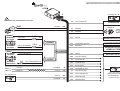
4600 CAN/PLIP
INSTALLATION MANUAL
Summary
1. KIT CONTENTS ............................................................................................................................................................3
2. INTRODUCTION & INSTALLATION METHODOLOGY (how to access to the vehicle specific technical documents,
Data Linker tool, Antares software, how to define the installation solution).......................................................................3
3. SYSTEM’S CONFIGURATION......................................................................................................................................4
4. HOW TO PREPARE PIN CODE CARD ........................................................................................................................5
5. INSTALLATION PROCEDURE (system’s component locations, electrical connections) ..............................................5
6. ACTIVE FUNCTIONALITIES (descriptions) ..................................................................................................................8
- ELECTRIC DIAGRAMS
7. PROGRAMMABLE FUNCTIONS (see the “Functions programming tables” manual) .........................................17
8. HOW TO PROGRAM FUNCTIONALITIES, COBRA REMOTE CONTROLS AND DRIVER CARDS SELF
LEARNING PROCEDURE (see ‘PAGE 1’ and ‘PAGE 2’ of the “Functions programming tables” manual) ............17
9. FUNCTIONAL TEST....................................................................................................................................................18
10. CAN INDEX MANUAL SELECTION ..........................................................................................................................18
11. SELF LEARNING PROCEDURE REQUIRED TO REPLACE THE MAIN UNIT OR THE WIRELESS SIREN
REPLACEMENT..............................................................................................................................................................18
12. DOCUMENTS HANDOVER ......................................................................................................................................19
13. TECHNICAL FEATURES ..........................................................................................................................................19
14. UK MARKET..............................................................................................................................................................19
2
INSTALLATION MANUAL 4600 CAN/PLIP
1. - KIT CONTENTS.
The following are the main parts supplied in the kit:
- Main alarm unit.
- Remote controls and/or Driver Card (optional).
- Wireless back-up battery siren or wired siren, loudspeaker.
- Main unit universal wiring harness.
- Siren wiring harness.
- Siren bracket.
- Ultrasonic sensors.
- Installation accessories.
- LED / control button.
- Quick reference user manual.
- Pin Code card.
2. - INTRODUCTION.
The main unit of this system is equipped with an on board CAN interface (Controller Area Network) that allows the data
reading from the vehicle CAN network. In can also be installed configured as PLIP, with this solution the unit is not connected
to the CAN network, but to the central door locking motors, to the door locking switches and/or to the direction lights.
It can be armed/disarmed by the vehicle original remote control, with the Cobra one or with the Driver Card (optional).
This manual contains all information required to fit the system on 12V battery vehicles with the negative pole connected
to the vehicle body.
HOW TO ACCESS TO THE VEHICLE SPECIFIC TECHNICAL DOCUMENTS, DATA LINKER TOOL, ANTARES
SOFTWARE.
Access to the web site www.cobra-at.com > Installer area and register yourself to be allowed to download the technical
documentation.
Data Linker programming tool and the software “Antares” are required to customize the product for the destination vehicle.
Data Linker is composed by a USB interface module, a 12V DC power supply, a CD containing the software “Antares” and the
required instructions. Product specific wiring harness are also supplied to connect the USB module to the product main unit.
Antares allows to configure/customize and to program the CAN/PLIP software for the destination vehicle using your computer.
HOW TO DEFINE THE INSTALLATION SOLUTION.
Access to the web site www.cobra-at.com > Login > user ID > password > access > professional area and, clicking on
the menu, supply all the requested destination vehicle information (in the example a VW Polo, year 2011) as the information
of the product to install, in this case the 4600 range.
VEHICLE TYPE.
Auto - Car
PRODUCT TYPE.
Antifurti auto - Car alarms
BRAND LIST.
Volkswagen
MODEL LIST.
Polo
3
INSTALLATION MANUAL 4600 CAN/PLIP
The list on the right side of the screen shows the product families. Clicking on the link you will get the full application list
available for the destination vehicle for the product family selected. Check at first if there is a CAN application available, it
offers the best compromise amoung functionalities offered/fitting time.
If no one CAN product installation proposal is available, make the same research clicking on “PLIP alarm” range AK4600
– 4400 Plip.
If there is an installation solution clicking on the vehicle model you can download the vehicle specific installation sheet.
If no one CAN and no one Plip installation proposal is available, choose again the vehicle type then, as “Product type” select
“Application manuals”. The list on the right side of the screen shows the application manuals available, click on “Application
manuals” to get the application manual list, then download the installation manual of the 4600 for the Plip configuration.
3. - SYSTEM’S CONFIGURATION.
Be sure to have connected all Data Linker components and to have power supplied the system.
Run Antares.
As soon as Antares is starting, it automatically checks - if the computer is connected to internet - if the installed version is
the most updated one and, if not, it proposes its update.
We recommend to download all times the last update.
Proceed as follow:
A.
Select the language.
B.
Select “alarm and modules”.
C.
Select product “4600 “ as “1 wire” or “2 wire”.
D.
Select the procedure “firmware update”.
E.
Click on “proceed”.
F.
Select the vehicle brand.
G.
Select the vehicle model.
H.
Select the vehicle model year.
I.
Click on “proceed”.
L.
Confirm and continue.
M.
Wait until the programming confirmation window appears.
Additional software installation and tool usage details are available on the specific manual supplied in the Data Linker kit
or in the Cobra web site, professional area, Application manuals.
4
INSTALLATION MANUAL 4600 CAN/PLIP
4. - HOW TO PREPARE THE PIN CODE CARD.
www.cobra-at.com
Remove the separate PIN Code label from the back of the system main unit and place onto the supplied PIN Code Card.
PIN
CODE
1122
4C4415A2A
S/N 0003 050524
PERSONAL
IDENTIFICATION
CODE
PIN
CODE
1122
5. - INSTALLATION PROCEDURE.
System’s component positioning.
As much as the components of the system will be placed in secure and difficult to access positions as higher the protection
level will be.
WARNING: each element must be positioned so that it does not interfere with moving parts.
Alarm unit.
It must be fitted inside the vehicle far away from heating sources, paying attention to keep the main connector oriented down.
Siren.
It can be installed in the engine bay as inside the vehicle far away from heating sources paying attention to keep the
main connector oriented down.
Ultrasonic volumetric sensor.
The ultrasonic transducers must be fixed to the top of the A pillars pointed towards the rear window or to the top of the
C pillars pointed towards the windscreen. Their orientation should be as much as possible parallel to the side windows.
Emergency LED/control button
It must be fitted on the dashboard with its LED in a in sight position. The pushbutton should be easily accessible by the
driver.
Bonnet pushbutton.
The installation of the supplied pushbutton is required if the vehicle is not yet equipped with the original one. The specific
vehicle CAN/PLIP installation sheet supplies this info.
Antennas.
The RF antennas positioning (for both the main unit and the siren) is crucial for a proper system’s performance. They must
not be cut, wrapped, connected to any other cables or to the vehicle body and they must be kept separate from the main
wiring harness and as far as possible from metallic parts.
5
INSTALLATION MANUAL 4600 CAN/PLIP
Electrical connections.
WARNING: to prevent damage to the vehicle electrical system during installation, we recommend to
disconnect the battery negative cable and to reconnect it only after installation is completed. If the battery
is not disconnected, to avoid the possible generation of errors by the original central units of the vehicle, it
is necessary to pay attention during the connections and the use of the installation tools.
Pay attention when joining two or more wires. Avoid to make “quick connections” that do not ensure a good quality.
Also make sure that the wires of the Cobra 4600 are routed so that they follow the original wiring of the vehicle to which
they should be joined with the raps.
The addition of fuse is required as specified in the main connection diagram.
26 ways connector J pin-out for CAN configurations
J-1 and J-2 Engine crank inhibition: to get the maximum security level to the system connect the two wires as shown in the
electrical diagrams to prevent the engine starter running. During the cranking phase, measure the value of the current in the circuit that
has been interrupt, to make sure that it does not exceed the technical specifications of the product. Install an additional relay if required.
J-3 Logic blinker output: make the connection if required by the specific vehicle CAN installation sheet.
J-4 Power blinker output: make the connection if required by the specific vehicle CAN installation sheet.
J-5 Logic blinker feedback input or power blinker output: make the connection if required by the specific vehicle
CAN installation sheet.
J-6 Analogic input: to be connected to a vehicle device (ex. passenger compartment fan heater) to reduce the US sensitivity
(step 7.12) or to be connected to a push-button for the driver recognition (step 7.22). If the wire connection of this input is required
in the CAN application, it can not be used for the functions as in step 7.12 and 7.22.
J-7 Analogic input: make the connection if required by the specific vehicle CAN installation sheet.
J-8 Cobra bus: communication line for the connection of compatible Cobra sirens and sensors.
J-9 and J-10 CAN H/L: to connect as shown in the specific vehicle CAN installation sheet.
J-11 Pager negative output: low power control signal for triggering a pager device or a telematic one. Active low during alarm time.
J-12 CDL unlock negative output: low power control signal to unlock central door locking. Activated by the Cobra remote
control (optional) - (see electrical diagram F).
J-13 Analogic input: make the connection if required by the specific vehicle CAN installation sheet.
J-14 12V connection (+30): the positive supply must be connected to a vehicle positive connection point upstream of the fuse
box. Fit a 15A fuse as close as possible to the connection point.
J-15 GND connection: the ground must be connected to a factory earth point or directly to the negative pole of the battery.
J-16 Negative output for modules: active when the system is armed. To be used for the connection of compatible Cobra
modules.
J-17 Horn/loudspeaker negative output: to program in line with the connected device. See electric diagrams and
functionalities programming tables. The output set automatically as per selected device, for horn choose also fix or intermittent.
J-18 +15/54 connection: if the signal is not detected from the CAN network , connect this input to the ignition key on, checking
that the wire is permanently fed during the crancking phase and while the engine is running. Fit a 3A fuse as close as possible to
the vehicle connection point.
J-19 Analogic input: make the connection if required by the specific vehicle CAN installation sheet.
J-20 Analogic input: make the connection if required by the specific vehicle CAN installation sheet.
J-21 Negative input to enter in programming procedure/to connect bonnet pushbutton: if connected to
ground the system will enter in the programming procedure for all applications not able to detect the original bonnet pushbutton. If the
siren is a wireless one this input must not be used for the bonnet pushbutton connections. For wired siren or loudspeaker this input
must be used for the connection of the bonnet pushbutton as indicated in the specific vehicle CAN installation sheet.
6
INSTALLATION MANUAL 4600 CAN/PLIP
J-22 Analogic input: make the connection if required by the specific vehicle CAN installation sheet.
J-23 Negative input for additional modules: to be used as a triggering input for the connection of compatible Cobra modules.
J-24 Analogic output: to be used for the function described in step 7.17 or 7.20.
J-25 CDL lock negative output: low power control signal to lock central door locking. Activated by the Cobra remote control
(optional) - (see electrical diagram F).
J-26 Analogic input: make the connection if required by the specific vehicle CAN installation sheet.
26 ways connector J pin-out for PLIP configurations
J-1 and J-2 Engine crank inhibition: to get the maximum security level to the system connect the two wires as shown in the
electrical diagrams to prevent the engine starter running. During the cranking phase, measure the value of the current in the circuit that
has been interrupt, to make sure that it does not exceed the technical specifications of the product. Install an additional relay if required.
J-3 Logic blinker output: make the connection if required by the specific vehicle PLIP installation sheet.
J-4 Power blinker output: make the connection if required by the specific vehicle PLIP installation sheet.
J-5 Logic blinker feedback input or power blinker output: make the connection if required by the specific vehicle
PLIP installation sheet.
J-6 Blinker inhibition positive input: to connect as indicated in the specific vehicle PLIP installation sheet or in the product
installation guide for PLIP applications available on the web under Application manuals.
J-7 Negative input for CDL opening switch signal: to connect as indicated in the specific vehicle PLIP installation sheet
or in the product installation guide for PLIP applications available on the web under Application manuals.
J-8 Cobra BUS: communication line for the connection of compatible Cobra sirens and sensors.
J-9 and J-10 Do not connect.
J-11 Pager negative output: low power control signal for triggering a pager device or a telematic one. Active low during alarm time.
J-12 CDL unlock negative output: low power control signal to unlock central door locking. Activated by the Cobra remote
control (optional) - (see electrical diagram F).
J-13 Positive input for CDL motor opening signal: to connect as indicated in the specific vehicle PLIP installation sheet
or in the product installation guide for PLIP applications available on the web under Application manuals.
J-14 12V connection (+30): the positive supply must be connected to a vehicle positive connection point upstream of the fuse
box. Fit a 15A fuse as close as possible to the connection point.
J-15 GND connection: the ground must be connected to a factory earth point or directly to the negative pole of the battery.
J-16 Negative output for modules: active when the system is armed. To be used for the connection of compatible Cobra
modules.
J-17 Horn/loudspeaker negative output: to program in line with the connected device. See electric diagrams and
functionalities programming tables. The output set automatically as per selected device, for horn choose also fix or intermittent.
J-18 +15/54 connection: to be connected to a ignition key ON positive signal. The positive signal must be feeded while starting
the vehicle and when the engine is ON.
J-19 Negative input for CDL closing switch signal: to connect as indicated in the specific vehicle PLIP installation
sheet or in the product installation guide for PLIP applications available on the web under Application manuals.
J-20 Positive perimetric input: to be connected to the vehicle roof lamp. The input is 7 s delayed after the system arming.
J-21 Negative input to enter in programming procedure/to connect bonnet pushbutton: if connected to
ground the system will enter in the programming procedure for all applications not able to detect the original bonnet pushbutton. If the
siren is a wireless one this input must not be used for the bonnet pushbutton connections. For wired siren or loudspeaker this input
must be used for the connection of the bonnet pushbutton as indicated in the specific vehicle PLIP installation sheet.
7
INSTALLATION MANUAL 4600 CAN/PLIP
J-22 Positive perimetric input: to be connected to the vehicle roof lamp. The input is 7 s delayed after the system arming.
J-23 Negative input for additional modules: to be used as a triggering input for the connection of compatible Cobra modules.
J-24 Analogic output: to be used for the function described in step 7.17 or 7.20.
J-25 CDL lock negative output: low power control signal to lock central door locking. Activated by the Cobra remote control
(optional) - (see electrical diagram F).
J-26 Positive input for CDL motor closing signal: to connect as indicated in the specific vehicle PLIP installation sheet
or in the product installation guide for PLIP applications available on the web under Application manuals.
MAKE CONNECTIONS AS FOR ELECTRIC DIAGRAMS
6. - ACTIVE FUNCTIONALITIES.
6.1 - Interior protection with ultrasonic volumetric sensor.
The system protects the vehicle interior with a volumetric ultrasonic sensor. Any attempt to get into the vehicle will be
detected and the alarm will trigger.
6.2 - Perimetric protection with door open warning diagnostic.
The alarm will trigger by opening any door, boot and bonnet. Should you have left any door opened while arming, the system
will signal it by 3 flashes of the direction lights and 3 audible signals (5 audible signals if the arming/disarming audible
signals function has been activated).
6.3 - Cable cutting protection (only for systems with back-up battery siren).
The alarm will trigger if the system is not power supplied (cutting of cables - battery disconnection) signalling the sabotage.
6.4 - Engine crank inhibition.
As soon as the system is armed the engine cranking is not possible anymore.
6.5 - Arming the system with the volumetric ultrasonic protection disabled.
This function allows to arm the system leaving temporarily disconnected the interior volumetric protection. The protection
must be disabled any time you leave somebody or an animal in the vehicle. If you want to leave any window opened also
disable the protection to avoid false alarms. All other protections remain active.
To disable the volumetric protection proceed as follow:
switch the engine off being sure that the ignition switch has been turned to the OFF position. Within 5 s press the emergency
panel pushbutton and keep it pressed until it will flash once to confirm only the volumetric protection has been disabled.
By keeping the pushbutton pressed the system will confirm with two flashes that only the additional sensor input has been
disabled, with three flashes for both of them disabled. The selected protection will remain disabled until the system will be
disarmed. It will be automatically restored at the next arming.
Note: on some vehicles the system automatically disables the volumetric protection if any windows is left opened.
6.6 - Emergency panel LED.
The LED main scope is to show the system arming and disarming conditions. When the system is armed the LED gets
ON and remains illuminated until the 25 s arming period has elapsed. After that it starts blinking. It goes OFF as soon as
the system is disarmed.
8
INSTALLATION MANUAL 4600 CAN/PLIP
4600 Art. (NO WIRELESS SIREN)
LED
J
See diagram "H"
THE FUSES IN THE DIAGRAM ARE NOT SUPPLIED
GND
15 A
POWER
YELLOW-WHITE
3A
HAZARD
BLINKER
FEEDBACK
CAN - H
J-4
7,5 A J-5
YELLOW-GREEN
LOGIC
BLINKER
OUTPUT
CAN - L
7,5 A
YELLOW
BLINKER
OUTPUT
POWER
BLINKER
J-3
LOGIC
YELLOW-GREEN J-5
VIOLET
ORANGE
J9
ORANGE
VIOLET
J10
See diagram 'F'
YELLOW-BLUE
J1
GREEN
J2
GREEN
J17
WHITE
J11
ORANGE-WHITE
J16
BROWN
J23
GREY
J24
VIOLET-WHITE
BLACK J-15
RED J-14
BLINKER
OUTPUT
J8
VIOLET
J25
ORANGE
J12
J6
PINK-WHITE
J20
PINK-BLACK
J22
BLUE-PINK
J19
ORANGE-BLACK
J7
VIOLET-BLACK
J26
YELLOW-BLACK
J13
GREY-BLACK
J18
GREEN-RED
COBRA BUS
STARTER +50
max 20A (1 sec.)
6A cont.
SIREN HORN OUTPUT
PAGER OUTPUT
NEGATIVE OUTPUT
ARMED SYSTEM
SENSORS INPUT
See the vehicle
fitting instructions or
the CAN/PLIP J 26
connector pin out
4600 Art. (WIRELESS SIREN)
LED
THE FUSES IN THE DIAGRAM ARE NOT SUPPLIED
POWER
BLINKER
OUTPUT
BLINKER
OUTPUT
LOGIC
BLINKER
OUTPUT
HAZARD
BLINKER
FEEDBACK
15 A
7,5 A
YELLOW
YELLOW-GREEN
YELLOW-WHITE
3A
GND
7,5 A
J
J-4
J21
POWER
See paragraph 11
J8
YELLOW-BLUE
J9
ORANGE
VIOLET
J10
VIOLET
ORANGE
J1
GREEN
J2
GREEN
J17
WHITE
J7
J11
ORANGE-WHITE
YELLOW-BLACK
J26
J16
BROWN
GREY-BLACK
J13
GREEN-RED
J18
BLUE-PINK
J22
J25
VIOLET
PINK-BLACK
J20
J12
ORANGE
PINK-WHITE
J6
J23
GREY
J-5
BLINKER
J-3
COBRA BUS
CAN - L
CAN - H
LOGIC
YELLOW-GREEN J-5
BLACK
J-15
RED
J-14
ORANGE-BLACK
VIOLET-BLACK
See the vehicle
fitting instructions or
the CAN/PLIP J 26
connector pin out
BLUE
VIOLET-WHITE
STARTER +50
max 20A (1 sec.)
6A cont.
SIREN HORN OUTPUT
J19
J24
PAGER OUTPUT
NEGATIVE OUTPUT
ARMED SYSTEM
See diagram "F"
SENSORS INPUT
BONNET PUSH-BUTTON
NO WIRELESS SIREN CONNECTIONS
H
J
BLACK
BLUE
YELLOW-BLUE
YELLOW-BLUE
RED
3A
See the
vechicle
fitting
instructions
J-21
J-8
+30
1
2
Ø 10 mm
14 mm
BLACK
1
2
Ø 10 mm
Ø 2 mm
BLACK
LED PANEL
WIRELESS SIREN CONNECTIONS
LED
See the
vechicle
fitting
instructions
2
1
1
Antenna
2
BLUE
RED
BLACK
3 A +30
Ø 10 mm
A
B
U.S.
C
U.S.
D
WHITE wire J 17
-/+
WHITE wire J 17
+30
PA
SS
PA
SS
TX
TX
TX
LE
D
TX
LE
D
87
BLACK
RX
RX
30 86 85
Y
RX
RX
Y
-/+
RED (TX)
Antenna
Install the jumper wire (see the catalogue)
between the Ultrasound TX and RX, if you don't
use the volumetric sensor.
+30
E
WHITE wire J 17
WHITE
(RX)
BLACK
-
3A
Original relay controlled by a negative signal.
Vehicle horn connection with negative control
signal to the original relay.
U.S. sensors, led
panel and antenna
connections.
F
G
15A
OK
1N4004
87
- +
Original
system
J12
ORANGE
J25
VIOLET
30 86 85
Additional
relay
Vehicle horn connection with additional relay.
Low power outputs for vehicles with
negative CDL control signals.
1
2
3
6.7 - Alarms memory.
If the system has gone off (alarm on) during the arming time it will warn you with 3 flashes of the direction lights and 3 audible
signals (5 audible signals if the arming/disarming audible signals function has been activated). It also stores in its memory
the reason of the occurred alarm and shows it on the emergency panel LED. Count the number of flashes and check the
corresponding alarm reason on the table. By turning the key ON the memory will be deleted.
LED NUMBER OF
FLASHES
ALARM ROOT
CAUSE
1 flash
Door opening detection.
2 flashes
Ultrasonic volumetric detection.
3 flashes
Bonnet opening detection.
4 flashes
Ignition key ON detection.
5 flashes
Boot opening detection.
6 flashes
Door opening detection.
7 flashes
Additional sensors.
8 flashes
Siren cable cutting - Cobra Bus.
9 flashes
Not used.
10 flashes
Not used.
11 flashes
Immobilizer 1 module connected to the Cobra Bus.
12 flashes
Immobilizer 2 module connected to the Cobra Bus.
13 flashes
Keyboard module connected to the Cobra Bus.
14 flashes
Not used.
6.8 - Emergency disarming.
If the vehicle original remote control get lost or if it doesn’t work, open the door with the mechanical key and turn the ignition
key ON. If the system doesn’t disarm automatically follow the emergency procedure described in the user manual.
6.9 - Alarm condition.
When the system goes off (alarm ON) the siren sounds and the direction lights flash for 28 s.
7. - PROGRAMMABLE FUNCTIONS.
(see the “FUNCTIONS PROGRAMMING TABLES” manual).
8 - HOW TO PROGRAM FUNCTIONALITIES, COBRA REMOTE CONTROLS AND DRIVER CARDS SELF
LEARNING PROCEDURE.
IMPORTANT: (only for PLIP applications and just after the power supply connection or when the battery has been
disconnected and reconnected). Before entering in the functions programming procedure, arm the system, wait
until the emergency panel LED starts flashing, then disarm the system. From now on it will be possible to performe
the programming procedure.
(see ‘PAGE 1’ and ‘PAGE 2’ of the “FUNCTIONS PROGRAMMING TABLES” manual).
17
INSTALLATION MANUAL 4600 CAN/PLIP
9. - FUNCTIONAL TEST.
During the first 25 s after the system has been armed all protection functionalities can be tested without triggering an alarm.
Make the following tests during the 28 s inhibition time with the system armed:
open then close one by one all doors and boot - Check if the system is confirming with three audible signal, each door
opening detection.
Check the proper functionality of the volumetric ultrasonic sensor - Make movements from the back seat, their detection
will be confirmed by a LED flashing.
Note: don’t check the proper functionality of the volumetric ultrasonic sensor with the windows opened as many CAN applications
are automatically excluding this protection when the windows are left opened.
Open the bonnet then lock the vehicle with the remote control - While arming the system will indicate the bonnet opening
with 3 flashes of the direction lights and correspondingly with audible signals.This test is applicable only if the signal is detected
from the CAN network or for systems wired siren.
Try to start the engine - If the engine cranking wires have been connected the engine will not start. Warning: on some vehicle
by turning the ignition key ON the system will disarm (TRANSPONDER detection).
Check if the PIN emergency Code works properly - By correctly entering the PIN code the system disarms.
10. - CAN / PLIP INDEX MANUAL SELECTION.
The technical support could ask you to manually select a different CAN / PLIP index of the brand which has been loaded in
the main unit. To select a different CAN / PLIP application (CAN INDEX) proceed as follows:
as soon as the system is powered - in the disarming state - the emergency panel LED flashes quickly for 5 s, during this time
frame keep pressed the emergency panel pushbutton until it will go off then release it. The LED starts flashing slowly a number
of time corresponding to the already set index (example 3 flashes for index 3).
While the LED is flashing slowly, press briefly the button of the emergency panel to switch to the next index; each time you press
the button the index increases and so on. By pressing again when the last index has been selected the system will switch back
to the first one of the list. Select the correct CAN / PLIP index, then wait for the LED off to confirm the current index selection.
Note1: the same CAN index can be used for many vehicle models, check the CAN INDEX table available on the web.
Note2: there are four PLIP index available, check the vehicle specific PLIP installation sheet or the PLIP application manual
available on the web in the “Application Manuals” section.
11. - SELF LEARNING PROCEDURE REQUIRED TO REPLACE THE MAIN UNIT OR THE WIRELESS
SIREN REPLACEMENT.
The siren supplied in the kit is delivered already programmed to the main unit. Should you have the need to replace the siren
or the main unit it is required to perform the self learning procedure as follows:
IMPORTANT: don’t perform the procedure on two different vehicles parked closed each other. Their sirens could be memorized
in one main unit only.
A.
B.
C.
D.
E.
F.
G.
Power the main unit by connecting the 26 ways connector.
Connect the main unit blue wire to GND (only when a wireless siren is fitted).
Open the bonnet.
Connect the siren blue wire to GND (if not already grounded through the additional bonnet pushbutton).
Disconnect the siren 6 ways connector, then plug it again.
Within 60 s turn the ignition key ON, an audible signal confirms that the siren has been stored in the system.
Turn the ignition key OFF and disconnect the BLU wires of the main unit and of the siren from GND (if grounded through
the additional pushbutton simply open the bonnet).
Check the system functionality arming the system and triggering the alarm to check the proper sounding of the siren.
18
INSTALLATION MANUAL 4600 CAN/PLIP
12. - DOCUMENTS HANDOVER.
Be sure the user user ‘quick reference’ and the PIN code card is placed in the glove compartment and carry out a full
functionality demonstration to the customer.
13. - SYSTEM TECHNICAL SPECIFICATIONS.
The manufacturer shall not be liable for any faults or malfunctions in the anti-theft device and/or in the electrical system of
the vehicle due to incorrect installation and/or to failure to comply with the indicated technical specifications. The system
must only be considered as a deterrent agaist theft attempts.
TECHNICAL SPECIFICATIONS 4600
Rated supply voltage
Operating voltage
+8 V ÷ +16 V DC
Current consumption (central unit, LED and siren) disarmed
8 mA
Current consumption (central unit, LED and siren) armed
12 mA
Central unit operating temperature
- 40 °C + 85 °C
Siren operating temperature
- 40 °C + 85 °C
Self power supply
Lithium Battery 6 V 1300 mAh
Loudspeaker sound pressure level
>115 dB @ 1m
Siren sound pressure level
>114 dB @ 1m
- Central dimensions
91x69x35 mm
- Siren dimensions
113x79x45 mm
Trasmitter battery / Cobra Driver Card
14. - FOR
+12 V DC
UK
Lithium Battery 3 V CR2032
MARKET ONLY
Category 1,2 or 2-1 systems permanently installed as aftermarket equipment by import or distribution centres, vehicle
dealers, or by Independent Installers, shall be installed by companies and technicians who are trained, qualified, industry
recognised professional installers.
Thatcham recommends to its insurer members that the installations of certified products within the aftermarket are registered
with an independent installation registration system which can be accessed by insurance companies. Thatcham administer
the Thatcham Recognised Installer scheme, on behalf of the British motor insurance industry, providing independent
registration of installations to vehicle owners. Details of the Thatcham Recognised Installer scheme can be found at www.
thatcham.org/tri/home. To ensure consumers insurance cover is not adversely effected it is highly recommended that all
installations are carried out by Thatcham recognised installers and that all installs are registered providing the vehicle
owner with a Thatcham recognition of installation for presentation to insurers.
19
INSTALLATION MANUAL 4600 CAN/PLIP
Cobra Automotive Technologies
via Astico 41 - 21100 VARESE - ITALY
www.cobra-at.com
06DE3325C - 06/12