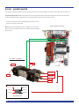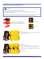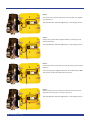
1
Manufactured by
Holland Marine Parts B.V.
Installation manual
& user guide
Jet Thruster Single, Combi & Vertical
www.jetthruster.com
Jet Thrusters:
JT-30 / JT-50 / JT-70 / JT-90
All our products are manufactured according to CE regulations.
We keep the rights to change descriptions, graphs or statements,
which are required for technical development of our Jet Thruster systems.
2
Holland Marine Parts
Table of Contents
Preface
4
Warranty Provisions
5
Safety
6
User Guide Jet Thruster Holland Marine Parts
7
Troubleshooting
8
Winterising
9
Jet Thruster pump units
10
Technical Specifications
13
Installing the Jet Thruster Single
25
Nozzle positions and installation options
31
Installing the Jet Thruster vertical
36
IP protective cover for gasoline engine areas
39
Electrical Installation Jet Thruster Single
43
Installing the electrical air valve
45
Installing the Jet Thruster Combi
51
Electrical Installation Jet Thruster Combi
53
Jet Thrusters
Appendix A:
Electrical diagram
59
Appendix B:
Exploded view
60
Appendix C:
Electrical installation
62
Series parallel switch
64
Connecting the series-parallel circuit
65
Test rapport / information about installation
69
Notes
70
Project info
71
Holland Marine Parts
3
Preface:
Holland Marine Parts keeps you moving!
Thank you very much for your purchase of the Jet Thruster.
This electric system greatly simplifies the manoeuvring of your vessel!
The extensive development process of the Jet Thruster guarantees a complete and innovative system that will make operating
your boat a breeze!
The Jet Thruster systems by Holland Marine Parts are made of quality materials. For the correct and safe operation of the Jet
Thruster you have purchased, we recommend having it professionally installed. A professional installation
taking into account the recommendations in this installation / user manual guarantees a well-working system.
This installation manual has been prepared with the utmost care. If you experience installation trouble please contact your Jet
Thruster dealer. We point out that some vessels require adjustments to assure their integrity. For all your questions about this
please contact your shipbuilder.
Holland Marine Parts
4
Holland Marine Parts
Warranty provisions
On all its newly manufactured products Holland Marine Parts provides quality assurance regarding their proper operation,
both with regard to the material and the work done, including latent defects, for a period of 24 months after the invoice
date to the first receiver.
In case of defects in material and/or defects caused by inadequate work done, as covered under warranty by Holland Marine Parts, the relevant part or the whole device will be either repaired or replaced at the discretion Holland Marine Parts,
free of charge.
The warranty periods specified in the first paragraph are not extended by the implementation of repairs under warranty.
Any costs associated with travel, transportation and installation and/or disassembly with regard to repairs covered under
warranty will be borne by the owner of that device.
Damage to the product caused by improper installation, by intentional or unintentional misuse, lack of maintenance,
normal wear and/or repair by third parties without the written permission of Holland Marine Parts are not covered by
warranty.
Holland Marine Parts shall under no circumstances be liable for any consequential damages of any nature whatsoever or
howsoever caused by the part or the whole product covered by warranty by Holland Marine Parts.
Please note: Exclusion of warranty: The pump head of the pump unit and the gaskets on the 3-way valve are tested to be
waterproof. If they are opened/removed/damaged this will void all liability towards Holland Marine Parts in the occurrence of damage as a result of these actions.
In this manual the installation of the JT-30, JT-50, JT-70 and JT-90 in Single and Combi setup is explained.
Choose the installation procedure that applies to the system you have purchased.
Holland Marine Parts
5
Safety: read this prior to installation or operation.
This installation manual provides advice about the complete installation of the Jet Thruster.
Remarks about safety are accompanied by this symbol.
In rare conditions it might be possible that the pump unit of the Jet Thruster does not prime. If you notice a high rpm from
the pump unit and no thrust force, do not attempt to prime the pump unit by continuous activating the system. In this situation the Electrical air valve from Holland Marine Parts should be installed to release the air from the pump head. This will
prime the pump. Do not run the pump unit without the presence of water!
Follow all instructions in this manual. All users of the system must be aware of the mandatory safety regulations
as explained in this manual:
- Preferably leave installation and maintenance of the system to a dealer authorised by Holland Marine Parts.
- Use appropriate tools for the installation and maintenance of the Jet Thruster.
- Provide the Jet Thruster seperate battery(s). Place the battery(s) as close to the pump unit of the Jet Thruster as possible.
- Always use a Holland Marine Parts control panel.
- Do not touch any moving parts of an active system.
- Parts such as the DC pump motor may become hot: do not touch them and do not cover them under any circumstances.
- Avoid having flammable products near the DC pump motor.
- Do not conduct any inspection or maintenance of the system when it is active.
- Do not close any valves of an active system.
- The system is located beneath the water line. Do not remove any parts of the system before all valves have been closed.
- Close all valves when you are not aboard.
- Leave system maintenance to specialists.
- Disconnect the battery cables when conducting maintenance and in the event of long-term absence
(e.g. when the vessel is not being used in winter).
- The hoses are under pressure in an active system: high-pressure hoses are to be attached to the vessel to prevent
movement along e.g. sharp edges.
- Protect the high-pressure hoses from heat / penetration / sunlight / chemicals.
- Avoid physical contact with the water inlet when the system is active.
- Avoid physical contact (swimmers!) with the nozzles and the water expelled by an active system.
- Danger! Protect pump unit and 3-way valve from petrol fumes.
Provide sufficient ventilation. Ignition proof covers are available.
6
Holland Marine Parts
User Guide Jet Thruster Holland Marine Parts
JT-30
JT-50
JT-70
JT-90
Your vessel is equipped with a Holland Marine Parts electric Jet Thruster. For the safe and correct operation of this system
Holland Marine Parts recommends every user to carefully study this operating guide. Familiarise yourself with the system by
trying it out in various weather conditions. The windage and draught as well as the weight of your vessel are factors contributing to how well the system operates.
Warnings:
•The Jet Thruster is not a replacement of the main controls but assists with the execution of difficult manoeuvres.
•Familiarise yourself with the way your vessel responds to your operation of the system.
•The electric motor produces heat. The thermal protection limits continuous operation to about 4 minutes.
•The water inlet is located on the bottom of your vessel. Inquire about the exact location of the water inlet grating.
•Prevent the system from sucking in large amounts of sand and dirt. Do not activate it when you have less than 30cm (12”)
of ground clearance.
•The nozzles of the Jet Thruster are located beneath the water line. Do not activate the system and do not operate the Jet Thruster when there are people, animals or vulnerable items in the vicinity of your vessel and the inlet and orifices.
•Close all the valves when you are not aboard. Inquire about the local regulations in ports with regard to closing the valves.
Operation:
You operate the Jet Thruster by activating the system on the front plate of the control panel by pressing the button (A). This
switch is illuminated in blue when the system is active.
Operate the Jet Thruster by moving the joystick(s) (B) left or right, moving the bow or stern to port or starboard, respectively.
When equipped with push buttons, the same procedure applies, the push buttons being illuminated in green or red light.
B
A
Duration of activation:
Prevent the use of many short pulses. Instead, move your vessel by means of pulses that last a few seconds. The efficiency of
the system is determined in part by the battery capacity present. The overheating protection will activate when the system is
active for an extended period of time. After the engine has cooled sufficiently this protection is removed. The cooling time is
determined in part by the ambient temperature.
Jet Thruster Combi:
The control panel is equipped with two joysticks or push buttons. You can move sideways by operating both push buttons for
bow and stern at the same time. You can manoeuvre the vessel around the centre of rotation by manoeuvring the bow to
port and the stern to starboard, or the other way around.
Holland Marine Parts
7
Troubleshooting
If the system is not functioning:
Problem
1.1 System is not working (power indicator off)
Cause
Solution
Joystick not receiving power
Press the switch
1.2
System is not working
(power indicator off)
Joystick not receiving power
Check fuse 15A
behind joystick
2.1
System is not working (power indicator on) Battery dead or main fuse broken
Check / replace fuse
2.2
System is not working
(power indicator on)
Damaged relay
Contact your dealer
Overheating protection activated
Leave engine to cool 3.1 Engine running, no activity
Valves closed
Check whether or not
valves are closed
3.2 Engine running, no activity Engine does not draw water
Place pump unit inlet
below water line
3.3
Engine running, no activity
Polluted system (shallow water)
Run engine in deep water
until clean
3.4
Engine running, no activity Damaged impeller
Contact your dealer
4.1 Engine running, no activity System operates inverted Cabling fault Exchange A
and B on the pump unit
4.2
System is not efficient enough
Low battery voltage
Charge batteries,
see electrical installation page 22
Check actual voltage at meter.
4.3 Not enough power
Series-parallel does not activate,
Check connections
(JT-50 24V, JT-70 and JT-90)
system runs at 12V
series-parallel switch
8
Holland Marine Parts
Winterising:
2” / 51 mm
Preferably have the system winterised by a specialist.
Please note: Frost can do a lot of damage if you fail to drain the system.
Use a compressor to remove the water present in the system
by means of air pressure.
Please note: Excessive pressure may damage the system. Check the operating
pressure you use to pressurise the system with.
This operating pressure must not exceed 2 bar (30 psi).
(A)
3” / 76 mm
Step 1: Disconnect the + cable from the battery.
Step 2: Close all valves.
Step 3: Remove the blind plug or air valve in the outlet (A) of the pumpunit.
(A)
Step 4: Screw a compressed-air nipple in the outlet.
Step 5: Pressurise the system. MAX 2 BAR (30 psi)!
3” / 76 mm
Step 6: Open the ball valves one by one and close them the instant you hear
a bubbling sound. Repeat this procedure for every ball valve.
Step 7: Remove the compressed-air nipple.
(A)
Step 8: Replace the blind plug or airvalve.
In addition you can drain the pumphouse, therefore remove draining plug
for draining the pumphouse.
3” / 76 mm
(A)
JT-30 / JT-50
JT-70 / JT-90
Holland Marine Parts
9
Jet Thruster pump units
Note: Thread sizes of all Jet Thruster com-ponents in Whitworth
Pipe Thread DIN ISO 228 BSP (DIN 259) British Standard Pipe.
JT-30 66 thrust LBS 12V
JT-50 110 thrust LBS 24V
Force
Voltage DC
E-motor capacity kW
Current
Master fuse
Recommended battery capacity 12V
Battery cable +/Water inlet
Water outlet
Pressure hose diameter
Weight pump
30 Kgf
12V
3kW
376A
425A
1 x Optima Yellow Top 55Ah
1m -> 50mm2 / 3ft -> 1/0 AWG
1 x Ø 90 mm/3⅟₂”
Nozzle Ø 36mm/1,26”
2” / 51 mm
29kg/64LB
Force
Voltage DC
E-motor capacity kW
Current
Master fuse
Recommended battery capacity 12V
Battery cable +/Water inlet
Water outlet
Pressure hose diameter
Weight pump
50 Kgf
24V
6kW
380A
425A
2 x Optima Yellow Top 75Ah
1m -> 50mm2 / 3ft -> 1/0 AWG
1 x Ø 90 mm/3⅟₂”
Nozzle Ø 36mm/1,26”
2” / 51 mm
34 kg/75 LB
Pump unit
LxWxH: 442x425x330-340 mm
lxwxh: 17.4x16.73x13-13.38 inch
Pump unit
LxWxH: 495,5x425x330-360 mm
LxWxH: 19⅟₂x16.73x13-14.17 inch
3-Way valve
LxWxH: 240x160x189 mm
LxWxH: 9.44x6.29x7.44 inch
3-Way valve
LxWxH: 240x160x189 mm
LxWxH: 9.44x6.29x7.44 inch
JT-50 88 thrust LBS 12V
JT-90 198 thrust LBS 24V
Force
Voltage DC
E-motor capacity kW
Current
Master fuse
Recommended battery capacity 12V
Battery cable +/Water inlet
Water outlet
Pressure hose diameter
Weight pump
40 Kgf
12V
6kW
730A
850A
1 x Optima Yellow Top 75Ah
1m -> 70mm2 / 3ft -> 2/0 AWG
1 x Ø 90 mm/3⅟₂”
Nozzle Ø 36mm/1,26”
2” / 51 mm
36 kg/80 LB
Force
Voltage DC
E-motor capacity kW
Current
Master fuse
Recommended battery capacity 12V
Battery cable +/Water inlet
Water outlet
Pressure hose diameter
Weight pump
90 Kgf
24V
15,5kW
980A
1000A
4 x Optima Yellow Top 75Ah
1m -> 120mm2 / 3ft -> 4/0 AWG
1 x Ø 4”
Nozzle Ø 50mm
3” / 76 mm
49 kg/130 LB
Pump unit
LxWxH: 495,5x425x330-360 mm
LxWxH: 19⅟₂x16.73x13-14.17 inch
Pump unit
LxWxH: 675x381x365 mm
LxWxH: 26.57x15x14.37 inch
3-Way valve
LxWxH: 240x160x189 mm
LxWxH: 9.44x6.29x7.44 inch
3-Way valve
LxWxH: 280x235x230 mm
LxWxH: 11x9.25x9 inch
JT-70 154 thrust LBS 24V
Force
Voltage DC
E-motor capacity kW
Current
Master fuse
Recommended battery capacity 12V
Battery cable +/Water inlet
Water outlet
Pressure hose diameter
Weight pump
70 Kgf
24V
11kW
655A
710A (2x 355A)
2 x Optima Yellow Top 75Ah
1m -> 95mm2 / 3ft -> 3/0 AWG
1 x Ø 4”
Nozzle Ø 50mm
3” / 76 mm
43 kg/95 LB
Pump unit
LxWxH: 540x405x355 mm
LxWxH: 21.25x15.95x14 inch
3-Way valve
LxWxH: 280x235x230 mm
LxWxH: 11x9.25x9 inch
All prices ex. VAT
Holland Marine Parts
43
Holland Marine Parts
11
12
Holland Marine Parts
Ø 51mm / 2”
105mm / 4.13”
66mm / 2.6”
Technical Specifications JT-30
Pump head in position I
100x100mm / 3.94”x 3.94”
P-142-00: Straight pump outlet
Ø 51mm / 2”
100x180mm / 3.94”x 7.08”
P-122-00: 900 pump outlet
304 /12"
250 mm / 9.84”
90 mm / 2.54”
Inlet
2½”
3” BSP
80 mm / 3.14”
180 mm / 7.08”
2 options for hose connector
on pump outlet:
Water inlet assembly:
Connect with flexible hose to inlet on pump unit. Max. hose length 1 m / 3.3 ft
175 / 6.9"
160 / 6.3"
375 / 14.75"
312 / 12.3"
440 mm / 17.71”
146 / 5.75
240 / 9.45"
56 / 2.2"
78,69 / 3.1"
442 / 17.4"
125 / 12.92"
110 / 4.33"
11 / 0.43"
115 / 4.53"
Holland Marine Parts
13
100x100mm / 3.94”x 3.94”
P-142-00: Straight pump outlet
2 options for hose connector
on pump outlet:
105mm / 4.13”
Ø 51mm / 2”
66mm / 2.6”
Technical Specifications JT-30
Pump head in position II
Ø 51mm / 2”
100x180mm / 3.94”x 7.08”
P-122-00: 900 pump outlet
304 / 11.97"
250 mm / 9.84”
90 mm / 2.54”
Inlet
2½”
3” BSP
80 mm / 3.14”
180 mm / 7.08”
Water inlet assembly:
Connect with flexible hose to inlet on pump unit. Max. hose length 1 m / 3.3 ft
312 / 12.3"
140 / 15.5"
440 mm / 17.71”
175 / 6.9"
302,5 / 11.9"
146 / 5.75"
367 / 14.45"
240 / 9.45"
56 / 2.2"
14
Holland Marine Parts
125 / 4.92"
110 / 4.33"
11 / 0.43"
115 / 4.5"
367 / 14.45"
76 / 3.1"
442 / 17.4"
105mm / 4.13”
Ø 51mm / 2”
66mm / 2.6”
Technical Specifications JT-50
Pump head in position I
100x100mm / 3.94”x 3.94”
P-142-00: Straight pump outlet
Ø 51mm / 2”
100x180mm / 3.94”x 7.08”
P-122-00: 900 pump outlet
90 mm / 2.54”
80 mm / 3.14”
180 mm / 7.08”
2½”
3” BSP
250 mm / 9.84”
Water inlet assembly:
Connect with flexible hose to inlet on pump unit. Max. hose length 1 m / 3.3 ft
2 options for hose connector
on pump outlet:
440 mm / 17.71”
109,5 / 4.3"
240 / 9.4"
146 / 5.7"
304 / 12.0"
175 / 6.9"
239,5 / 9.4"
8 / 0.3"
375 / 14.8"
160 / 6.3"
11
/0
"
.43
110 / 4.3"
80 / 3.1"
349 / 13.7"
Inlet
115 / 4.5"
Holland Marine Parts
15
105mm / 4.13”
Ø 51mm / 2”
66mm / 2.6”
Technical Specifications JT-50
Pump head in position II
100x100mm / 3.94”x 3.94”
P-142-00: Straight pump outlet
Ø 51mm / 2”
100x180mm / 3.94”x 7.08”
P-122-00: 900 pump outlet
Water inlet assembly:
Connect with flexible hose to inlet on pump unit. Max. hose length 1 m / 3.3 ft
160 / 6.3"
60 / 2.4"
109,5 / 4.3"
240 / 9.4"
146 / 5.7"
64,5 / 2.5"
175 / 6.9'
367 / 14.4"
11
.43
/0
110 / 4.3"
78,7 / 13.1"
"
115 / 4.5"
16
Holland Marine Parts
250 mm / 9.84”
90 mm / 2.54”
440 mm / 17.71”
Inlet
329 / 13.0"
2½”
3” BSP
80 mm / 3.14”
180 mm / 7.08”
2 options for hose connector
on pump outlet:
100x100mm / 3.94”x 3.94”
P-242-00: Straight pump outlet
2 options for hose connector
on pump outlet:
135mm / 5.31”
Ø 76mm / 3”
71mm / 2.8”
Technical Specifications JT-70
Pump head in position I
Ø 76mm / 3”
100x220mm / 3.94”x 8.66”
P-222-00: 900 pump outlet
320 mm / 12.59”
140 mm / 5½”
120 mm / 4.72”
230 mm / 9.05”
Water inlet assembly:
Connect with flexible hose to inlet on pump unit. Max. hose length 1 m / 3.3 ft
440 mm / 17.32”
Inlet
100 / 3.94"
188 / 7.4"
115 / 4.53"
334 / 13.15'
300 / 11.8"
345 / 13.6"
142 / 5.6"
160 / 6.3"
88,9 / 3.5"
110 / 4.33"
11 / 0.43"
603 / 23.7"
175 / 6.9"
Holland Marine Parts
17
100x100mm / 3.94”x 3.94”
P-242-00: Straight pump outlet
Ø 76mm / 3”
100x220mm / 3.94”x 8.66”
P-222-00: 900 pump outlet
320 mm / 12.59”
120 mm / 4.72”
140 mm / 5½”
Water inlet assembly:
Connect with flexible hose to inlet on pump unit. Max. hose length 1 m / 3.3 ft
230 mm / 9.05”
2 options for hose connector
on pump outlet:
135mm / 5.31”
Ø 76mm / 3”
71mm / 2.8”
Technical Specifications JT-70
Pump head in position II
440 mm / 17.32”
Inlet
188 / 7.4" 115 / 4.5"
75 / 2.95"
88,9 / 3.5"
345 / 13.6"
152 / 6"
160 / 6.3"
603 / 23.7"
334 / 13.15"
18
Holland Marine Parts
175 / 6.9"
20 / 0.8"
344 / 13.5"
11 / 0.43"
110 / 4.3"
300 / 11.8"
100 / 3.9"
135mm / 5.31”
Ø 76mm / 3”
71mm / 2.8”
Technical Specifications JT-90
Pump head in position I
100x100mm / 3.94”x 3.94”
100x220mm / 3.94”x 8.66”
P-242-00: Straight pump outlet
P-222-00: 900 pump outlet
280 mm / 11”
Water inlet assembly:
Connect with flexible hose to inlet on pump unit. Max. hose length 1 m / 3.3 ft
210 mm / 8.27”
2 options for hose connector
on pump outlet:
Ø 76mm / 3”
300 / 11.8"
190 mm / 3.54”
440 mm / 17.32”
370 (14.6")
344,52 / 13.15"
Inlet
175 / 6,9"
356,5 /14''
196 / 7,7"
144 / 5,7"
110 / 4,3"
10,5 / 1.2"
165,5 / 6.5''
201 / 7.9"
100 / 3.94"
Holland Marine Parts
19
135mm / 5.31”
Ø 76mm / 3”
71mm / 2.8”
Technical Specifications JT-90
Pump head in position II
100x100mm / 3.94”x 3.94”
100x220mm / 3.94”x 8.66”
P-242-00: Straight pump outlet
P-222-00: 900 pump outlet
190 mm / 3.54”
440 mm / 17.32”
175 / 6,9"
334 / 13.15"
Inlet
100 / 3.94"
30,5 / 1.2"
201 / 7.9"
110 / 4,3"
300 / 11.8"
20
356,5 /14''
Holland Marine Parts
196 / 7,7"
144 / 5,7"
370 (14.6")
280 mm / 11”
Water inlet assembly:
Connect with flexible hose to inlet on pump unit. Max. hose length 1 m / 3.3 ft
210 mm / 8.27”
2 options for hose connector
on pump outlet:
Ø 76mm / 3”
60°
153,5mm (6”)
Technical Specifications 3-way valve JT-30 / JT-50
10mm (0,4”)
48mm
(1,89”)
189mm (7,44”)
52 mm (2”)
207mm (8,15”)
160mm (6,29”)
114mm (4,49”)
241mm (9,49”)
55
mm
(2,
16
140mm (5,51”)
”)
9mm (0,35”)
55mm
(2,16”)
Holland Marine Parts
21
Technical Specifications 3-way valve JT-70 / JT-90
10mm (0,4”)
188mm (7,4”)
75°
166mm (6,54”)
9mm (0,35”)
”)
75
m
,
(2
m
70
22
Holland Marine Parts
70mm (2,75”)
76mm (3”)
58mm (2,28”)
211mm (8,31”)
227mm (8,94”)
144mm (5,67”)
226mm (8,9”)
75°
184mm
(7,24”)
275mm (10,83”)
Holland Marine Parts
23
24
Holland Marine Parts
Installing the Jet Thruster Single:
All orifices are located below the water line. Extra attention needs to be given to securing and installing the
included hose clamps around the pressure hoses. The included hose clamps are robust and of high quality.
Holland Marine Parts recommends using the included hose clamps. The installation of different hose clamps
than the ones included with the system is at your own risk.
Mechanical Installation:
Keep the following points in mind during the mechanical installation:
A: position of pump unit and water inlet combination (see page 26)
B: position of 3-way valve (see page 28)
C: position of nozzles (see page 29-33)
Note: The Jet Thruster is most efficient when the connections between system components made with the included
pressure hoses are as short as possible. Place the pump unit and the 3-way valve as close to the nozzles as
possible to achieve this.
Hose clamps:
Installation kit provides 1 hose clamp per bushing.
Pay attention when installing the provided Müllenbach two-shell hose clamps:
Make sure all parts of the clamp slide into place when tightening the nuts.
Make sure clamps are well placed and thoroughly fastened.
To avoid corrosion, apply e.g. Protective spray to the clamp (Vasaline).
After first operation of the system, check that clamps are tight.
Annually inspect the clamps for their integrity. Holland Marine Parts
25
A: Position of pump unit and water inlet combination
It is important to select a position for the pump unit at which it is located under the waterline.
The centrifugal pump does not self prime! If the pump is placed close to the waterline, or in case of fast moving vessels is can
be necessary to install the optional Electrical air valve that will help to rapidly prime the pump. See page 45, 46. In addition
to select the optimum position of the pump unit Holland Marine Parts advises to place suitable battery’s directly next to the
pump unit in order to keep the battery cabling as short as possible! The jet thruster uses a lot of electrical energy in a short
period of time. Short and correct battery cabling is preferred in this situation!
•Place the water inlet in the hull of the vessel. Diameter in hull 90mm (3⅟₂” hole saw).
•Exterior of hull: Flange of water inlet. •Interior of hull: PP sliding ring, nut. I-302-00
Water inlet SS 316
Please note: Keep a maximum distance of 1 metre (3,3 ft) between the bushing of the pump and bushing on the ball
valve side. 1 metre (3,3 ft) hose is provided for this purpose (I-312-00)
Please note:
Exterior of hull: Apply a polymer Marine Sealant on the flange of Water Inlet. See page 34 for more information
about installing the thru hull parts.
Correct installation: Water intake with Polymer marine sealant or Water intake only with provided rubber sealing.
Preferable do not use the rubber sealing in combination with polymer adhesive! If the nut of the Water inlet is
tightened this rubber seal can slide away from its position causing a bad sealing of the Water Inlet.
See Exploded views in this manual for correct installation order of all components.
Danger!: Protect pump unit and 3-way valve(s) from petrol fumes! Provide sufficient ventilation.
Ignition proof covers are available for JT-30 / JT-50 Vertical.
In rare conditions it might be possible that the pump unit of the Jet Thruster does not prime. If you notice a high rpm from
the pump unit and no thrust force, do not attempt to prime the pump unit by continuous activating the system. In this
situation the Electrical air valve from Holland Marine Parts should be installed to release the air from the pump head.
This will prime the pump. Do not run the pump unit without the presence of water!
Standard configuration: 3” 900 degree elbow BSP
SS 316, provided in installation kit.
Option in case of steep hull or problems with
alignment:
Available as option:
Female / Female 3” BSP 450 elbow: I-354-00
Male / Female 3” BSP 450 elbow: I-364-00
Can be ordered additionally
water intake side
water
intake
side
26
SS 316
Holland Marine Parts
To avoid resonance:
•Do not bring pump unit into contact with the interior.
•The engine must be attached to the vessel by means of the engine bracket. To do this, use the three recesses in the
engine bracket: m8 (5/16)
Lateral placement:
For lateral placement attach a straight hose connector + rubber seal to the pump head.
P-140-00
2” / 51 mm
P-242-00
3” / 76 mm
Longitudinal placement:
For longitudinal placement attach the 90° hose connector + rubber seal to the pump head.
P-122-00
2” / 51 mm
P-222-00
3” / 76 mm
Holland Marine Parts
27
B: Position of 3-way valve
CAUTION:
Prevent physical injury! When electrically turning the plunger present in the valve body,
considerable force occurs. Prevent any body parts from getting trapped during installation. Please note: By opening the lit of the valve, the watertight seal and bearing is broken.
Opening the valve will void your warranty.
•Place of the 3-way valve as close to the nozzles as possible.
•Mount the 3-way valve to the vessel. Use the recesses at the bottom of the valve body for this. (m8)
Possition not necessary horizontal.
•Allways use the protective cover to protect the electricalparts.
•See page 43-48 for the Jet Thruster Single electrical installation.
•See page 51-55 for the Jet Thruster Combi electrical installation.
Jet Thruster Combi:
Dirt that builds up in the system, will be flushed out during use. The function of the 3-way valve allows for an amount of water
flowing through, even when the valve is not in use. In a system that is in operation, water flowing out will be observed in all of
the nozzles. This is normal and indicates that the system is functioning correctly.
V-200-00
28
Holland Marine Parts
C: Position of the nozzles
•Based on the type of hull you have chosen a certain nozzle type. Select this nozzle type and the corresponding
installation instructions from the below scheme.
Please note: Nozzles are equipped with an internal Venturi. Do not damage or remove this constriction!
Weldable
Steel SS316 Aluminium
Part number
I-318-00
I-320-00
I-322-00
Diameter
65 mm (2.59”)
60 mm (2.36”)
60 mm (2.36”)
Finishing
cut off remaining length
cut off remaining length
cut off remaining length
Flange threaded (SS316)
00 250
350
0
45 Part number
I-324-00
I-330-00
I-333-00
I-336-00
Diameter
60 mm (2.36”)
60 mm (2.36”)
60 mm (2.36”)
60 mm (2.36”)
Finishing
no finishing needed
no finishing needed
no finishing needed
no finishing needed
550
Flange threaded 900 transom
I-339-00
I-342-00
60 mm (2.36”)
60 mm (2.36”)
no finishing needed
no finishing needed
nozzle 00 nozzle 250 nozzle 350
nozzle 450
nozzle 550
transom 900 nozzle aluminium nozzle SS316 nozzle steel
Holland Marine Parts
29
-
-
-
-
The Jet Thruster will be most effective when the nozzles are placed AS FAR AS POSSIBLE
TO THE FRONT OF THEBOW.
(shifted position possible as seen in diagram, to increase leverage arm).
Top side of nozzle 10cm (4”) below waterline.
Keep in mind that when the nozzles rise above the waterline , it is possible by the powerful Jet of water
expelled by the Jet Thruster inconvenience or damage may occur.
Theoretically: After correct installation one can look through the nozzles from port to starboard.
Use the included 45 degree elbows in order to place the nozzles as far as possible to the front.
In case of application as a stern Jet or in case of Jet Thruster Combi: place the system as far as possible to the stern.
If 900 Transom nozzles are installed in the stern, the system will be most efficient.
900 flanged treaded transom nozzle (e.g. under swiming platform).
Flanged treaded outlet or weldeable nozzle.
Principle for optimum installation:
•Nozzles at 900 angle to the centre line of the vessel
•Nozzles horizontal
•Top side of nozzle no less than 10cm (4”) below
the waterline, deeper is possible but consider to
place the nozzles further to the front.
10cm (4”)
Shifted position possible
in case of narrow bow.
In case of a blund bow, concider an increased nozzle angle.
Nozzle can be rotated to achieve optimum position.
Illustration of shifted and crossed nozzle position.
30
Holland Marine Parts
?
Choose the correct nozzle angle 00, 250, 350, 450, 550
Venturi in nozzle; do not damage
Nozzle positions and installation options
Note: The standard installation kit provides 1 x 2” 450 elbow.
Additional points must be ordered separately.
437 / 17.2”
I-361-00
2” BSP, m/f, SS316
1 x 2” BSP 450 elbow to each nozzle.
1. Crossed nozzle position
437 / 17.2”
437 / 17.2”
105 / 4.13”
366 / 14.41”
100 / 3.94”
100 / 3.94”
35°
3. Vertical shifted and crossed nozzle position
323 / 12.72”
100 / 3.94”
323 / 12.72”
35°
35°
35°
323 / 12.72”
35°
35°
105 / 4.13”
105 / 4.13”
2. Horizontal shifted nozzle position
366 / 14.41”
366 / 14.41”
Holland Marine Parts
31
2 x 2” BSP 450 elbow to each nozzle.
1. Crossed nozzle position 425 / 16.73”
425 / 16.73”
84 / 3.31”
292 / 11.5”
84 / 3.31”
280 / 11”
3. Vertical shifted and crossed nozzle position
280 / 11”
88 / 3.46”
32
Holland Marine Parts
225 / 8.86”
225 / 8.86”
535 / 21.06”
4. Inline direct opposite position
225 / 8.86”
88 / 3.46”
225 / 8.86”
88 / 3.46”
183 / 7.2”
535 / 21.06”
86 / 3.39”
86 / 3.39”
535 / 21.06”
225 / 8.86”
86 / 3.39”
183 / 7.2”
225 / 8.86”
183 / 7.2”
28,4 / 1.12”
280 / 11”
28,4 / 1.12”
2. Horizontal shifted nozzle position 292 / 11.5”
28,4 / 1.12”
84 / 3.31”
292 / 11.5”
! Note: Applying a 900 elbow results in 10% loss of thrust force.
445 / 17.52”
175 / 6.89”
98 / 3.86”
I-316-00
900 2” BSP, m/f elbow, SS316
1 x 2” BSP 900 elbow to each nozzle.
1. Inline direct opposite position
445 / 17.52”
445 / 17.52”
175 / 6.89”
98 / 3.86”
98 / 3.86”
50 / 1.57”
276 / 10,86”
175 / 6.89”
297 / 11.69”
2. Horizontal shifted and crossed
position
297nozzle
/ 11.69”
297 / 11.69”
50 / 1.57”
50 / 1.57”
276 / 10,86”
276 / 10,86”
45°
247 / 9.72”
99,5 / 3.92”
77 / 3.03”
175 / 6.89”
45°
247 / 9.72”
3. Vertical shifted and crossed nozzle position
247 / 9.72”
99,5 / 3.92”
77 / 3.03”
77 / 3.03”
175 / 6.89”
99,5 / 3.92”
175 / 6.89”
45°
Holland Marine Parts
33
Installing the nozzles and water intake.
In case of steel or aluminum vessel plating weldable nozzles are available.
For polyester and wooden vessel plating flange treaded nozzles are available.
1: Place vessel horizontal. Select optimum position for nozzle: As far to the front of bow or
stern as possible, top side of nozzle 10cm / 4” below water line. Nozzle horizontal and in
90˚ angle to the heart line of the vessel.
Note: Not placing the nozzles as far to the front or aft as possible reduces the overall
effectiveness of the system!
Laser equipment can assist selecting optimum position and determine if vessel is placed
perfectly horizontal.
2: Make sure the position of both nozzles and the components like the ball valves, elbows,
hose connector, hoses and hose clamp are not in conflict with available space before a
hole is made.
Drill a pilot hole. Keep drill horizontal!
Nozzles can be positioned shifted horizontal and vertical in case of a narrow bow. Hoses
can be crossed in order to place the nozzles further to the front of the bow. See image at
point 8 for visible explanation.
3-4: Use a 60mm / 2⅜” hole saw to drill the holes
for the nozzle.
Keep drill horizontal and in 90˚ position to the vessel’s
heart line. (see illustration page 30)
5: Smoothen edges
6: Fit in the nozzle and check if nozzle is placed horizontal and in 90˚ angle to the heart
line of the vessel e.g. by inserting the nozzle from the inside out to determine if hole is
drilled correct.
34
Holland Marine Parts
7: Outside of vessel:
Weldable nozzle: Weld in the nozzle and cut of remaining length. Smoothen surface.
Note: Do not cut into, or cut away the internal restriction within the nozzle!
Flange treaded nozzle: In case of an rough or not entire flat surface: Apply sealant for
maritime purposes: Sikaflex-291i / 3M 5200 adhesive / sealant on the side of the flange of
the nozzle that contacts the vessel plating.
In case of a smooth and flat surface: Apply the provided rubber seal.
Do not use additional sealant in combination with the rubber seal.
Inside vessel:
Place the PVC guide ring, white nylon ring and the 2” nut, apply sealant. Tightly fasten the nut.
Make sure the nozzle remains horizontal and in 90˚ heart line of the vessel.
8: Connect the ball valve, 45˚ elbow and the hose connector. All connections are BSP
treaded. Apply Sealant for maritime purposes: e.g. Sikaflex-291i / 3M 5200 adhesive /
sealant at every tread to connect and seal the parts.
Do NOT use teflon tape!
9: Thoroughly clean and degrease every tread that has to be connected. Make sure to use
sufficient sealant on the tread. At least 6 threads and smoothen with e.g. finger over entire thread. Apply sealant on both parts that have to be installed. Remove spilled sealant
immediately. Use acetone to remove Sikaflex-291i stains.
10: Installing the water intake: The position of the pump unit that has to be installed
under the water line determines the location of the water intake. Make sure the position
of the water intake and the components like the ball valve, elbow, hose connector, hoses
and hose clamp are not in conflict with available space before a hole is made.
Drill a 90mm (3⅟₂”) hole, smoothen edges.
11: Repeat installation
process like suggested
at point 7.
12: Thoroughly secure
the flange treaded
water intake by fasten
the provided 3” nut.
Holland Marine Parts
35
Installing the Jet Thruster Vertical
The setup of the vertial Jet Thruster pump unit is ideal for engine rooms with less draft and few space available.
The pumpunit is mounted directly on the water intake. The intake itself can be shut and if necessary the pumpunit can be
removed for maintanence or other purposes.
cover (optional) P-263-00
50
150
I-605-00
250
I-606-00
I-607-00
Project &
Description
Pump head
35°
I-608-00
I-609-00
STD I-160-00 - Verticale Inlaat gelast configuraties
: STD I-160-00
Drawn
: JvH
Customer :
Date
: 20-12-2011
Reference :
Modified :
Note
:
Date
Material
:
Weight : 1.55 Kg
: 20-12-2011
DIMENSIONS IN MILLIMETERS, ANGLES IN DEGREES
TOLERANCES±0.2mm, ±1º UNLESS OTHERWISE SPECIFIED
0.03
0.03
0.2
0.2
0.2
Do
NOT
Scale
A4
Ra 3.2
©copyrights HMP
Part No.
350
25°
15°
5°
Scale 1:5
Sheet 1 of 1
Flange withangle position 00 I-605-00
(pre-assambled at factory)
Butterfly valve I-603-00
Guide ring I-601-00
Waterintake I-600-00
Procedure to install the water intake combination
Be sure to apply the IP protective cover in gasoline areas.
Make sure there is enough space available to place this cover. See page 39.
Project &
Description
STD . - JT-50Pomp Gr1_6kW explosiekap V3
:
No. the
Select optimum position for water intake I-600-00. Make sure at least the pump head is Part
below
waterline.
Customer :
If this is not possible at the selected place of choice, do not continue.
Reference :
Holland Marine Parts
Date
Modifie
Note
:
Date
Material
:
Weight
Outside of the vessel. Before any holes are drilled, make sure there is sufficient space inside the vessel to fit in all components.
Make sure the handle of the butterfly valve can be fully opened and closed!
The drill pattern of the water intake part is responsible for the final position and angle of the vertical mounted motor.
It s advisable to pre assemble all parts and fit the complete set in on the inside of the vessel. Drilling pilot holes for the water
intake flange in this particular case will ensure the motor is placed vertical after the water intake is correctly placed according
to the pilot holes and the drill pattern of the water intake flange.
36
Drawn
1
Drill a 102mm/4inch hole in the vessel plating.
Drill 8x 12,5mm - 1/2inch holes
I-600-00
Use the provided Drill pattern to correctly drill the required holes.
I-604-00
2
Apply Sikaflex 291i of 3M 5200 polymer sealant to securely mount the
Water intake I-600-00 and flange into the hole, make sure to apply
enough sealant on each part of the flange. The polymer sealant provides
if applied correctly a very strong seal. If necessary smoothen the surface of vessel plating in order to provide a flat spot on which the flange will
attach. Make sure the Water Intake is well installed and makes a good
contact with the vessel plating.
Inside the vessel
Make sure the vessel plating has a leveled, smooth and clean surface
where the guide ring I-601-00 is placed over the flange and bolds of the
water intake. Check strength of the vessel plating. If necessary locally
reinforce the position of the Water Intake to ensure the strength and
integrity of the vessels hull. In case of doubt consult a professional boat
builder.
3
Slide the PVC guide ring on the part of the flange and bolds that are in
the boat. If necessary thoroughly smoothen the inside of the hull to
create a flat surface on to which the PVC flange will be placed.
Apply Sikaflex 291i or 3M 5200 Marine Sealant on the side that contacts
the vessel plating, flange and bolds.
Make sure to provide an excellent waterproof connection!
Holland Marine Parts
37
4
Install the buttefly valve on top of the pvc ring. Make sure to check the
opening direction of the lever is not obstructed. The valve has to be
opened fully for a correctly functioning system.
5
Apply the provided SS316 support flanges I-602-00 in a pattern according to this picture. Connect the butterfly valve with the parts that lay
beneath it by fastening the 4 nuts. DO NOT OVERTIGHTEN THE NUTS,
THIS WILL DAMANGE THE VALVE! Only when the 4 flanges are correctly
installed in the receses of the valve the pump unit can be removed
when the boat is in the water.
6
Apply Sikaflex 291i or 3M 5200 marine sealant on the rubber gasket on
the butterfly flange that contacts the PVC guide ring I-601-00 Remove
spilled sealant to prevent inner parts of the valve from jamming.
Do not apply sealant on the top rubber gasket of the valve!
Place the pump unit with the pre assembled angled flange on top of the
butterfly valve.
Thoroughly fasten all 8 nuts to create a watertight connection of all
parts.
Angled flange to assure vertical position of pump unit on a sloped hull.
See page 36 for available flanges. Note: pre-assambled at factory.
Continue with the installation procedure as stipulated at page 25
38
Holland Marine Parts
IP protective cover for gasoline engine areas
A
All electrical DC Jet Thruster motors are thermally protected from overheating. If there is no sufficient cooling
provided by means of fresh air, this thermal protection will limit operating time of the system.
Provide sufficient cooling at any time!
In case the pump unit is installed in a gasoline engine area , the special designed IP Cover has to be applied on the motor of
the pumpunit to avoid possible explosion that may occur in case of spilled fuel, fuel leakage or locally present fuel vapor.
Remove the 8 nuts from the SS316 flange on which the blue plastic pump house is attached. This will not disconnect the
pump house from the flange! A
Place the rubber gasket, apply sufficient polymer sealant on the rubber gasket and slide the base section on the unit into
place. The front of the IP Cover points towards the pump outlet as stipulated in this picture.
Continue with the electrical installation according to diagram.
See appendix of this installation manual to correctly install the cabeling.
There are special recesses casted in the IP Cover. Use the recesses in the base of the cover to place glands, and create an
airtight connection at all times!
Drill a 76mm or 3 inch hole in both recesses. One in the base and one in the top cover and install the plastic hose connector.
Make absolutely sure you create a airtight connection. Apply suitable hose on both hose connectors to enable cooling air run in and out.
The JT-30 does not have a built in ventilator. Use a 12v, external engine room ventilator to enable cool air running thru the IP Cover.
The JT50 is equipped with an internal ventilator. This ventilator will create an airflow during operation. The ventilator will suck in cool
air. The air intake has to be installed at the bottom 76mm/3inch hose connector en will expel the air from the top hose connector.
Do not remove the layer of foam from the inside of the top IP Cover. This foam enables airflow in side the cover.
After all installation is finished, place the top cover, the gasket and thoroughly connect the top cover with the base cover by
tightening the provides screws.
Project &
Description
Part No.
:
Customer :
STD . - JT-50Pomp Gr1_6kW explosiekap V3(1)
DIMENSIONS IN MILLIMETERS, AN
TOLERANCES±0.2mm, ±1º UNLES
Holland Marine Parts 0.03
39
Drawn
: JvH
Date
: 4-10-2011
Do
NOT
Scale
0.03
0.2
40
Holland Marine Parts
Holland Marine Parts
41
42
Holland Marine Parts
Electrical Installation: Jet Thruster Single
Holland Marine Parts recomments Optima Batteries
Optima battery YT S 4.2L
JT-30
JT-50
JT-50
JT-70
JT-90
!
12V
12V
24V
24V
24V
1 x YT S 4.2L
1 x YT S 5.5L
2 x YT S 5.5L
2 x YT S 5.5L
4 x YT S 5.5L
Optima battery YT S 5.5L
55Ah
75Ah
75Ah
75Ah
75Ah
Visit our website
www.jetthruster.com
for additional information.
If you decide not to use Optima Batteries: Apply batteries with at least 1000 A. CCA (Cold Crancking Amps.)
Holland Marine Parts
43
The electrical installation of the Jet Thruster is very simple. In the appendices you will find the schematic diagrams of the
wiring to be applied.
The electric motor of the Jet Thruster generates a lot of power in a short period of time. It is recommended you
connect a separate battery to the system. It is necessary to make the connection between this battery and the
system as short as possible. Use appropriate battery cables and connecting material for this at all times.
The system must be equipped with the included main fuse, which must be installed in the battery positive cable.
You can use the power supply for the joystick from an existing dashboard or ignition switch. This needs to be
secured with the included 15A fuse.
For safety reasons, the Jet Thruster should be provided with a suitable main switch (not included).
The joystick operates on 12V. For vessels with a 24V installation, a DC-DC converter must be applied.
Cabling Jet Thruster Single: Preferably a neoprene cable with :
3 x 2.5 mm2(14 AWG) pump => valve
3 x 2.5 mm2(14 AWG) joystick => pump
Neoprene cables for Jet Thruster Single not included in installation kit.
Please note: Place batteries directly next to the pump unit.
Keep battery cables as short as possible to avoid voltage drop and loss of energy.
Please note: For a 12 Volts ship’s circuit you need to install a series-parallel switch to be able to charge the system on 12V
and use it on 24V. The JT-50, JT-70 and JT-90 come with a connection wire F and G as a standard accessory
for this switch. For 24V Series parallel see page 92.
Recommended battery cabling: (at a length of max. 1m/3ft)
JT-30 (12V) 50 mm2 (1/0 AWG) for 1m/3ft
JT-50 (12V) 70 mm2 (2/0 AWG) for 1m/3ft
JT-50 (24V) 50 mm2 (1/0 AWG) for 1m/3ft
JT-70 (24V) 70 mm2 (2/0 AWG) for 1m/3ft
JT-90 (24V) 95 mm2 (3/0 AWG) for 1m/3ft
To avoid long cable length:
Batteries must be placed directly next to pump unit.
For optimum performance keep
battery cables as short as possible!!
Charging the batteries:
In order to keep the ship’s circuit separate from the Jet Thruster battery/batteries it is recommended to divide the charging
current with a diode bridge or MosFet battery separator from the alternator.
Please note: More electricity will be required as a result of the installation of the Jet Thruster. That is why in some cases it is
recommended for the alternator to be converted to high yield or to place a separate alternator.
44
Holland Marine Parts
Installing the electrical air valve
Operation:
The pump head of the Jet Thruster system must be installed under the water line in order to prime this centrifugal pump. In
some limited cases of fast moving vessels a vacuum can be produced when the nozzles rise above the waterline and the intake remains in the water. The suction under the fast moving hull will retract the present water from the Jet Thruster system.
When the boat slows down or stops the water will automatically flow into the system due to the fact that the pump head and
nozzles are under the waterline.
However, it is possible that an air pocket can be trapped in the pump head preventing the pump from self priming. In this
unique situation an Electrical Air valve can be installed, this will release the present air from the pump head allowing the
pump to rapidly prime. Giving the operator immediate thrust pressure for maneuvering. Hose connector for Ø 8 mm hose.
12V
100 mm / 4 ”
90 mm / 3 ⅟₂ ”
How to install the Electrical Air Valve:
A. Remove the winterization plug located on the pump outlet fitting. A
B. Install the provided ⅛ hose connector.
C. Make sure to install the Electrical Air Valve above the waterline! D. Apply the supplied flexible hose and hose clamps between the pump unit and Electrical Air Valve.
E. Apply the supplied flexible hose from the Air valve to outside of the vessel. In case of a technical failure,
water that comes from the pump unit when the Jet Thruster system is engaged, will be pumped outside the vessel.
Follow diagram complete the electrical installation.
Holland Marine Parts
45
Water to 3-way valve/nozzle
Look for F & G label
air leading out of vessel
Example of a contactor support on pump unit
X
- Blue ground
- Brown 12V F
- Yellow/green not in use
G
F
Position of electrical valve
must be above water line.
Flexible hose, Ø 8mm
Picture of contactor support is example.
Select applied contactor support and position
of F (+12V) and G (Ground) according to
the pump unit the installation is applied for.
See appendices for additional information.
Pump unit
A
Remove plug from pump outlet
to connect flexible hose.
46
Holland Marine Parts
Electrical diagram for connecting Single and Dual joystick control
Step 1: For the installation of the joystick + front plate; drill a hole 70 mm (2 ��₄”) in diameter, 2x for combi joystick (overlapping).
Step 2: Connect the + cable (red) of the joystick (with fuse 15A) to the 12V ignition switch or a control panel and connect the ground wire (green/yellow) to the ground of the ship’s circuit.
Do not use the dedicated battery that powers the electrical motor of the pump unit to power the control circuit of the Jet Thruster!
The joystick operates on 12V, for vessels with a 24V installation a dc-dc converter must be applied.
Step 3: JT Single: Pull one cable* (3x2.5mm2, 14 AWG) from the joystick to the actuator support on the pump unit. Connect
this cable with the screw connectors on both the actuator support on the joystick and the pump unit, marked A and B.
*Jet Thruster Combi: 5x2.5mm2 (14 AWG)
Connect the primary side of the green Elfin joystick contact with the srew connector marked with + at the contactor
support on the pump unit.
Note: In case of Dual helm setup, repeat step 1-3 to install a second Joystick control => The wire pairs AB from Joystick 1,
and AB from Joystick 2, have to be connected with the AB connection to Contactor support at the Pump unit.
Primary side of joystick.
Connect with positive screw
at pump unit screw terminal
marked with +
(+12V)
(Ground)
A1
+
B1
-
A2
A
B
B2
service battery
Primary side of joystick.
Connect with positive screw
at pump unit screw terminal
marked with +
85 mm (3.3”)
+
85 mm (3.3”)
-
service battery
128 mm (5”)
85 mm (3.3”)
Holland Marine Parts
47
Step 4: Install the joystick in the recess with the included bracket and assembly nuts. Screw installation nuts on hand tight.
Step 5: JT Single: Pull one cable (3x2.5mm2, 14 AWG) from the pump unit to the 3-way valve and connect it to the screw
connectors marked C, D and E.
3-way valve Jet Thruster Single
Step 6: JT-50 24V, JT-70 and JT-90: Use the connectors F and G on the pump to connect the series-parallel switch (page 64).
Step 7: Connect the insulated battery cables of the right type and place the main fuse and a suitable main switch.
48
I-254-00
I-255-00
JT-30/JT-50 24V
JT-30 / JT-50 => 1 x 425A
JT-50 12V/JT-70/JT-90
Holland Marine Parts
JT-50 => 2 x 425A
JT-70 => 2 x 355A
JT-90 => 2 x 500A
Holland Marine Parts
49
50
Holland Marine Parts
Installing the Jet Thruster Combi
The Jet Thruster Combi works with one centrally placed pump unit and two 3-way valves for steering the bow and stern of
your vessel.
What is distinctive about the Combi is that the water pressure from the pump unit is divided in the direction of the bow and
stern. The manifold that is placed on the pump unit ensures this division.
In contrast to the 3-way valves of the Single edition of the Jet Thruster, the 3-way valves of the Dual are turned to a closed
position whenever the system is not active. When the system is activated, water flows under pressure to the selected and
opened 3-way valve. The advantage of the Jet Thruster Dual is that both 3-way valves can be operated simultaneously and in
different positions.
This offers you the capability of operating the bow and stern independently of each other with one system.
See appendices at page 59 - 63 for a schematic view of installation.
Keep the following points in mind during the mechanical installation:
A: Position of pump unit and water inlet combination
B: Position of 3-way valves (see page 28)
C: Position of nozzles (see page 29-33)
Holland Marine Parts
51
A: Position of pump unit and water inlet combination
Choose a central position for the pump unit; for example, in the midship, where you need to take the water inlet combination into account.
Very important: Pump head must be installed under the waterline!
From the pump outlet you connect a pressure hose to the 3-way valve in the stern. To make the most efficient use of the
system, it is best to use the shortest possible hose lengths. If you need to make bends, these should be as fluid as possible.
Prevent sharp bends. Every bend increases resistance and reduces efficiency.
e.g. Bow
2-way 900 Hose connector mounted on pump unit.
Two positions possible.
e.g. Stern
Four directional positions
possible on pump unit.
Water intake
Pump outlet 900 degrees in combination with 3-way hose connector.
Four directional positions possible on pump unit.
Water intake
e.g. Bow
e.g. Stern
!
The flexible hoses should be attached adequately to prevent vibrations and chafing. You should prevent the hose coming
into contact with sharp parts or other elements present that could damage or pierce the hose.
The Jet Thruster should preferably be provided with its own battery. To make the most efficient use of the system, you should
place the battery as close to the pump unit as possible and keep the battery cables as short as possible.
During simultaneous operation of the bow and stern, the thrust generated by the pump unit is divided
over the bow and stern. Partly due to this, you can manoeuvre the ship laterally or around the ship’s
pivot point. However, the thrust per opened outlet is reduced during the simultaneous operation of the
two 3-way valves present. Familiarise yourself with the reaction speed of the system.
52
Holland Marine Parts
Electrical installation Jet Thruster Combi
See appendices at page 59 - 63 for a schematic representation of the electrical connections.
The electrical connection of the Jet Thruster Dual includes two different phases.
A: 12V or 24V power supply for the electric motor of the pump unit, depending on specific Jet Thruster system.
In the case of a 12 Volt vessel’s circuit, the 24 Volt Jet Thruster systems JT-50, JT-70, and JT 90 should be provided
with 2 batteries and a series parallel switch (see p. 64).
See pages 64 - 68 for the correct connection method of this switch.
B: Connection and power supply of the control and operation of the Combi system.
Take note, the power supply for the relay unit is 12V!
Do not use a battery that powers the motor of the pump unit to power the control circuit of the Jet Thruster!
The battery that powers the Jet Thruster should be used for this purpose only!
The 3-way valves for the Jet Thruster Combi are standard equipped with a relays unit and 10m (31 ft) neoprene cable.
(5 x 1,5mm2, 16 AWG)
Valve relay unit
V-101-00
Do not disconnect, remove or change the standard provided cables from the 3-way valve and the relays unit.
This will void the warranty.
Step 1: Select position for valve and relays unit. Protect the electrical components from water. It is preferred to place
the 3-way valve relay unit to be accessible for inspection.
Step 2: Pull the provided neoprene cable (5 x 1,5mm2) from the position where the valve is located to the actuator support
on top of the pump unit. If necessary the cable can be extended with similar cable. (Cable type H07RNF)
Please note: do not combine different colors in the pairs. This can damage the system!
Step 3: Pull a cable (5 x 2,5mm2, 14 AWG) from the joystick to the actuator support on to connect the joy stick with the
AB AB screw connectors on the joystick and on the Actuator support.
Step 4: Attach 1 circuit of this at step 3 mentioned 5 x 2,5 mm2, 14 AWG cable (1 x 2,5mm2, 14 AWG) from the primary side
of Joystick to the + screw connector on the actuator support.
Holland Marine Parts
53
Connection on the contactor support:
See appendices at page 59 - 63 for detailed information to connect the valves to the contactor support.
Combine the following wires from both valves and connect to the screw connectors on the contactor support:
Brown (pair) to position 18 on relay
Green (pair) to E on screw connector
Black (pair) to G (minus) on screw connector
Blue and grey from valve A
Blue to 1st A combined with A from Joystick
Grey to 1st B combined with B from Joystick
Blue and grey from valve B
Blue to 2nd A combined with A from Joystick
Grey to 2nd B combined with B from Joystick
Please note:
If the thrust force is to the opposite side than selected with the joystick, switch A and B pairs to alter the
direction. Please note: Only switch the A and B within this pair!
Make sure To protect the relay unit from water. Close lit of the unit.
54
Holland Marine Parts
Jet Thruster Combi
How to adjust the Valve time relays:
Note: Any valve that closes rapidly at the end of a pipeline will cause fluid hamer. To avoid this fluid hammer in the Jet
Thruster Combi system, both valves are equipped with a time relay that keeps the valve open after the operator let go of the
joystick. Built up water pressure, and the velocity of the water will be released before the valve will be automatically closed
by the system.
Every Jet Thruster Combi installation is different, and therefore the timer relays in the valve relay unit have to be custom
adjusted. The factory preset is 2 seconds.
Use a small screwdriver to make adjustments
to the time relay that is in the Relay Unit Box
which is attached to the Valve.
Note: there has to be a minimum of 1 second
between the bow and stern valve.
Do not adjust
Factory Valve closing delay preset:
One valve 2 seconds, other valve 3 seconds.
If adjustments are made, make sure to extend
by increasing the delay for every valve by
ONE second accordingly.
Adjust in steps
of ONE second
Note:
Do NOT make adjustments to the
similar relay on the pump unit.
Do not adjust
Valve relay unit time relay
Note:
Rapidly changing the thrust force from port to starboard or vice versa will cause fluid hammer in the Jet Thruster Combi
system. The possible time to switch thrust to order side without fluid hammer will be different in every installation.
The operator of the Jet Thruster system has to be familiarized with the actual time to switch without hearing the fluid hammer.
When dual operated, (Bow and Stern Thruster at the same time) a fluid hammer can occur if one of the joysticks will be let
go, or during the operation one valve is turned in opposite direction. The fluid hammer will be less because the water pressure is divided between bow and stern. The operator has to familiarize himself with this phenomena.
Holland Marine Parts
55
56
Holland Marine Parts
Holland Marine Parts
57
58
Holland Marine Parts
Series - parallel switch
The Series Parallel Switch creates a temporary 24V environment out of two 12V batteries to power the DC motor from the pump unit.
The switch itself operates at 12V. The moment the Jet Thruster system activates, 12V power activates the coil that makes the switch
connects the battery cables. Automatically the connection will break if the Jet Thruster stops running.
- Connect F and G from the Series Parallel Switch with F and G at the
pump unit. Use a 2x 2,5mm2 cable.
Note. If the Series Parallel Switch does not engages, the Jet Thruster
Contactor support on pump unit
will run at 12V. This implicates that less thrust force will be provided by
the pump unit.
D
ry + to
contactor*
C
B
A
Contactor support on pump unit
+
*Contactor
G
F
ry - to
E-motor.
E
Battery 2
-
ew P
2x 2,5mm2 / 14 AWG
F
- Batt. 2
+
G
*Contactor
(seriesparallel) G
- Batt. 1
- Alternator
+ Batt. 1
+ Batt. 1
+ Alternator
- Batt. 2
+ Batt. 2
-12V thermal protection from E-motor
View P
Alternator
Dynamo +
Alternator
Dynamo - -
+Battery1
-Battery1
+Battery2
-Battery2
Series parallel switch
5A
+ Ignition
- Ground
64
12V
Holland Marine Parts
E & F
(seriesparallel)
Connecting the series-parallel circuit
Attention!
Calculate the correct diameter for the battery cables to be applied.
Use a circuit that is AS SHORT AS POSSIBLE to prevent significant voltage loss.
The voltage drop should be no more than 5%. This means the batteries are to be placed as close as possible
to the pump unit of the Jet Thruster.
Holland Marine Parts advises the use of the Optima YellowTop battery. This battery has a sizeable cold cranking amperage
(CCA) and is suitable for deep discharge. Please visit our website for more information about this battery.
Slide the battery pole caps along the cables
before attaching the battery terminals to
the cables. This is no longer possible afterwards!
Two-pole side
Four-pole side
_
2
+
1
_
Step 1:
Connect the ground cable (marked ‘A’) from the pump unit to the
negative pole of battery 1.
+
A
_
+
_
2
1
+
Step 2:
Place the series-parallel circuit.
Make a bridge: Connect the ground cable at the bottom pole on
the two-pole side to the bottom pole on the four-pole side.
This cable diameter should be sufficient for a 12V charging current.
two-pole side
four-pole side
Holland Marine Parts
65
_
+
_
2
1
Connect the other bottom pole (four-pole side) with the negative
pole of battery 1.
+
_
+
_
2
_
_
66
Holland Marine Parts
Step 4:
Connect the ground cable (negative battery 1) with the ground
cable of the vessel.
1
+
2
1
+
_
+
This cable diameter should be sufficient for a 12V charging current.
This cable diameter should be sufficient for a 12V charging current.
_
+
Step 3:
2
Step 5:
Connect the bottom pole (two-pole side) with the ground cable of
battery 2.
Use a cable type of a sufficient diameter. This cable conducts 24V
and needs to be able to handle the motor power.
Step 6:
Make a bridge: Connect the positive cable to the two-pole side
(top pole) to the top pole on the four-pole side.
This cable diameter should be sufficient for a 12V charging current.
1
+
_
+
_
2
+
1
_
+
_
2
1
2
_
Step 9:
Place a reliable master switch as close between the batteries and
the pump unit as possible.
Use a cable type of a sufficient diameter. This cable conducts 24V
and needs to be able to handle the motor power.
1
_
+
Step 8:
Connect the top pole (four-pole side) to the positive of battery 2.
+
+
_
This cable conducts 24V and needs to be able to handle the motor
power.
This cable diameter should be sufficient for a 12V charging current.
_
+
Step 7:
Connect the top pole (two-pole side) to the positive of battery 1.
Use a cable type of a sufficient diameter.
2
Step 10:
Connect the master switch to the pump unit with as short a
cable as possible, and place this cable in the main fuse box.
Do not place the fuse yet!
1
+
Holland Marine Parts
67
_
2
+
Step 11:
Connect the charging cable (sufficient diameter) from alternator/
battery charger/charging current distributor to the positive pole
of battery 1.
+
_
1
_
2
+
Step 12:
Check if all connections are firmly fixed, and the battery poles
are equipped with battery pole caps and have been greased.
+
_
1
_
2
+
Step 13:
Place the fuse and attach the fuse holder’s protective cover.
+
_
G
1
F
Step 14:
Connect the control cable of the series-parallel circuit to the F and
G ports. Screw connectors at the pump unit contactor support
Step 15:
Check if the series-parallel circuit is switched on when controlling
the Jet Thruster, and measure the voltage at the ground cable of
the motor (cable A) and the positive pole at the contactor of the
pump unit.
This should be 24V!
68
Holland Marine Parts
Jet Thruster valve test rapport
Testdate:
HMP No:
3- way valve
V-100-00: ❏
V-200-00: ❏
V-101-00: ❏
serial number
V-202-00: ❏
Jet Thruster test rapport
Testdate:
OK:
HMP No:
Name :
Signature:
JTC-30-00: ❏
JTS-50-00: ❏
JTC-50-00: ❏
JTS-70-00: ❏
JTC-70-00: ❏
JTS-90-00: ❏
JTC-90-00: ❏
370 (14.6")
JTS-30-00: ❏
300 / 11.8"
175 / 6,9"
334 / 13.15"
100 / 3.94"
❏
❏
❏
❏
JT-30 / JT-50
JT-30 / JT-50
JT-70 / JT-90
JT-70 / JT-90
pos. 1
pos. 2
pos. 1
pos. 2
344,52 / 13.15"
110 / 4,3"
370 (14.6")
300 / 11.8"
175 / 6,9"
356,5 /14''
196 / 7,7"
144 / 5,7"
201 / 7.9"
Serial No:
356,5 /14''
110 / 4,3"
Serial No:
30,5 / 1.2"
Serial No:
201 / 7.9"
Serial No:
10,5 / 1.2"
165,5 / 6.5''
100 / 3.94"
196 / 7,7"
144 / 5,7"
Holland Marine Parts
69
Notes
..........................................................................................................
..........................................................................................................
..........................................................................................................
..........................................................................................................
..........................................................................................................
..........................................................................................................
..........................................................................................................
..........................................................................................................
..........................................................................................................
..........................................................................................................
..........................................................................................................
..........................................................................................................
..........................................................................................................
..........................................................................................................
..........................................................................................................
..........................................................................................................
..........................................................................................................
..........................................................................................................
..........................................................................................................
..........................................................................................................
..........................................................................................................
..........................................................................................................
..........................................................................................................
70
Holland Marine Parts
Project info
Owner: . . . . . . . . . . . . . . . . . . . . . . . . . . . . . . . . . . . . . . . . . . . . . . . . . . . . . . . . . . . . . . . . . . . . . . . . . . . . . . . . . . . . . . . . . . . . . . . . . . . .
Adress: . . . . . . . . . . . . . . . . . . . . . . . . . . . . . . . . . . . . . . . . . . . . . . . . . . . . . . . . . . . . . . . . . . . . . . . . . . . . . . . . . . . . . . . . . . . . . . . . . . . .
Boat type: . . . . . . . . . . . . . . . . . . . . . . . . . . . . . . . . . . . . . . . . . . . . . . . . . . . . . . . . . . . . . . . . . . . . . . . . . . . . . . . . . . . . . . . . . . . . . . . . .
Build by: . . . . . . . . . . . . . . . . . . . . . . . . . . . . . . . . . . . . . . . . . . . . . . . . . . . . . . . . . . . . . . . . . . . . . . . . . . . . . . . . . . . . . . . . . . . . . . . . . . .
CIN code: . . . . . . . . . . . . . . . . . . . . . . . . . . . . . . . . . . . . . . . . . . . . . . . . . . . . . . . . . . . . . . . . . . . . . . . . . . . . . . . . . . . . . . . . . . . . . . . . . .
Date of installation: . . . . . . . . . . . . . . . . . . . . . . . . . . . . . . . . . . . . . . . . . . . . . . . . . . . . . . . . . . . . . . . . . . . . . . . . . . . . . . . . . . . . . . . . .
Date of system activation: . . . . . . . . . . . . . . . . . . . . . . . . . . . . . . . . . . . . . . . . . . . . . . . . . . . . . . . . . . . . . . . . . . . . . . . . . . . . . . . . . . . .
..........................................................................................................
..........................................................................................................
..........................................................................................................
..........................................................................................................
..........................................................................................................
..........................................................................................................
..........................................................................................................
..........................................................................................................
..........................................................................................................
..........................................................................................................
..........................................................................................................
..........................................................................................................
..........................................................................................................
Date OK:
Name :
Signature / stamp:
..........................................................................................................
Holland Marine Parts
71
All our products are manufactured according to CE regulations.
We keep the rights to change descriptions, graphs or statements,
which are required for technical development of our Jet Thruster systems.