1
AVV Installation Instructions
50Hz
English AVV - 5130-2614532
ROL-C128H 1104
Cooling Only - Constant Velocity
General
These instructions are intended as general guidelines. The air conditioner must be installed by trained and authorized personnel.
● Use the following size copper tubing for connecting the outdoor and indoor units:
Models AVV 25, 50: 3/8" and 5/8".
● Installation must be performed in accordance with the manufacturer’s specifications, using only approved tubing, original electrical cables and accessories.
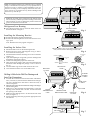
Standard Accessories
10
Installation Bracket
30
Electrical terminal block
6 station
ON
OFF
Absorption cushions
Room Thermostat Unit
Long Screws
Wall Plugs
STBY
User's Manual
Insulation for fittings
Drain hose adapter
Screws and Wall Plug
Electrical Requirements
●
●
●
●
●
The air conditioner must be directly connected to an appropriate power source.
Use only Type "G" or "C" fuses, as appears below:
AVV 25
:
20A
AVV 50
:
25A
Use a single-length power cable, without extensions.
For 1 Phase connection, use 4 wire inter-unit cable.
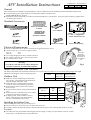
Use special Socket - CEE.
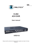
Insert the
drainage
adapter from
the inside of
the outdoor
unit
Warning!
To avoid any risk, if the power cable is damaged, it
should be replaced by an authorized technician.
Fig. 1
Indoor and Outdoor Unit Location
The indoor and outdoor units should be installed as close to each other as possible. Do not exceed the tubing lengths and height
differences which appear in the accompanying table:
Maximum height
Maximum
Model
tubing length difference between
meters (ft) units in meters (ft)
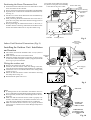
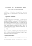
● Make sure to leave sufficient space around the
AVV 25, 50
18 (59')
25 (81.5')
unit. See Fig. 2 for minimum required distances
between the unit and nearby walls.
● Install the unit in a location with convenient
access for service and maintenance purposes.
● Protect the unit from any heat source such as
a
0.6m
min.
direct sun rays.
DIMENSIONS
0.15m
AVV
AVV
min.
● Prevent from any dust or strong wind installation
0.15m
mm (")
25
50
min.
sites.
● Position the unit to minimize motor noise which
a
320
320
reaches the customer and neighbors.
0.6m
● In heating mode, water can form in the conmin.
641
641
b
0.6m
denser. A drainage hose may be attached to
min.
900
1100
the unit. Use the adapter shown Fig. 1.
c
Outdoor Unit
Installing the Indoor Unit
c
b
When installing the indoor unit, please take care to:
● Allow free access to the service doors, air filter and control box.
● Carefully plan the drainage tube path at a minimum downward slope of 2%, avoiding sharp bends or oil traps.
Location
●
The indoor unit may be installed either hanging from the ceiling or resting on a hard surface (concrete or other).
Refer to Fig. 7 for the dimensions of the indoor unit.
Fig. 2
Note: Avoid indoor/outdoor unit installation above valuable
things, Communications, Electricity or any aparature that is
sensitive to water or wetness. If any Installation is not performed according to the Company instructions the Company will not be responsible for any kind of damages that
will occur by water drops.
1152.6mm
45.37”
576.3mm
22.68”
752.0mm
29.6”
30mm
1.18”
30mm
1.18”
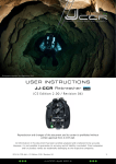
Note! The air intake grill is mounted on the bottom of the
unit. If necessary and also possible according to the installation location, it is easy to change the position of the inlet
grill to the front bottom of the unit.
972.0mm
38.26”
120.2mm
4.7”
1500 mm
59” min.
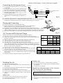
Refrigerant Line Routing
●
The refrigerant lines may be routed in either of the two
directions shown in Figure 3
INSTALLATION
PALETTE
1
Fig. 3
Installing the Mounting Bracket
●
●
Position the pattern supplied with the unit.
Position the mounting bracket on the wall and level it using a spirit
level. Dimensions as they appear in Figure 3.
Installing the Indoor Unit
●
●
●
●
●
●
●
●
Mount the indoor unit on the mounting bracket.
Remove the four screws which appear in Fig. 6 and remove the front bottom panel.
Attache the bottom of the unit using two screws to the wall.
(See Fig. 4).
Open the Diaphragm using knife, pass the drainage tube
through the opening (See Fig 6).
Connect the refrigerant pipe to the indoor unit.
Take out the power supply cable, inter unit cable and room
thermostat cable through the passage cover as shown in
Fig. 6).
Use the rubber rings on the cable exit from the cover.
Close the bottom front cover of the indoor unit.
FRONT VIEW: Two screws at the bottom of the
unit, must be used in attaching it to the wall.
Fig. 4
REFRIGERANT
LINES
Ø 70mm(3")
10mm(0.5")
min.
INDOOR
OUTDOOR
DRAINAGE
TUBE
ELECTRICAL
CABLE
Fig. 5
DRAINAGE
TUBE
BOTTOM
COVER
Drilling A Hole In the Wall For Drainage and
POWER
SUPPLY
CABLE
Inter-Unit Connections
●
●
●
2
4
1
3
3
INTER UNIT
CABLE
4
10
ON/STBY
OFF
ROOM
THERMOSTAT
UNIT
COVER
OPENING FOR
DRAINAGE TUBE
PASSAGE
COVER
Fig. 6
10
30
●
To make the connections between the indoor and outdoor
units, a 70 mm (3") hole should be drilled for the refrigerant lines, drainage hose and electric cables the wall, as
shown in Figure 5.
Mark the center of the hole to be drilled according to the refrigerant line routing used.
Make sure to drill outwards and downwards, so that the
opening in the outside wall is at least 10 mm lower than
the opening on the inside.
Make sure the drainage hose is at the bottom side of the
hole (see Figure 5).
Fill the remaining wall hole gap with an appropriate sealant material.
30
●
ON
OFF
300mm
11.8”
AIR VENT EXIT
RETURN
AIR VENT
1500mm
59”
STBY
300mm
11.8”
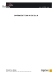
Fig. 7
●
●
●
●
m
6m
~
●
Power cable entry
Arrow showing
wall installation
direction
Locking
pins
m
7
6
5
4
3
2
1 L1 -
●
Position the Room Thermostat Unit on a wall where it will be
most convenient for the customer.
Gently pull out the temperature knob and the ON/OFF handle.
Open the screw on the bottom of the Room Thermostat Unit.
(See Fig. 8).
Pull the cover of the Room Thermostat Unit and drill the appropriate holes in the wall.
After positioning the Room Thermostat unit on the wall, replace the cover gently and ensure that the locking pins are in
the correct position. .
When positioning the Thermostatic Room on the wall, remember that the connecting cable between the Room Thermostat unit and the indoor unit is only three meters long.
Cover plate for the cable entry passage
way. Remove this plate when installing
a wall duct for the power cable.
-6m
10
30
Positioning the Room Thermostat Unit
Temperature
Knob
ON
STBY
OFF
ON/OFF
Locking Screw
Fig. 8
Inter-unit
Electric Cable
Clamp
Indoor Unit Electrical Connections (Fig. 9)
Installing the Outdoor Unit Installation
and location
●
●
●
The outdoor unit must be installed a least 5 cm (2") above a
solid surface.
Drainage
Make sure that the unit is horizontal leveled.
Tube
Fasten the outdoor unit supports to the base, as shown in Fig.
10. Place the rubber absorption cushions (supplied) under the
unit’s legs to prevent vibrations.
Wiring the outdoor unit
●
●
●
●
Power Supply
Cable
Inter Unit
Cable
10
30
●
Remove the outdoor unit plastic side cover.
Attach the inter-unit electric cable with mating connectors,
using the electrical terminals supplied with the air-conditioner.
Connect the wires in accordance with the color coding which
appears in Fig. 11.
Secure the inter-unit electric cable to the outdoor unit using
the clamp shown in Fig. 10.
Reassemble the plastic side cover.
ON
STBY
OFF
Fig. 9
Room Thermostat Unit
1PH ~
NEUTRAL
Notes:
● A drainage tube can be connected to the outdoor unit to remove condensation formed during heating mode operation.
● When possible, lead the indoor unit drainage tube to the outdoor unit.
● Make sure that the inter-unit electric cable is properly connected to the outdoor unit, in accordance with the color coding in the wiring diagram attached to the air conditioner.
● Make sure that all screws and wires are properly fastened.
Loose wires or connections can cause damage and present a
fire hazard!
L1 - ~
L2- 0
COMP.
S(3p
T(3p
INTER-UNIT
ELECTRIC
CABLE CLAMP
4 ABSORPTION
CUSHION TO BE
PUT UNDER EACH
LEG
Fig. 10
Indoor Power Supply 1-Phase Electrical Diagram
Connecting the Refrigerant Lines
●
●
●
●
●
●
●
1-Phase
Power Cable
To connect the refrigerant lines use "L" type sealed,
or equivalent.
Do not open service valves or remove protective caps
from tubing ends until all the connections are made.
Take care to avoid kinks or flattening of the tubing.
Bend tubing with special bending tools to avoid the
formation of sharp bends.
Keep the tubing free of dirt, sand, moisture and other
contaminants to avoid damaging the refrigerant system.
0
Indoor
Unit
Outdoor
Unit
WHITE
BLUE
BROWN
MOTOR, COMPRESSOR RELAY
NEUTRAL
PHASE
GREEN/YELLOW
Fig.11
OUTDOOR SENSOR CABLE (TH3)
Avoid sags in the suction line to prevent the formation of oil traps.
Insulate the tubing with 3/8"- walled thermal pipe insulation. You can save time and improve
insulation by inserting the tubing into the insulation before making the connections.
Flaring and Connecting
●
●
●
●
●
Remove the protective cap from the flare fitting.
Remove the protective cap from the tubing and cut to the required length.
Make sure that the cut is perpendicular and clean, without burrs.
Slip the flare nut on the tubing and flare the tube end, using standard flaring tools.
Tighten the nut until resistance is met. Mark the nut and the fitting. Using a suitable wrench,
tighten an additional 1/4 turn. Use the following specified torque, according to connection size:
The valves on the outdoor unit must remain closed until all four connections have been made.
Fig. 12
Air Vacuum and Refrigerant Charge
When all the fittings are connected, air must be expelled, as follows:
●
Open the service valve protection cap on the suction line valve (large valve).
●
Connect the vacuum pump to the service port via the pressure gauge and operate the
pump for 15 minutes.
●
Make sure that full vacuum is present and disconnect the vacuum pump.
●
Open the liquid line valve (small valve) with an Allen wrench.
●
Open the suction line valve (large valve) with an Allen wrench.
●
The outdoor unit is supplied with sufficient refrigerant for eight meters (26 feet) of
tubing. Add refrigerant and oil according to the table for each additional meter of
tubing used. If the tubing is shorter than 8 meters, release gas from the system through
the service valve into a recycling device.
●
Close the service valve protection cap of the suction line.
Tubing
●
Make sure that the valves are properly opened. Be careful not to open them
Line
more than required, as this may damage the thread.
(")
●
Replace the stem cap. Oil the valve protection cap and hand tighten the cap,
3/8"-5/8"
until resistance is met. Use a suitable wrench to tighten the cap by an additional 1/6 turn.
●
Check the system for refrigerant leakage using a leak detector.
Finishing the job
●
●
●
●
●
●
●
Hide the tubing where possible.
Make sure that the drainage tube slopes downwards along its
entire length.
Insulate tubing connections with the insulation sleeves supplied.
Fasten tubes to the outside wall.
Seal the hole through which the cables and tubing pass.
Connect the air conditioner to the power source and turn it on.
Check all air conditioner operating modes. Consult the User
Manual.
Indoor unit
●
●
●
Do all the remote controller buttons function properly?
Do the Room Thermostat unit lights work properly?
Does the drainage work?
Valve Type
Liquid
Small
Suction
Large
Tubing
Line (")
1/4"
3/8"
3/8"
1/2"
5/8"
3/4"
Torque
kg m lb ft
1.7
12.3
4
29
4
29
5
36
6.5
47
10
72
Add refrigerant and oil if tubing is longer than
8m (26'3"), for each additioinal 1 meter (3'33") add:
Refrigerant gr. / Oz
Oil gr. / Oz
30
1.05
10
0.35
Outdoor unit
●
●
●
Are there unusual noises or vibrations during operation?
Is noise, drain water or air flow from the unit likely to disturb
the neighbors?
Are there any gas leakages?
Explain the following items to the customer,
with the aid of the User Manual:
●
●
●
How to turn the air conditioner on and off.
Warning! Before any maintenance, disconnect the power
supply cable from the unit.
How to remove and clean the air filter and adjust the air deflectors.
Provide the User's Manual and this installation sheet to the
customer.