1
TGL - 5130-26135-75-C
50Hz TAC 505 TAC 506 0101
VER - F
TGL/DGL Installation Instructions
General
These instructions are intended as general guidelines. The air conditioner must be installed by trained and authorized personnel.
Use the following size copper tubing for connecting the outdoor and indoor units:
Models TGL/DGL 9, 11 - 3/8" and 1/4". Models TGL/DGL 15, 20, 25 - 1/4" and 1/2". Models TGL 30 - 3/8" and 5/8".
● Installation must be performed in accordance with the manufacturer’s specifications, using only approved tubing, original electrical
cables and accessories.
6/7 stations according
to the model
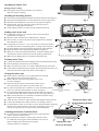
Standard Accessories
Electrical terminal block
Long Screws
●
●
S TA R T
STOP
1 2 3 SLEEP
D A I LY
MODE
Mounting Bracket
Absorption cushions
for DGL and TGL 30
Drain hose adapter
for DGL/TGL 30
Outdoor sensor TH3,
10m connecting cable
Drain hose adapter
for DGL/TGL 9-25
Insulation for Fittings
Electrical Requirements
●
●
●
●
Wall Plugs
User's Manual
Model
The air conditioner must be directly connected to an
appropriate power source.
Use 16A fuses for all Models TGL/DGL air conditioners. TGL-9, 11, 15, 20, 25, 30
Use a single-length power cable, without extensions.
DGL-9, 11, 15, 20
When installing a Dual System air-conditioner of DGL
series (a single outdoor unit and two separate indoor units) DGL-11/15
both indoor units must be connected to the mains power
supply in order for the system to function properly.
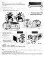
Indoor and Outdoor Unit Location
The indoor and outdoor units should be installed as
close to each other as possible. Do not exceed the tubing
lengths and height differences which appear in the accompanying
table above:
Outdoor Unit
●
a
0.15m(6")
min.
Maximum tubing
length in meters (ft)
15 (49')
15 (49')
15 (49')
●
●
●
●
●
●
●
Insert the
drainage
adapter
from the inside
of the outdoor
unit
a
0.15m(6")
min.
0.6m(2')
min.
0.15m(6")
min.
Make sure to leave sufficient space around the unit. See Figure 1 for
minimum required distances between the unit and nearby walls.
b
c
b
Install the unit in a location with convenient access for service and
c
maintenance purposes.
Position the unit to minimize motor noise which reaches the customer
Fig. 1
TGL 9-25
DGL, TGL 30
and neighbours.
In heating mode, water can form in the condenser. A drainage hose may
Outdoor
Model
be attached to the unit. Use the adapter shown Figure 1.
Dimensions
TGL 9-25
TGL 30
For opening service door in models TGL 9-25, keep a minimum distance of
mm (")
Plastic Model DGL ALL
0.27m (10" 62') between the unit and the support's end.
a
320 (12.59") 265 (10.43")
Make sure of installing the unit legs to the support.
b
641 (25.23") 540 (21.25")
Indoor Unit
●
Maximum height
difference between unit
in meters (ft)
10 (33')
10 (33')
10 (33')
0.6m(2')
min.
m(
2
mi ')
n.
●
Remote Controller
and Batteries +
Remote Controller
Rack
0.6m(2')
min.
0.6
●
SWEEP
WIRELESS DIGITAL REMOTE CONTROLLER
WIRELESS DIGITAL REMOTE CONTROLLER
Insert the
drainage
adapter
from the outside
of the outdoor
unit
0.15m(6")
min.
FA N
0.6m(2')
min.
0.6m(2')
min.
c
1100 (43.3") 730 (28.74")
Make sure to leave sufficient space around the unit. See Figure 2 for minimum
required distances between the unit and the ceiling, floor and surrounding walls.
Locate the unit to ensure free air flow around it.
A 120 cm. power cable is supplied with the unit. We recommend placing the power
0.15m (6") min. a
outlet near the unit, on its right side.
Avoid installing the unit near a
Indoor
Model
0.2m
b 0.2m
source of heat, such as direct
(8")
(8")
Dimensions
TGL 9-20
TGL 25-30
min.
min.
sunlight, steam or a flame.
mm (")
Install the unit in a location
c
a
185 (7.28")
185 (7.28")
1.8−2.5m
with convenient access to
(6'-8'3") min.
refrigerant line connections
b
260 (10.23") 295 (11.61")
for service and maintenance
c
815 (32.08") 1080 (42.52")
Fig. 2
purposes.
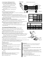
Installing the Indoor Unit
Refrigerant line routing
● The refrigerant lines may be routed in any of the four
directions shown in Figure 3.
2
1
3
Installing the mounting bracket
●
●
●
●
●
4
Pull out the mounting bracket attached to the back of the unit. See Figure 4.
Position the mounting bracket on the wall and level it using a spirit level.
Mark the four drilling holes on the wall, as they appear in Figure 4.
Drill the holes, insert the wall plugs and use the long screws to
attach the mounting bracket to the wall.
Check that the bracket is level and securely fastened to the wall.
Fig. 3
Drilling a hole in the wall
●
●
●
●
●
●
●
●
If refrigerant routing No. 3 is chosen, a hole in the wall must be
perform shown in Figure 6.
Mark the center of the hole to be drilled shown in Figure 4.
Drill a 70 mm (3") hole in the wall for the refrigerant lines, drainage
hose and electric cables.
If refrigerant line route nos. 1, 2 or 4 are used, use a small saw blade to
carefully remove the corresponding plastic covering on the side panel.
Fill the remaining wall hole gap with an appropriate sealant material.
Mount the indoor unit on the mounting bracket (see Figure 6).
Make sure to drill outwards and downwards, so that the opening in the
outside wall is at least 10 mm lower than the opening on the inside.
Make sure the drainage hose is at the bottom side of the hole.
50 mm (1”96’)
40 mm
(1”57’)
Fig. 4
Drainage water form
●
●
●
●
Connect the unattached end of the drainage tube to the drainage hose outlet.
Seal the drainage connection to prevent leakage.
Make sure there are no kinks, "U" bends or flattened sections in the tube.
Check that the drainage functions properly. Fill the pan below the unit’s coil
with water and observe that freely drains out. See Figure 5.
FUSE
POWER/AIRCOND
Wiring the indoor unit
●
●
●
●
●
●
●
●
●
FILTER
Remove the air conditioner cover by lifting the lower part and
then pulling it gently outward. See Figure 8.
Remove the two screws from the plastic control cover
Ø 70mm(3")
as shown in Figure 9.
Route the inter-unit electric cable and the outdoor sensor
cable towards the lower right corner of the indoor unit.
For TGL 25/30 model use a screwdriver to insert the bracket pad wire
INDOOR
ends (7 mm) into the terminal block, as shown in Figure 9.
For TGL 9-20 and DGL models insert the bracket pad wire ends into
the terminal block and make sure that the screws are properly fastened.
Make sure that the wires are connected in accordance with the wiring
diagram on the inside of the front cover.
Attach the inter-unit electric cable with the cable clamp located on the unit.
Connect the Outdoor Sensor TH3 connector to its mating connector.
Close the Plastic control cover with two screws. Keep the Electric cable and
Outdoor sensor cable in between. See Figure 9. If plastic control cover
will close not properly the wiring and cover could be damaged!
Fig. 5
OUTDOOR SENSOR
CABLE
REFRIGERANT
LINES
10mm(0.5")
min.
OUTDOOR
ELECTRICAL
CABLE
DRAINAGE
TUBE
Fig. 6
1
Mount the indoor unit
on the mounting bracket
Attaching the Remote Controller Rack
●
●
Use the two screws supplied to attach the rack to the wall in the
location selected by the customer.
Please inform the customer to ensure proper operation of the
air conditioner timer program, there should be a clear "line of
sight" available at all times between the remote
controller and the air conditioner.
TIMER
IR
RECEIVER
2
Gently push with
the arrow direction
Fig. 7
Piping
●
●
Connect the ends of the refrigerant lines to their appropriate fittings,
following the guidelines in the "Connecting the refrigerant lines" section.
Make sure the drainage hose is at the bottom side of the wall through-hole
(see Figure 6).
Installing the outdoor unit
●
●
●
The outdoor unit must be installed a least 5 cm (2") above a solid surface.
Fig. 8
Make sure that the unit is level.
For DGL and TGL-30 models fasten the outdoor unit legs to the base, as shown in Figure 10a. Place the rubber absorption cushions
(supplied) under the unit’s legs to prevent vibrations.
TGL 9-25/DGL
❙ Connection 7 (CONT.) in Figures 9, 10, 10a
and 11 is only for model TGL 30.
TGL 30
*
7mm
6
4
3
2
1
7
6
4
3
2
1
TH3
TH3
TH2
TH1
TH2
TH1
FUSE
POWER/AIRCOND.
PRESS.
COMP.
IMPED
PRESSURE
COMPRESSOR
IMPEDANCE
TIMER
FILTER
AUTO
OFF
REMOTE
IR
RECEIVER
AUTO
OFF
REMOTE
MER
POWER/AIRCOND
TIMER
LTER
FILTER
IR
RECEIVER
Fig. 9
Plastic control cover
Wiring the outdoor unit
●
TGL 9-25
DGL, TGL 30
Remove the 3 screws of the service
door plastic side cover in the
outdoor unit.
Open the service door
(plastic cover).
Attach the electrical terminals
*7 6 4 3 2 1
*
supplied to the inter-unit
electric cable wires.
TH3Outdoor sensor
Connect the wires to the
terminal block male-female,
in accordance with the color
coding which appears in Figure 11.
Absorption
Connect the outdoor sensor cable TH3,
Fig. 10
Cushion x4
making sure the connector is properly
inserted.
For DGL, and TGL 30 secure the interunit electric cable to the outdoor unit with the clamp shown in Figure 10a.
For TGL 9-25 secure the inter-unit electric cable in between the plastic pins shown in Figure 10.
Reassemble the plastic side cover.
FAN~
●
COMP~
RVS
FAN 0
Neutral
Cont.
●
1
2
3
4
6
7
HI
Com
RVS
Me
Low
Neu
Con
Neutral FAN0 FAN~ RVS Comp~
2
)
S(3ph
h)
T(3p
3
ral
Neut
act
Cont
1
RVS
4
speed
Med
5
speed
Low
HI speed
p
Com
6
1
3 2mp~FAN~
6utral 4FAN0 RVS Co
7
8
9
Ne
●
●
●
●
●
Fig. 10a
Notes:
● A drainage tube can be connected to the outdoor unit to remove condensation formed during heating mode operation.
Drainage hose adapter for TGL 9-25 is installed from the outside of the outdoor unit. Drainage hose adapter for TGL 30 and DGL
is installed from the inside of the outdoor unit.
● When possible, lead the indoor unit drainage tube to the outdoor unit.
● Make sure that the inter-unit electric cable is properly connected to the outdoor unit, in accordance with the color coding in the wiring
diagram attached to the air conditioner.
● Make sure that all screws and wires are properly fastened. Loose wires or connections can cause damage and present a fire hazard!
Connecting the Refrigerant Lines
●
●
●
●
●
●
●
INDOOR 1-PHASE
POWER CABLE
Flaring and Connecting
●
●
●
●
●
1 PHASE ELECTRICAL DIAGRAM
To connect the refrigerant lines use only "L"
type sealed, dehydrated copper refrigerant
OUTDOOR UNIT
INDOOR UNIT
tubing. No other type of tubing may be used.
BLACK
FAN HIGH
Use of other types of tubing will void the
BROWN
PHASE (COMP.)
YELLOW
manufacturer’s warranty.
HEAT PUMP
RED
FAN LOW
Do not open service valves or remove protecBLUE
NEUTRL
tive caps from tubing ends until all the connecWHITE
PHASE (CONT.)*
tions are made.
GREEN/YELLOW
Take care to avoid kinks or flattening of the
tubing.
OUTDOOR SENSOR CABLE (TH3)
Bend tubing with special bending tools to
Fig. 11
avoid the formation of sharp bends.
Keep the tubing free of dirt, sand, moisture and other contaminants to avoid
damaging the refrigerant system.
Valve Type
Tubing
Torque
Avoid sags in the suction line to prevent the formation of oil traps.
Line (")
kg m
lb ft
Insulate the tubing with 3/8" - walled thermal pipe insulation. You can save time
Liquid
1/4"
1.7
12.3
and improve insulation by inserting the tubing into the insulation before making
Small
3/8"
4
29
the connections. The suction and liquid lines should never come in direct contact.
Suction
3/8"
4
29
Large
1/2"
5
36
Remove the protective cap from the flare fitting.
Remove the protective cap from the tubing and cut to the required length.
Make sure that the cut is perpendicular and clean, without burrs.
Slip the flare nut on the tubing and flare the tube end, using standard flaring tools.
Tighten the nut until resistance is met. Mark the nut and the fitting.
Tubing
Using a suitable wrench, tighten an additional 1/4 turn.
Line
Use the following specified torque, according to connection size:
The valves on the outdoor unit must remain closed until all four connections
(")
have been made.
Air Vacuum and Refrigerant Charge
1/4"-3/8"
1/4"-1/2"
5/8"-3/8"
3/4"-3/8"
When all the fittings are connected, air must be expelled, as follows:
● Open the service port cap on the suction line valve (large valve).
● Connect the vacuum pump to the service port via the pressure gauge
and operate the pump for 15 minutes.
● Make sure that full vacuum is present and disconnect the vacuum pump.
● Open the liquid line valve (small valve) with an M-5 Allen wrench.
● Open the suction line valve (large valve) with an M-5 Allen wrench.
● The outdoor unit is supplied with sufficient refrigerant for eight meters (26 feet) of
tubing. Add refrigerant and oil for each additional meter of tubing used according
to the table. If the tubing is shorter than 8 meters, release gas from the system
through the service valve into a recycling device.
● Close the service port caps on the suction line.
● Make sure that the valves are properly opened. Be careful not to open them more
than required, as this may damage the thread.
● Replace the stem cap. Oil the cap beam and hands tighten the cap, until resistance is met.
Use a suitable wrench to tighten the cap by an additional 1/6 turn.
● Check the system for refrigerant leakage using a leak detector.
Finishing the job
●
●
●
●
●
●
●
Hide the tubing where possible.
Make sure that the drainage tube slopes downwards along its
entire length.
Insulate tubing connections with the insulation supplied.
Fasten tubes to the outside wall.
Seal the hole through which the cables and tubing pass.
Connect the air conditioner to the power source and turn it on.
Check all air conditioner operating modes. Consult the User's
Manual.
Indoor unit
● Do all the remote controller buttons function properly?
● Do the display panel lights work properly?
● Does the air deflection louver function properly?
● Does the drainage work?
5/8"
3/4"
6.5
10
47
72
Add refrigerant and oil if tubing is longer than
8m (26'3"), for each additioinal 1 meter (3'33")
add:
Refrigerant gr. / Oz
Oil gr. / Oz
15
0.52
10
0.35
20
0.7
10
0.35
30
1.05
10
0.35
30
1.05
20
0.7
Fig. 12
Outdoor unit
● Are there unusual noises or vibrations during operation?
● Is noise, drain water or air flow from the unit likely to
disturb the neighbors?
● Are there any gas leaks?
Explain the following items to the customer, with the aid of
the User Manual:
● How to turn the air conditioner on and off; selecting cooling,
heating and other operating modes; setting a desired
temperature; setting the timer to automatically start and stop
air conditioner operation; and the other features of the remote
controller and display panel.
● How to remove and clean the air filter.
● How to set the air deflection louver.
● Present the User Manual and this installation sheet to the
customer.