1
SmartStorm Irrigation Controller™ Users Manual
Table of Contents
Section 1: Introduction......................................................................................................................................... 5
1.1 Connectors & Indicators......................................................................................................................... 6
1.2 Part Numbers and Accessories.............................................................................................................. 7
Section 2: Installation and Connections............................................................................................................. 8
2.1 Installation Notes.................................................................................................................................... 8
2.2 Mounting.................................................................................................................................................. 8
2.3 Making Connections............................................................................................................................... 8
2.3.1 Power Supply.................................................................................................................................... 10
2.3.2 Solenoid Valve Connections............................................................................................................. 10
2.3.3 Internal Fuse..................................................................................................................................... 11
2.3.4 Input Connection............................................................................................................................... 12
2.3.5 Temperature Sensor Connection...................................................................................................... 12
2.3.6 Network Connection......................................................................................................................... 13
2.3.7 Security............................................................................................................................................. 13
Section 3: Configuration and Setup.................................................................................................................. 14
3.1 Establishing Communications for Setup............................................................................................ 14
3.1.1 Basic Method: Assign a Temporary IP Address to the Configuration Computer ...............................14
3.1.2 Advanced Method: Assign a Temporary IP address to the SmartStorm Irrigation Controller............18
Section 4: Setup Pages...................................................................................................................................... 20
4.1 Main Tab................................................................................................................................................. 20
4.1.1 Network Tab...................................................................................................................................... 21
4.2 Advanced Network Tab......................................................................................................................... 24
4.2.1 Remote Services.............................................................................................................................. 26
4.3 Password Tab........................................................................................................................................ 27
4.4 Date/Time Tab........................................................................................................................................ 29
4.4.1 Manual Time Configuration............................................................................................................... 30
4.4.2 NTP Time Configuration.................................................................................................................... 30
4.5 Logging Tab........................................................................................................................................... 32
4.5.1 Inputs Tab......................................................................................................................................... 33
4.5.2 Attaching a Rain Sensor................................................................................................................... 33
4.5.3 Temperature Tab............................................................................................................................... 34
4.6 Zones Tab............................................................................................................................................... 35
4.7 Programs Tab........................................................................................................................................ 36
4.8 Advance Settings Tab........................................................................................................................... 38
4.9 Control Page Setup Tab........................................................................................................................ 39
Section 5: Operation........................................................................................................................................... 40
5.1 Browser Operation................................................................................................................................ 40
5.2 Manual Operation.................................................................................................................................. 42
5.3 XML Operation....................................................................................................................................... 43
5.3.1 Monitoring......................................................................................................................................... 43
5.3.2 Control.............................................................................................................................................. 44
5.3.3 Program Control............................................................................................................................... 44
5.3.4 Set Run Mode................................................................................................................................... 45
5.3.5 Password.......................................................................................................................................... 45
Page 2
Xytronix Research & Design, Inc.
SmartStorm Irrigation Controller™ Users Manual
Appendix A: Restoring Factory Default Settings............................................................................................. 46
Appendix B: Installing New Firmware............................................................................................................... 47
Appendix C: Accessing the SmartStorm Irrigation Controller™ Over the Internet......................................49
Appendix D: Log Files........................................................................................................................................ 53
Appendix E: External Server and Remote Services........................................................................................ 55
Appendix F: Specifications................................................................................................................................ 57
Appendix G: Trademark and Copyright Information........................................................................................ 59
Appendix H: Warranty........................................................................................................................................ 60
Appendix I: FCC Statement................................................................................................................................ 61
Appendix J: Mechanical Dimensions................................................................................................................ 62
Xytronix Research & Design, Inc.
Page 3
SmartStorm Irrigation Controller™ Users Manual
X-340 SmartStorm Irrigation Controller User Manual Revisions
Revision Description
1.0
Initial release
1.1
Fixed input logic for the ON/OFF switch feature.
Page 4
Xytronix Research & Design, Inc.
SmartStorm Irrigation Controller™ Users Manual
Introduction
Section 1: Introduction
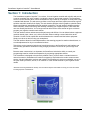
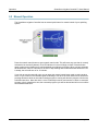
The SmartStorm Irrigation Controller™ is a robust, 10-zone irrigation controller with a built-in web server.
It can be controlled over any IP network, including the Internet* and private networks. The SmartStorm
excels in its web interface which can be accessed from any location by a computer or smart phone using
a standard web browser. The web server provides a much larger and more helpful screen than a typical
sprinkler controller's small built-in display. The web interface provides colorful graphics, schedule charts,
buttons and features unavailable with older sprinkler controllers. The web interface simplifies creating
water schedules, sensor monitoring, and manually controlling your irrigation system. These tasks are
now user friendly and intuitive. You no longer need to reference the users manual to figure out how to
program your irrigation controller each season.
The web interface makes maintenance and repairs easy and efficient. You can isolate broken equipment
(sprinkler heads, pipes, valves, etc.) while in the field, without needing a second technician at the
controller. You don't need to walk back and forth between the controller and the broken equipment.
Simply turn valves on and off using your smartphone.
The web interface allows for instant adjustments to the watering program for weather-related issues, or
to make adjustments for dry or over-watered sections.
Technicians or other personnel who do not have direct access to the SmartStorm's web interface can
also manually operate the SmartStorm using a single push button on the unit to cycle through each
station.
Because water conservation is so important, the SmartStorm includes the ability to control your
programming based on rainfall and temperature by connecting appropriate sensors.
The SmartStorm is designed to be extremely reliable! Even if you don't have a constant Internet or
network connection, SmartStorm will continue to operate by itself without the need to access remote
servers. No paid subscription services and needed. The SmartStorm is easy-to-use whether you are in
the yard, inside your home, at work, or on vacation. It is the ultimate solution to your irrigation control
needs!
*Note that accessing SmartStorm remotely over the Internet requires the installer to setup your router to forward
incoming requests to SmartStorm.
Xytronix Research & Design, Inc.
Page 5
Introduction
SmartStorm Irrigation Controller™ Users Manual
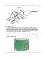
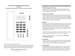
1.1 Connectors & Indicators
Power and Solenoid Valve Connections
The 14-pin connector located on the bottom of the module provides connections for a 24VAC power
source and up to ten solenoid water valves. Zones 9 and 10 can be programmed for a master-valve or
pump start relay if needed. There are two common pins for completing the valve wiring circuit.
I/O Connector
A 5-position removable connector provides connections for sensor inputs, manual control inputs, and a
temperature sensor
Network Connector
The 10/100 Base-T Ethernet connector on the right side provides communication with a computer,
private network, or the internet.
Indicators
Ten yellow LEDs indicate when each zone is energized. The green power LED indicator is illuminated
when AC power is present.
Ethernet Indicators
The green LINK LED is illuminated when the module is properly connected to an Ethernet network and
is ready to communicate. Network communications will only occur if this LED is illuminated. The ACT
LED flashes amber when activity is detected on the network.
Manual Button
Press the manual control button to enter manual control mode. This will cause any zone that is currently
activated to be turned off (aborted). The LED indicator of a zone will begin to flash. Press the button
again to advance the flashing zone until the desired zone indicator is blinking. When you have selected
the desired zone, wait for a moment for the LED to stop blinking and remain illuminated. When the LED
is steady, the zone will turn on for 15 minutes.
If you wish to stop the zone mid-cycle you can press the manual control button again to select another
zone, or cycle it until no LED indicator lights are blinking to turn all of the zone valves off. Be aware that
pressing this button while an automatic watering program is running will abort the program until the next
scheduled start time. Note also that if a valve is manually turned on and remains on when an automatic
program cycle is scheduled to start, the automatic program cycle will be aborted and will not run until the
next scheduled start time.
Page 6
Xytronix Research & Design, Inc.
SmartStorm Irrigation Controller™ Users Manual
Introduction
1.2 Part Numbers and Accessories
Device
Description
Part Number
X-340
Standard SmartStorm Irrigation Controller™ with built-in web X-340-A
server, and ten zones
Temperature Sensor Digital temperature sensor with 12 inch wire leads
Note: Leads may be extended
(for indoor or protected locations only)
X-DTS-U
Temperature Sensor Digital temperature sensor with 3 foot wire leads housed in
submersible stainless steel probe
X-DTS-S3C
Temperature Sensor Digital temperature sensor with 32 foot wire leads housed in
submersible stainless steel probe
X-DTS-S32C
Power Supply
Wall Transformer
120VAC in, 24VAC out, 12VA
(For installations with one 7VA solenoid valve)
PS24VWA0.5
Power Supply
Wall Transformer
120VAC in, 24VAC out, 40VA
(For installations with up to two 7VA solenoid valves)
PS24VWA1.67
Xytronix Research & Design, Inc.
Page 7
Installation and Connections
SmartStorm Irrigation Controller™ Users Manual
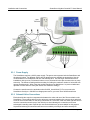
Section 2: Installation and Connections
Installation consists of mounting the SmartStorm Irrigation Controller, making wiring connections to a
power source, connecting the solenoid valves, connecting the Ethernet network, and configuring via a
web browser. Optional rain and temperature sensors can be connected using the 5-position terminal
connector.
2.1 Installation Notes
•
•
•
•
•
This unit must be installed by qualified personnel.
This unit must be installed in a protected enclosure if installed outdoors.
Mis-wiring could cause permanent damage to the SmartStorm Irrigation Controller, the sprinkler
equipment it is connected to, or both.
Do not connect the SmartStorm directly to a 120VAC line voltage power source, you must use a
24VAC transformer.
Do not connect a power source to the sensor inputs.
2.2 Mounting
Mount the SmartStorm Irrigation Controller to a wall by using two #8 screws. Hold the module to the wall
and use a pencil to mark the location of the holes on the tabs on each side. Attach the screws to the
wall, and then hang the module.
See Appendix J: Mechanical Information for additional mechanical details.
2.3 Making Connections
Removable terminal connectors are provided for making connections. The correct wiring procedure is as
follows:
1. Make sure power is turned off.
2. Remove the terminal connector from the SmartStorm Irrigation Controller and make wiring
connections to the terminals. This technique avoids stressing the internal components while
torquing the screws.
3. Reconnect the terminal connector.
4. Apply power.
Page 8
Xytronix Research & Design, Inc.
SmartStorm Irrigation Controller™ Users Manual
Installation and Connections
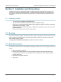
14-Pin Connector
5-Pin Connector
Terminal
Description
Terminal
Description
24VAC_A
24VAC Input A
Input 1
Input 1 IN
24VAC_B
24VAC Input B
Input 2
Input 2 IN
COM
Zone 1-10 COM
Gnd
Ground
COM
Zone 1-10 COM
Data
Temperature Sensor DATA
1
Zone 1
+5Vout
2
Zone 2
Voltage output for Temperature
Sensor
3
Zone 3
4
Zone 4
5
Zone 5
6
Zone 6
7
Zone 7
8
Zone 8
9
Zone 9 (or master)
10
Zone 10 (or master)
Xytronix Research & Design, Inc.
Page 9
Installation and Connections
SmartStorm Irrigation Controller™ Users Manual
2.3.1 Power Supply
The SmartStorm requires a 24VAC power supply. The power source powers both the SmartStorm and
the solenoid valves. Two different 24VAC plug-in transformers are available as accessories. Use the
12VA transformer for installations with one 7VA solenoid valve. Use the larger 40VA transformer for
installations with up to two 7VA solenoid valves or one 7VA solenoid valve plus a master valve or pump
start relay. The Advance Settings tab has a setting for limiting the maximum number of valves that can
operate simultaneously. When using the smaller transformer set MaxValves=1 to prevent inadvertent
operation of more than one zone (See Section 4.8 Advanced Settings).
Connect the transformer to the terminals marked 24VAC_A and 24VAC_B. Do not connect the
SmartStorm directly to a 120VAC line voltage power source, you must use a 24VAC transformer.
2.3.2 Solenoid Valve Connections
Each solenoid valve requires a separate wire between the valve and one of the Zone terminals on the
SmartStorm. The remaining wires from the valves are connected together (the common wire) and wired
to one of the Com terminals. For the wiring connections in a valve box, either use water tight wire nuts or
route the connections near the top of the valve box to avoid allowing the connections to become
submerged in standing water. Special wire nuts filled with dielectric gel are available for this purpose.
Unprotected submerged connections will become corroded by electrolysis and will eventually fail.
Page 10
Xytronix Research & Design, Inc.
SmartStorm Irrigation Controller™ Users Manual
Installation and Connections
2.3.3 Internal Fuse
The SmartStorm has an internal fuse to protect both itself, the transformer and the solenoid valves.
When the SmartStorm is properly powered the green POWER indicator should be illuminated. If the
wiring is incorrect or one of the solenoid valves is shorted or defective, the fuse may blow. If the fuse is
blown the green POWER indicator will not light. The fuse is user replaceable and can be accessed by
removing the four screws on the back side of the enclosure and removing the base shell. To provide
continued protection, replace the fuse with one of the same type and rating.
A blown fuse generally indicates that a solenoid valve is faulty or a short exists in the wiring connections.
Solenoid valves can become internally shorted if water penetrates the housing and corrodes the internal
coil. Before replacing the fuse, check all wiring connections as well as the control valves. If replacing
the fuse does not solve the problem, try disconnecting the wire leads to the solenoid valves at the
controller to isolate the problem.
Xytronix Research & Design, Inc.
Page 11
Installation and Connections
SmartStorm Irrigation Controller™ Users Manual
2.3.4 Input Connection
Two discrete inputs can be connected to switches or auxiliary sensors. Third-party sensors can be used
for monitoring rainfall and other conditions. The inputs can be programmed to suspend watering or to
provide manual control.
Connect one wire of the sensor or switch to a digital input terminal (Input 1 or Input 2). Connect the other
wire to the GND terminal. When the contacts are closed the input is connected to GND and the input is
considered to be ON. Switch current is less than 2 mA. The inputs use 5Volt logic and work with simple
switches and relays. Do not connect the digital inputs to a 24VAC source. The inputs will work with cable
lengths up to 50-feet and should not be routed in the same conduit with the solenoid valves or other AC
wiring.
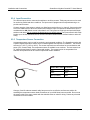
2.3.5 Temperature Sensor Connection
A temperature sensor can be used for monitoring environmental conditions. The SmartStorm works with
a specific digital temperature sensor which is interchangeable and requires no calibration. The sensors
accuracy is +/-0.5°C (-10°C to +85°C). The sensor requires three connections for communications and
power (+5V, Ground, Data). The temperature sensor is available in two versions. The bare sensor has
12” lead wires and must be used in a protected location. The rugged version is encapsulated in a
stainless steel probe and can be used in unprotected outdoor locations.
Sensor Wire Color Connection
Red
+5Vout
Black
GND
Blue (or White)
Data
Category 5 and 5e ethernet network cable has proven to be an effective and low-cost solution for
extending the temperature sensor leads. Extensions of up to 600ft have been successful. Do not route
the sensor cable in the same conduit with the solenoid valves or other AC wiring. Protect any electrical
connections from the weather.
Page 12
Xytronix Research & Design, Inc.
SmartStorm Irrigation Controller™ Users Manual
Installation and Connections
2.3.6 Network Connection
Connect the Ethernet port to an Ethernet hub, switch, or router. For configuration, the SmartStorm may
be temporarily connected directly to the Ethernet port on a computer by using a crossover Ethernet
cable.
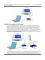
The SmartStorm can be used on a wireless network by making a connection through an Ethernet bridge
or a wireless router.
Note: The wireless Ethernet bridge or router must be properly configured for the wireless network. Refer
to the installation instructions for the wireless device.
2.3.7 Security
The SmartStorm Irrigation Controller does not employ a general purpose computer operating system
and does not have features such as telnet, FTP, SSH, nor uncontrolled open ports. This means it is
unlikely for someone to ‘break in’ to the SmartStorm and access other devices on your local network.
The simplicity of the SmartStorm makes it an inherently secure device. Nevertheless, as with any device
installed on a network, appropriate security precautions should be observed.
If the SmartStorm is installed on the Internet, it is recommended that passwords be enabled for the
Control Page. Passwords should be at least 8 characters in length and use a combination of upper and
lower case letters and numbers. For additional security, a firewall may be used to limit access to
selected IP addresses. Another option may be to set up a Virtual Private Network (VPN) between the
network where the SmartStorm resides and the client machine (web browser, another, ControlByWeb™
product, etc.).
Xytronix Research & Design, Inc.
Page 13
Configuration and Setup
SmartStorm Irrigation Controller™ Users Manual
Section 3: Configuration and Setup
3.1 Establishing Communications for Setup
In order to configure the SmartStorm with a web browser interface, the SmartStorm must be connected
to an Ethernet network. This can be done by one of two methods:
Basic Method – Temporarily change the IP address of a connected computer to the match the default IP
address used by the SmartStorm.
-orAdvanced Method – Assign a temporary IP address to the SmartStorm to work on an existing network.
Note: If multiple ControlByWeb™ products are used on the same network, install one at a time and set
the IP address of each unit before connecting the next unit to the network. This avoids having multiple
devices being installed on the network with the same factory default IP address at the same time. If this
approach is used, be sure to clear the arp cache after disconnecting each unit (arp -d).
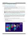
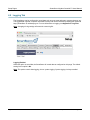
3.1.1 Basic Method: Assign a Temporary IP Address to the Configuration Computer
By default, the SmartStorm comes from the factory with an IP address of 192.168.1.2. Communication
with the SmartStorm may be established by assigning an IP address to the configuration computer so
that it is on the same network as the SmartStorm (for example, the configuration computer could be
assigned to 192.168.1.50)
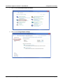
The following example is for those running the Windows-8 operating system:
1. Apply Power, wait 15 seconds for the SmartStorm to become operational, and then connect the
Ethernet cable.
2. Open the Windows 8 start screen.
3. Type “Control Panel” and press enter (the search box opens automatically when you begin typing).
Page 14
Xytronix Research & Design, Inc.
SmartStorm Irrigation Controller™ Users Manual
Configuration and Setup
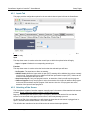
4. Click or touch View network status and tasks.
5. Click or touch Change adapter settings
Xytronix Research & Design, Inc.
Page 15
Configuration and Setup
SmartStorm Irrigation Controller™ Users Manual
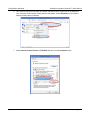
6. Your machine may have more than one Internet connection shown. Right click on the adapter for
your connection to the internet. A drop down box will appear, choose Properties to view/edit the
settings for this internet connection.
7. Select Internet Protocol Version 4 (TCP/IPV4) and then click the Properties button.
Page 16
Xytronix Research & Design, Inc.
SmartStorm Irrigation Controller™ Users Manual
Configuration and Setup
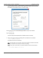
8. If “Use the following IP address” is already selected, the computer has been setup with a static IP
address. Record these values so that the current IP address of the computer can be restored once
the IP address of the SmartStorm has been successfully changed.
Select the radio button labeled "Use the following IP address" and type in the IP address:
192.168.1.50
Type in the subnet mask:
255.255.255.0
No need to change the default gateway field. Click OK to accept the new settings.
9. Open the setup pages by entering the following URL in the address bar of a web browser:
http://{ipaddress}/setup.html
(For example: http://192.168.1.2/setup.html)
Note: If the setup pages are not accessible, verify that the SmartStorm is powered on and that the
LINK light is illuminated. Check all network connections and settings.
Another way to check communications is to ping the SmartStorm from the command prompt by
typing:
ping [ipaddress] (e.g. ping 192.168.1.2)
Xytronix Research & Design, Inc.
Page 17
Configuration and Setup
SmartStorm Irrigation Controller™ Users Manual
3.1.2 Advanced Method: Assign a Temporary IP address to the SmartStorm
Irrigation Controller
This option (arping) is used to TEMPORARILY assign an IP address to the SmartStorm without the need
to change the IP address of the configuration computer. The SmartStorm will use this IP address as long
as power is maintained. Once power is lost, the SmartStorm will use the IP address assigned in the
setup page and not the temporary address assigned here. Make sure that SmartStorm and the
configuration computer are connected to the same network. Since ARP is non-routable, this will not work
through routers or gateways.
3.1.2.1 Microsoft Windows Instructions
1. Open a Command Prompt (select START, then RUN, then type “cmd”).
Note: For Vista, 7, 8, and 8.1, the Command Prompt should be run as administrator (select Start,
then type “cmd” and right click on “cmd” and select “Run as administrator”).
2. Type:
arp -s {new IP address} {serial number of SmartStorm Irrigation Controller }
Note: IP address format is xxx.xxx.xxx.xxx. The serial number can be found on a label on the
module board. The format is ss-ss-ss-ss-ss-ss.
For example, to set the SmartStorm Irrigation Controller (with serial number 00-0C-C8-01-00-01) to
10.10.10.40 the following command would be used:
arp -s 10.10.10.40 00-0c-c8-01-00-01
3. Next, type:
ping -l 102 {new IP address}
For example, if the new IP address is 10.10.10.40, the following command would be used:
ping -l 102 10.10.10.40
4. Proceed with the SmartStorm setup in section 4.
Once setup is complete, it may be necessary to clear the 'arp' cache to configure additional units. This is
necessary because each unit has the same default IP address, but a different unit serial number (MAC
address). Clearing the arp table can be done by typing arp -d in the command prompt window.
3.1.2.2 Linux/Unix Instructions
1. Open a terminal and change to root user (su -, then enter root password).
2. Type:
arp -s {new IP address} {serial number of the SmartStorm Irrigation
Controller}
Note: IP address format is xxx.xxx.xxx.xxx. The serial number can be found on a label on the
module board. The format is ss:ss:ss:ss:ss:ss.
For example, to set the SmartStorm (with serial number 00-0C-C8-01-00-01) to 10.10.10.40 the
following command would be used:
arp -s 10.10.10.40 00:0c:c8:01:00:01
3. Next, type:
ping -s 102 {new IP address}
For example, if the new IP address is 10.10.10.40, the following command would be used:
ping -s 102 10.10.10.40
4. Proceed with the SmartStorm setup in section 4.
Page 18
Xytronix Research & Design, Inc.
SmartStorm Irrigation Controller™ Users Manual
Configuration and Setup
Once setup is complete, it may be necessary to clear the 'arp' cache to configure additional units. This is
necessary because each unit has the same default IP address, but a different unit serial number (MAC
address). Clearing the arp table can be done by typing sudo arp -d -a in the command prompt
window.
3.1.2.3 Mac OS X Instructions
1. Open a terminal.
Note: The terminal is in the “Utilities” directory, which is in the “Applications” directory.
2. Type:
sudo arp -s {new IP address} {serial number of the SmartStorm Irrigation
Controller }
Administrator password may be required.
Note: IP address format is xxx.xxx.xxx.xxx. The serial number can be found on the label on the
module board. The format is ss:ss:ss:ss:ss:ss.
For example, to set a SmartStorm (with serial number 00-0C-C8-01-00-01) to 10.10.10.40 the
following command would be used:
sudo arp -s 10.10.10.40 00:0c:c8:01:00:01
3. Next, type:
ping -s 102 {new IP address}
For example, if the new IP address is 10.10.10.40, the following command would be used:
ping -s 102 10.10.10.40
4. Proceed with the SmartStorm setup in section 4.
Once setup is complete, it may be necessary to clear the 'arp' cache to configure additional units. This is
necessary because each unit has the same default IP address, but a different unit serial number (MAC
address). Clearing the arp table can be done by typing sudo arp -d -a in the command prompt.
Xytronix Research & Design, Inc.
Page 19
Setup Pages
SmartStorm Irrigation Controller™ Users Manual
Section 4: Setup Pages
The SmartStorm Irrigation Controller is configured using a web browser. To access the setup pages,
enter the following URL in the address bar of a web browser:
http://{ipaddress}/setup.html
For example, using the default IP address, enter:
http://192.168.1.2/setup.html
After the page is requested, a password prompt will appear. Enter the username and password. The
default username is admin and the default password is webrelay (password is case sensitive).
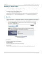
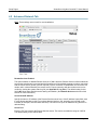
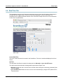
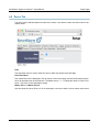
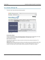
4.1 Main Tab
This is the initial page that is displayed when setup.html is entered into the address bar of the browser. It
displays model and serial number information, and allows the user to configure the temperature sensor.
Part Number
This is the full model number of the SmartStorm.
Firmware Revision
This is the current product revision of the unit's firmware.
Serial Number
This is the serial number of this unit. The serial number is also the MAC address of the unit.
Page 20
Xytronix Research & Design, Inc.
SmartStorm Irrigation Controller™ Users Manual
Setup Pages
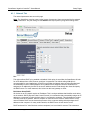
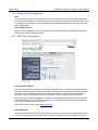
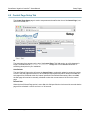
4.1.1 Network Tab
The network parameters are set on this page.
Note: The SmartStorm must be power-cycled (power disconnected, then reconnected) before network
settings take effect. Only the settings on the Network tab require power-cycling before taking effect.
Use DHCP
This option allows DHCP to be enabled or disabled. If this option is set to Yes, the SmartStorm will wait
for an IP address from a DHCP server each time it is powered. The default setting is No (this is
recommended for most installations). If DHCP is set to Yes, the Network page must be submitted and
the SmartStorm must be rebooted before an IP address will be assigned. Once the SmartStorm is
assigned an IP address by the DHCP, the new IP address can be found through the clients list kept by
the DHCP server. For most instances, this is found on the local gateway or router.
Brief Notes About DHCP
All devices on an IP network require an IP address. This is a unique address that identifies each device
on the network. DHCP (Dynamic Host Control Protocol) is a mechanism that automatically assigns an IP
address to a computer (or other devices) when it is connected to a network. This eliminates the need to
manually enter the IP address. When a computer is connected to the network, another device on the
network called a DHCP server detects the presence of the computer and dynamically assigns the IP
address to that computer. On many small networks, the DHCP server is built into the router.
DHCP works well for "client" devices such as computers, but is not ideal for servers. This is because
Xytronix Research & Design, Inc.
Page 21
Setup Pages
SmartStorm Irrigation Controller™ Users Manual
servers usually don't initiate communications with other devices, but rather they wait for a request from
"clients." To make this request, the client must know the IP address of the server. If a server gets its IP
address dynamically, the IP address may not always be the same so client devices may not be able to
find the server. For this reason, servers usually use an IP address that is fixed and does not change.
The SmartStorm is a server and manual IP address assignment is usually recommended.
IP Address
Enter the IP address for the SmartStorm in this field. The IP address is specific to the network where the
SmartStorm will be installed, and must be obtained from the network administrator. For more information
on IP addresses and remotely accessing the SmartStorm over the Internet, see Appendix C:
Accessing the SmartStorm Irrigation Controller Remotely Over the Internet. The default setting for
this field is 192.168.1.2.
Subnet Mask
The subnet mask defines the size of the local network. This must be obtained from the network
administrator. For additional information about sub-netting and IP networking, many tutorials are
available on the Internet. The default setting for this field is 255.255.255.0.
Gateway
This specifies the IP address of the gateway router. This must be obtained from the network
administrator. The default setting for this field is 192.168.1.1.
Preferred DNS Server
The IP address of the Primary DNS server is specified here. When DNS services are required, this is the
address that will be used. The default setting for this field is 192.168.1.1.
This field is only required when the following options are used:
- Remote Services (when server is specified by name and not IP address).
- Sync time clock with remote NTP server (when server name is specified by name and
not IP address).
Alternate DNS Server
This field is used to specify the IP address of a Secondary DNS server. This is used when the
SmartStorm requires DNS services and the preferred DNS server is not available. The default setting for
this field is 192.168.1.1.
HTTP Port
The TCP port used for HTTP communications (web browser, XML, get commands) with the SmartStorm
is specified here. The default setting for this field is 80, which is the standard HTTP port. It is
recommended that the port be left unchanged unless the user has an understanding of TCP/IP and
ports. For more information on TCP ports and IP addressing see Appendix C: Accessing the
SmartStorm Irrigation Controller Remotely Over the Internet.
Speed
This option sets the data rate (clock rate) of the Ethernet port. Either 10 Mbps or 100 Mbps can be
selected. The 100 Mbps option offers faster communications but the amount of data to and from the
SmartStorm is so small that users will not likely notice much (if any) difference. When the SmartStorm is
set to 10 Mbps, it draws less power and runs a little cooler, which may translate into a longer product
life. The default setting for this field is 10 Mbps.
IT IS RECOMMENDED THAT THIS SETTING BE LEFT AT 10Mbps UNLESS THE USER HAS A
SPECIFIC REASON TO USE 100Mbps.
Page 22
Xytronix Research & Design, Inc.
SmartStorm Irrigation Controller™ Users Manual
Setup Pages
Mode
This option allows the Ethernet port to be set to Half Duplex or Full Duplex. Legacy Ethernet operates
in Half Duplex mode which means that devices can either send data or receive data, but not both at the
same time. Full Duplex means that devices can send and receive data at the same time. The default
setting for this field is Half Duplex.
Xytronix Research & Design, Inc.
Page 23
Setup Pages
SmartStorm Irrigation Controller™ Users Manual
4.2 Advanced Network Tab
Note: These settings are not used for most installations.
Remote Services Enabled
This option enables or disables Remote Services. If Yes is selected, Remote Services will be enabled as
soon as the submit button is pressed and the SmartStorm will immediately attempt to make a connection
with the remote server (power cycle not required). Once a connection is established, the connection will
remain until it is disconnected by the remote server. Proper connection with the remote server can be
verified by viewing the system status log file (see Appendix D: Log Files). The default setting for this
field is No. Most users should leave this setting at its default. (See Remote Services at the end of this
section for more information.)
Server Name/IP Address
Specify the name or IP address of the Remote Services server here. If the IP address is specified, enter
it in this format aaa.bbb.ccc.ddd. For numbers that are less than 100, preceding zeros should not be
included (for example, enter 80 rather than 080). This field can be up to 40 characters long and has no
default setting.
Server Port
Enter the TCP port used for the Remote Services server. This can be set within the range of 0-65535.
The default setting for this field is 8000.
Page 24
Xytronix Research & Design, Inc.
SmartStorm Irrigation Controller™ Users Manual
Setup Pages
Connection String
This text is sent to the Remote Services server when the connection is established. This string should
include any information required by the server at connection. For example, it may include an ID number,
customer number, password, etc. The format is entirely dependent upon the server requirements. This
field can be up to 80 characters long. Default text is provided only as an example placeholder. The
default text is [<serialAddress>]:ControlByWeb,X-340.
Connection Interval
This field specifies the periodic interval in which the SmartStorm attempts to connect to the remote
server, or if the SmartStorm is already connected, it is the interval in which the SmartStorm sends the
connection string. This field can be set within the range of 1 to 34452 minutes. The default setting for
this field is 1 minute.
IP Filter Range 1 and IP Filter Range 2
For additional security, the SmartStorm has a simple built-in firewall. If desired, the SmartStorm can be
configured to only allow access to client devices (computers, servers, other ControlByWeb™ devices,
etc) with certain IP addresses. Two IP address ranges are provided and only client devices with
addresses that fall within those two ranges will be allowed access. Devices with IP addresses that fall
outside of those ranges will not receive any response from the SmartStorm. The following are examples.
To allow access from any device (this is the default setting):
IP Filter Range 1:
0.0.0.0
255.255.255.255
IP Filter Range 2:
0.0.0.0
0.0.0.0
To limit access to only one device (address 192.168.1.33):
IP Filter Range 1:
192.168.1.33
192.168.1.33
IP Filter Range 2:
0.0.0.0
0.0.0.0
To limit access to only devices on the local network and one device on the internet (address
10.143.100.32):
IP Filter Range 1:
192.168.1.0
192.168.1.255
IP Filter Range 2:
10.143.100.32
10.143.100.32
Note: The address specified for the Remote Services server (if applicable) is automatically allowed
through the firewall no matter how this is set.
Xytronix Research & Design, Inc.
Page 25
Setup Pages
SmartStorm Irrigation Controller™ Users Manual
4.2.1 Remote Services
Remote Services initiates an outgoing connection to a server at a remote location. This can be used in
an environment where a web server on the Internet provides a custom web page for the SmartStorm
and other ControlByWeb products. Users access the SmartStorm through the web server rather than
communicating directly with it. This method is sometimes referred to as “web services” and allows
programmers to create powerful, custom web pages to multiple devices using the web programming
languages of their choice.
Remote Services initiates the connection to the external web server (rather than the web server initiating
communications to the SmartStorm). This has two main benefits. First, the web server does not need to
know the IP address of the SmartStorm. This means that the SmartStorm can get its IP address
dynamically from a DHCP server, simplifying the installation. Second, since the connection from the
SmartStorm is outgoing, rather than incoming, the local router on the network where the SmartStorm
resides doesn't need to be configured to forward sockets. This also simplifies the installation. Since the
router configuration is not modified, the risk of compromising security on the local network is eliminated.
For more information about the Remote Services see Appendix E: External Server and Remote
Services.
Page 26
Xytronix Research & Design, Inc.
SmartStorm Irrigation Controller™ Users Manual
Setup Pages
4.3 Password Tab
The SmartStorm requires a password to log into the setup pages. The password can be changed on this
page. Additionally, the installer can enable the requirement for a Control Page password.
Setup Password
The Setup Password, which is required to access the setup pages, can be modified by entering a new
password here. Passwords that are 8 characters or longer (up to 13 characters can be entered in this
field) with both alphabetic and numeric characters are recommended. For security purposes, the
password will not be displayed as it is entered. Note that the username required for accessing the setup
pages is admin (all lower case). The default Setup Password is webrelay (also all lower case).
Re-enter Setup Password
When the Setup Password is changed, it must be entered twice. One time in the previous field and a
second time in this field. If the password is not entered identically in both fields, the password will not be
changed.
Enable Control Password
The Control Page can be viewed without entering a password. For security purposes, a password can
be required for access to the Control Page. When this field is set to Yes, a password will be required to
view the Control Page. The default setting for this field is No.
Control Password
When the Enable Control Password option above is set to Yes, this field is used to specify the password
which will be required to access the Control Page. Passwords that are 8 characters or longer with both
alphabetic and numeric characters are recommended. For security purposes, the password will not be
displayed as it is entered. Note that the SmartStorm requires a password, but does not require a user
name to access the Control Page. However, some browsers require that a user name be entered. In
this instance enter none as the user name. The default Control Password is webrelay.
Xytronix Research & Design, Inc.
Page 27
Setup Pages
SmartStorm Irrigation Controller™ Users Manual
Re-enter Control Password
When the Control Password is changed, it must be entered twice. One time in the previous field, and a
second time in this field. If the password is not entered identically in both fields, the password will not be
changed.
Page 28
Xytronix Research & Design, Inc.
SmartStorm Irrigation Controller™ Users Manual
Setup Pages
4.4 Date/Time Tab
The SmartStorm uses the time for program start times, zone run times, and for logging (a time stamp is
included with each logged event). The time is stored and displayed in 24-hour time format. The
SmartStorm has a capacitor-backed real-time-clock circuit that will keep track of time for several weeks
in the event of a power failure.
Current Date/Time
This is the current date and time stored in the SmartStorm. The time is stored and displayed in 24-hour
format.
Set Time
This drop-down list offers two options for setting the time: Manually or Sync with NTP server.
The options that follow this field will change based upon how this option is set.
- Manually requires the user to enter the time and date. When this option is selected, parameters Date
and Time appear.
- Sync with NTP server allows the user to set the clock automatically by using an NTP (Network Time
Protocol) server.
Xytronix Research & Design, Inc.
Page 29
Setup Pages
SmartStorm Irrigation Controller™ Users Manual
4.4.1 Manual Time Configuration
Date
The current date is entered by first selecting the correct month and year, using the left and right arrows
at the top of the calender. The single arrows(< and >) change the month and the double arrows (<< and
>>) change the year. Once the current month and year are displayed, select the correct day, which will
then be highlighted.
Time (24 Hour Format)
Enter the time as HH:MM:SS. (HH represents hours in 24-hour format [00-23], MM represents minutes
[00-59], SS represents seconds [00-59].)
4.4.2 NTP Time Configuration
Server Name/IP Address
This field is used to specify the name or IP address of the NTP server. If a name is specified, a working
DNS server address must be entered into the Network settings. If the IP address is specified, it should
be entered in the following format aaa.bbb.ccc.ddd where each of the letters represents a number
between 0 and 255. This field can be up to 40 characters. There is no default value for this field.
Many NTP Internet servers are available. In addition, many desktop computers will function as an NTP
server (both Mac and PC). If a desktop computer is used, firewall settings may need to be adjusted to
allow for NTP communications on port 123.
Public NTP servers can be found at www.pool.ntp.org.
Sync With Server
This option allows the user to specify how often the SmartStorm time will be synchronized with the time
server. When the submit button on this page is pressed, the SmartStorm will immediately synchronize
Page 30
Xytronix Research & Design, Inc.
SmartStorm Irrigation Controller™ Users Manual
Setup Pages
with the time server. If Daily, Weekly, or Monthly options are selected, the SmartStorm will thereafter resynchronize with the time server at the period interval specified starting at 12:00 AM (00:00).
The exact time the NTP Request occurs is 12:00 AM (00:00) plus the minute equivalent of the last two
digits in the models serial number. For example, if the last two digits in the model's serial number were
-09, the NTP Request will occur 9 minutes after 12:00 AM. The default value of this setting is Once (the
unit will immediately sync with the NTP server, but will not automatically sync again).
Sync on Power Up
When this option is set to Yes, the SmartStorm will be synchronized with the time server each time it is
powered.
Note: If the SmartStorm will lose power on a frequent basis, it may be beneficial to set this option to No;
some servers are configured to dis-allow access from client devices that excessively request their
services. The default value of this setting is No.
UTC Offset
Time servers return the current time in Universal Time (GMT). It is common for many servers and data
loggers to use GMT as their official time, even when they are not located within the GMT time zone. The
default value for this field is -7 (Mountain Standard Time). For convenience, the time can be converted to
local standard time by entering the offset here. This manual cannot include the UTC Offset for all parts of
the world, but the offset for GMT time and the four major US Time zones are listed here.
GMT Time: 0
Eastern Standard Time: -5
Central Standard Time: -6
Mountain Standard Time: -7
Pacific Standard Time: -8
Daylight Savings
In many parts of the United States and in some other countries, the time is shifted forward by one hour
during the summer months. This is an effort to conserve energy by making the daylight last longer into
the evening hours. If this option is set to Yes, the time in the SmartStorm will automatically be shifted
forward by one hour between the hours of midnight and 5:00 AM on the Daylight Savings Start date set
below, and it will shift back to standard time between the hours of midnight and 5:00 AM on the Daylight
Savings End date set below. The time change is made at a pseudo random time (based on the mac
address) within the previously mentioned, five-hour time frame, in order to prevent several different
devices from simultaneously requesting a time and overwhelming the NTP server. The default setting is
Yes.
Note: Enabling the daylight savings time adjustment, scheduled events will be adjusted for the new
time. Logged data includes a time stamp based upon the current time in the device, so it is possible to
duplicate log times in the spring and miss log times in the fall.
Daylight Savings Start
This is the date that daylight savings will start. Note that on this date, between the hours of midnight and
5:00 AM, the current time will be shifted forward by one hour (i.e. the time will jump from 12:02 AM
[00:02] to 1:02 AM [01:02]). By default this is set to the 2nd Sunday in March which is the date used in
the United States.
Daylight Savings End
This is the date that daylight savings will end. On this date, between the hours of midnight and 5:00 AM,
the current time will be shifted backward by one hour (i.e. the time will jump from 12:02 AM [00:02] to
11:02 PM [23:02] the day before). By default this is set to the 1st Sunday in November which is the date
used in the U.S.
Xytronix Research & Design, Inc.
Page 31
Setup Pages
SmartStorm Irrigation Controller™ Users Manual
4.5 Logging Tab
The SmartStorm can be configured to record data such as zone starts and stops, program changes, etc.
The logged data is stored in internal nonvolatile memory and can be retrieved by entering the command
http://{SmartStorm IP address}/log.txt. For more information on logging, see Appendix D: Log Files.
Note: Changing the log settings will erase the current log file.
Logging Enabled
When this option is set to Yes, the SmartStorm will record data as configured on this page. The default
setting for this option is No.
Note: This option controls data logging, but not system logging. System logging is always enabled.
Page 32
Xytronix Research & Design, Inc.
SmartStorm Irrigation Controller™ Users Manual
Setup Pages
4.5.1 Inputs Tab
This page provides configuration options for the two switch closure inputs built into the SmartStorm.
Note: In this manual, the input is considered to be ON when the input is connected to ground with a
switch or relay.
Input
This drop down menu is used to select the control input to which the options below will apply.
- Input 1 or Input 2: Selects the corresponding control input.
Function
This drop down menu is used to select the function that the selected input will have.
- No Function: The input has no affect on watering.
- ON/OFF Switch: When the input switch is open (OFF) watering will be inhibited. Any valves currently
on will turn off. Programs will not turn valves on while the input switch is open (OFF). Valves can be
turned on manually while the input is OFF.
- Stop Current Cycle: If only one program is active, an assertion of the input will stop the program.
- Advance Program: If only one program is active, an assertion of the input will advance the program
to the next Zone and then stop the program if the last zone is active. If no programs are active,
assertion of the input will start program A.
4.5.2 Attaching a Rain Sensor
The SmartStorm Irrigation Controller supports “normally open” rain sensors. Most standard rain sensors
will work. Do not connect the sensor inputs to a 24VAC power source.
Begin by connecting the rain sensor to Input 1 (or Input 2), and the Gnd terminal. Be sure that the
sensor is not connected to any type of power source, as this may damage your unit.
On the Inputs Tab of the setup pages you will choose the input that the rain sensor is plugged into i.e.
Input 1, and then select ON/OFF Switch. Then click Submit.
This will allow the controller to be shut off when the rain sensor detects precipitation.
Xytronix Research & Design, Inc.
Page 33
Setup Pages
SmartStorm Irrigation Controller™ Users Manual
4.5.3 Temperature Tab
This tab is used to configure the low temperature shutoff feature. If no temperature sensor is attached
this feature is automatically disabled. If the low temperature shutoff feature is not wanted (and a
temperature sensor is connected), set the low temperature shutoff to a super low value such as -50°
(max = -67°)
Units
This allows the user to select between the temperature units of Fahrenheit and Celsius. All settings
entered and displayed on subsequent pages will be in the units selected.
Low Temperature Shutoff
This setting is used to set the threshold for the low temperature system shutoff. When the temperature
read from the sensor drops below this threshold the unit will turn off the automatic run mode, this will not
affect your ability to operate the unit manually. Use this feature to prevent ice buildup or damage to the
sprinklers and pipe. You may wish to set the threshold to values in the 40° to 50° range to save water
when grass is not actively growing and needs little water.
Page 34
Xytronix Research & Design, Inc.
SmartStorm Irrigation Controller™ Users Manual
Setup Pages
4.6 Zones Tab
This tab is used to add descriptions for each of the zones. It can also be used to set zones 9 and 10 as
master valves.
Zone
This drop-down menu is used to select the zone to which the options below will apply.
Zone Description
Text entered here will be displayed in the left column of the control page, and should describe the zone.
Up to 24 characters may be entered here. The default text is Zone#. Change the name to “Office Front
Lawn”, “Drip Line” or other descriptive setting.
Master Valve 1 or Master Valve 2
Use this check box (when Zone 9 or 10 are selected) to use zone 9 and/or 10 as a master valve control.
Xytronix Research & Design, Inc.
Page 35
Setup Pages
SmartStorm Irrigation Controller™ Users Manual
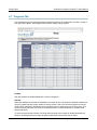
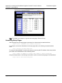
4.7 Programs Tab
The SmartStorm has four separate programs (schedules) that can be configured to run with a variety of
time and output options. The programs tab is used to configure the programs.
Enabled
Use this checkbox to enable/disable each of the four programs.
Stacked
When this checkbox is selected the SmartStorm will check to see if the number of allowed simultaneous
valves is greater than the current number of running valves. If this is the case the program will run the
current valve, otherwise it will add the valve to a queue to be run when the unit is no longer busy. This
mode will ensure that each zone runs for the desired amount of time and attempt to run them at the
desired start times.
If it is not checked and the number of running valves is equal to the number of allowed simultaneous
valves, it will disregard the zone that was called, and will wait until the next zone is called.
Page 36
Xytronix Research & Design, Inc.
SmartStorm Irrigation Controller™ Users Manual
Setup Pages
Days to Water
Use the options here to select the days that you would like to water. All options depend on the day of the
week being checked to run the program and not just the Day of Week option. For example, if the
program is to run on odd days and only Saturday is checked, then the program will only run on
Saturdays that are an odd day of the month. For another example, a local park is frequently used on
Saturday and Sunday all day long and it is best to not water on those days. Checking days M - F will
enable watering only on those days according to settings for interval, even, or odd days.
Day of Week: This will allow you to select the days of the week that you would like to water.
Interval: This will allow you to set an interval for which days you would like to water, i.e. every other
day, every three days, etc. If M-F are checked and interval is every 3 days, the system will only
operate every 3 days when the day falls on M-F.
Even Days: This will set the watering to happen on days with even dates. For example, with “even
days” selected, if Sunday, Monday and Friday are checked, it will only water on those days if they
occur on even days.
Odd Days: This will set the watering to happen on days with odd dates. For example, with “odd
days” selected, if Sunday, Monday and Friday are checked, it will only water on those days if they
occur on odd days.
Start Times
You are able to add up to eight start times for each program. Hours should be entered in 24-hour format
[00-23]. The minutes are entered in the second box [00-59]. The program will run through all the Zones
that have a non-zero run time beginning at each start time.
Interzone Delay
The interzone delay is the time that the SmartStorm will wait between turning off one zone and turning
on the next zone. This time is set in seconds and can range between 0 – 224. The default value is 10.
Note: MV1 and MV2 will also be turned off during the interzone delay. Please plan accordingly if MV1 or
MV2 are being used to control pumps
Run Time
The values that are entered here will determine how long each zone will run. If you don't want a zone to
run, then set the time to 0. Values entered can be between 0 – 224. All the values are set to 0 by default.
MV1 or MV2
Use these checkboxes to turn on main valve 1 or 2 when the corresponding zone is set to run. If the
checkboxes are disabled, you can enable them by setting zone 9 or 10 as a master valve on the Zones
Tab.
Xytronix Research & Design, Inc.
Page 37
Setup Pages
SmartStorm Irrigation Controller™ Users Manual
4.8 Advance Settings Tab
This tab is used to setup the advanced watering options.
Monthly Water Budget
Here you can adjust the monthly overall water budget as a percent [0-100]. The percentage will modify
the time that the zones run as set in the programming tab. The default value is 100%.
Max Simultaneous Valves
The value set here specifies the maximum number of valves that can operate simultaneously. The
default value is 1 [1-2].
Warning: When operating more than one valve at a time make sure you power SmartStorm with a large
enough transformer to support multiple valve operation. Note that enabling stations 9 and/or 10 to
function as a master valve or pump controller requires a transformer for multiple valve support.
Page 38
Xytronix Research & Design, Inc.
SmartStorm Irrigation Controller™ Users Manual
Setup Pages
4.9 Control Page Setup Tab
The Control Page Setup page is used to set parameters that affect the view of the Control Page, how
often it will refresh, etc.
Main Header Text
The text entered here appears at the top of the Control Page. This field can be up to 30 characters in
length. The default text is Sprinkler Controller. Change this to “East Baseball Diamond” or
something descriptive for your installation.
Auto Refresh
The Auto Refresh Page option will cause the Control Page to continually update its contents by setting
a timer in the web page that causes it to be reloaded at a specified time interval. When set to Yes, the
web page will be refreshed at the time interval specified in the Refresh Rate setting. When set to NO,
the web page will need to be manually refreshed to show the current status of the unit in the control
page.
Refresh Rate
When the Auto Refresh Page option is set to Yes, this field specifies the time interval in seconds that the
page will be refreshed. It can be set from 1 to 32 seconds.
Xytronix Research & Design, Inc.
Page 39
Operation
SmartStorm Irrigation Controller™ Users Manual
Section 5: Operation
The SmartStorm Irrigation Controller can be operated using a web browser, using a manual pushbutton,
using the CBW Mobile app, and/or by sending text commands to an XML status/control page. The
watering time can be adjusted using the digital inputs to detect rain or other conditions. (Using a digital
input to control the SmartStorm was described throughout previous sections of the manual, and will not
be described here.)
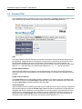
5.1 Browser Operation
Once the SmartStorm is set up, users can access the Control Page using a web browser by typing the
IP address of the SmartStorm into the web browser address bar. For example, using the default IP
address, the user would enter http://192.168.1.2. If the IP address is changed from the default, the user
must use the new IP address. Note that if any port is used other than the default port 80, the port must
also be included in the request. For example, accessing the unit at port 8000 would be as follows:
http://192.168.1.2:8000.
The following screen appears when the Control Page is Selected:
Page 40
Xytronix Research & Design, Inc.
SmartStorm Irrigation Controller™ Users Manual
Operation
Header
Displays the text entered in the Main Header Text field on the Control Page Setup tab in the setup
pages.
Zones 1-10
These rows display the current state of the ten zones as well as the time remaining. The text in the left
column (by default reads Zone 1, Zone 2, etc.) is specified in the Description field in the Zones tab in the
setup pages. The state of the zone is shown to the right of the zone description text. The status text will
read ON or OFF. To the right of the relay status, the time remaining is displayed as HH:MM:SS.
Running Programs
This row displays the currently running programs (A, B, C, D).
Scheduler
This row displays the state of the scheduler. If the scheduler is off it will display, Scheduler Off. This text
will be followed by how it was turned off if it wasn't turned off manually i.e. input1, input2, etc. If the
scheduler is running it will display the current water budget, i.e. Water Budget: 100%.
Temperature
If a temperature sensor is connected, you will see the temperature displayed next, i.e. Temperature:
70.0°F. If a sensor is not attached or is unreadable, this will not be displayed.
Run Mode
This drop down setting allows you to change the state of the scheduler by changing the run mode. If it is
set to Off then the scheduler will not run the configured programs. When it is set to Automatic the
scheduler will be turned on.
Zone
This control allows you to start and stop zones manually. The drop-down box allows you to select which
zone you would like to control. The Stop button will stop the selected zone. The Start button will start
the zone for the time specified in the text box to the right [1-240]. Note that if you start a zone manually
it will abort any running programs until the next scheduled start time. Also note that if a zone is running
and it was manually started when an automatic program is scheduled to start, that program will be
aborted until the next scheduled start time.
Program
This control allows you to start, advance, and stop programs manually. The drop-down allows you to
select which program you would like to control. The stop button will stop the selected program. The
start/advance button will start the program, or advance it to the next zone.
Current Time
Displays the current time that is set using the Date/Time tab in the setup pages.
Xytronix Research & Design, Inc.
Page 41
Operation
SmartStorm Irrigation Controller™ Users Manual
5.2 Manual Operation
The SmartStorm Irrigation Controller has an external push button for manual control of your sprinkling
system.
Press the manual control button to enter manual control mode. This will cause any zone that is currently
activated to be turned off (aborted). The LED indicator of a zone will begin to flash. Press the button
again to advance the flashing zone until the desired zone indicator is blinking. When you have selected
the desired zone, wait for a moment for the LED to stop blinking and remain illuminated. When the LED
is steady, the zone will turn on for 15 minutes.
If you wish to stop the zone mid-cycle you can press the manual control button again to select another
zone, or cycle it until no LED indicator lights are blinking to turn all of the zone valves off. Be aware that
pressing this button while an automatic watering program is running will abort the program until the next
scheduled start time. Note also that if a valve is manually turned on and remains on when an automatic
program cycle is scheduled to start, the automatic program cycle will be aborted and will not run until the
next scheduled start time.
Page 42
Xytronix Research & Design, Inc.
SmartStorm Irrigation Controller™ Users Manual
Operation
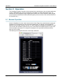
5.3 XML Operation
Custom XML computer applications may be created to monitor and control the SmartStorm Irrigation
Controller. This method does not use a web browser. diagnostics.xml is available for troubleshooting and
system monitoring.
5.3.1 Monitoring
The state of the relays, inputs, and sensors can be monitored by sending a request to port 80 (or port
specified in setup). This can be demonstrated by entering the following URL into the address bar of a
web browser (substituting the IP address as necessary):
http://192.168.1.2/state.xml
The following state.xml page is returned:
<datavalues>
<runMode>0</runMode>
<zone1>0</zone1>
<zone2>0</zone2>
<zone3>0</zone3>
<zone4>0</zone4>
<zone5>0</zone5>
<zone6>0</zone6>
<zone7>0</zone7>
<zone8>0</zone8>
<zone9>0</zone9>
<zone10>0</zone10>
<input1state>1</input1state>
<input2state>1</input2state>
<units>F</units>
<sensor1temp>x.x</sensor1temp>
<waterBudget>100</waterBudget>
<prgmsRunning>0</prgmsRunning>
<serialNumber>SmartStorm Serial Number</serialNumber>
<time>1424951320</time>
</datavalues>
The numbers enclosed by the tags, <tag>, indicate the current state or value monitored by the
SmartStorm. Values for each tag are described in the table below.
XML computer applications will open a TCP/IP socket with the SmartStorm and send a GET command
followed by the state.xml command string
Xytronix Research & Design, Inc.
Page 43
Operation
SmartStorm Irrigation Controller™ Users Manual
XML Tags*
Monitor Values
Control Values
<runMode>
0 = OFF
1 = Automatic
0 = OFF
1 = Automatic
<zoneX>
The amount of time in seconds that the zone has until
it is done running.
0 = Zone OFF
0 = Turn zone OFF
# = Turn zone on for x
minutes
<inputXstate>
0 = Input ON
1 = Input OFF
n/a
<units>
F = Fahrenheit
C = Celsius
n/a
<sensor1temp>
x.x = Indicates that no digital temperature sensor is
attached.
77.3 = Current temperature.
n/a
<waterBudget>
Percent water budget that the SmartStorm is using.
-1 or -2 if a digital input has stopped the program
-3 if low temperature has stopped the program
n/a
<prgmsRunning> 4 bit number converted to decimal to determine which
programs are running.
advanceX = 1
stopX = 1
<serialNumber> 00:00:00:00:00:00, serial number of the SmartStorm.
n/a
<time>
1253030401 = Time displayed in “epoch time” (number n/a
of seconds since January 1, 1970)
* 'X' is replaced by the zone number or input number.
5.3.2 Control
zoneXState commands can be sent to the SmartStorm to control the zones. X is replaced by 1 for Zone
1, 2 for Zone 2, and so forth. The following are a few examples:
Command
Description
state.xml?zone1State=0
Turn Zone 1 OFF
state.xml?zone1State=10
Run Zone 1 for 10 minutes
state.xml?zone2State=0
Turn Zone 2 OFF
state.xml?zone2State=20
Run Zone 2 for 20 minutes
5.3.3 Program Control
advanceX, and stopX commands can be sent to the SmartStorm to control the programs. X is replaced
by 1 for Program A, 2 for Program B, and so forth. The following are a few examples:
Page 44
Command
Description
state.xml?advance1=1
Turn Program A ON or advance to next zone
state.xml?stop1=1
Turn Program A OFF
state.xml?advance2=1
Turn Program B ON or advance to next zone
state.xml?stop2=1
Turn Program B OFF
Xytronix Research & Design, Inc.
SmartStorm Irrigation Controller™ Users Manual
Operation
5.3.4 Set Run Mode
rMode commands can be sent to the SmartStorm to control the programs. The following are a few
examples:
Command
Description
state.xml?rMode=1
Set run mode to Automatic
state.xml?rMode=0
Set run mode to OFF
5.3.5 Password
If the Control Password is enabled on the SmartStorm and the state.xml page is requested through a
browser, the user will be prompted for a password. If the XML request is sent from an XML application,
the HTML request will need to contain the password, encoded as Base64. The following is an HTML
request header without the password:
GET /state.xml?zone1State=10 HTTP/1.1 (Terminated w/ two \r\n.)
The following example adds the password:
GET /state.xml?zone1State=10 HTTP/1.1 (Terminated with \r\n.)
Authorization: Basic bm9uZTp3ZWJyZWxheQ==(Terminated with two \r\n.)
bm9uZTp3ZWJyZWxheQ== is the Base64 encoded version of the user “name:password,”
none:webrelay.
A utility is provided at http://www.controlbyweb.com/encoder to encode the password. Simply type the
password into the website and press 'Encode'.
Xytronix Research & Design, Inc.
Page 45
Appendix A: Restoring Factory Default Settings
SmartStorm Irrigation Controller™ Users Manual
Appendix A: Restoring Factory Default Settings
In the event that the IP address or passwords are forgotten, the SmartStorm Irrigation Controller may be
restored to its original factory default settings.
1. Remove the AC power from the unit.
2. Use a thin, non-conductive object (such as a toothpick) to press and hold the small internal button
located next to the 5-position terminal connector. A tactile feel can be detected as the button is
pressed.
3. While depressing the button, apply power and wait for about 10 seconds before releasing the button.
All settings will be back to the original factory defaults. log.txt and syslog.txt are retained.
4. Refer to Section 3.1 Establishing Communications for Setup to begin reconfiguration of the
device.
Page 46
Xytronix Research & Design, Inc.
SmartStorm Irrigation Controller™ Users Manual
Appendix B: Installing New Firmware
Appendix B: Installing New Firmware
From time to time, updates are made to the SmartStorm Irrigation Controller firmware. The SmartStorm
firmware can be updated in the field. The procedure for updating the firmware is outlined below. Please
note that it is important that this procedure is followed precisely.
Requirements
The firmware update software requires a Windows PC with the .Net framework installed. The .Net
framework is generally installed automatically through Windows update. To install it manually, go to the
following address:
http://www.microsoft.com/downloads/details.aspx?FamilyId=333325FD-AE52-4E35-B531508D977D32A6&displaylang=en
Select the Download button. Once you've downloaded the installation file, double click on the installation
file to install the framework.
Setup
1. Download the bootloader.exe and the new firmware image from the ControlByWeb support team. Only a
SmartStorm image can be installed on a SmartStorm so make sure the correct image is being
downloaded.
2. bootloader.exe will connect to the SmartStorm using default IP address 192.168.1.2, not the address
currently assigned to the SmartStorm. After the update, all settings will be lost and the device will return
to its default IP address of 192.168.1.2.
Configure the PC to the same subnet as the IP address 192.168.1.2, such as 192.168.1.10. For
instructions on doing this see section 3.1 Establishing Communications for Setup.
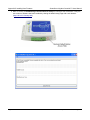
3. Open the bootloader.exe utility on the computer by double clicking on the downloaded file (Figure
Appendix B.1).
4. Within the cbwProgrammer utility programmer, select File, then Open. Specify the firmware image
downloaded from the ControlByWeb™ support team.
Device Upgrade Procedure
Carefully follow the following steps to put the SmartStorm into bootloader mode and perform the upgrade.
Make a note of the current settings. The device will be reset to factory defaults after the upgrade.
1. Remove AC power to the SmartStorm.
2. Using a small, non-conductive tool, press and hold the restore defaults button..
3. While holding the button, apply power to the SmartStorm. The Link and Act lights will flash. Continue to
hold the reset button for the next step.
4. While holding the reset button, press the Upload Firmware button at the bottom of the ControlByWeb™
Programmer window. After the programming process begins, the reset button can be released
5. Programming will take approximately 20-30 seconds, the Link LED will stop flashing and remain lit. The
SmartStorm will be set to factory defaults with an IP address of 192.168.1.2.
Xytronix Research & Design, Inc.
Page 47
Appendix B: Installing New Firmware
SmartStorm Irrigation Controller™ Users Manual
6. Refer to section 3.1 Establishing Communication for Setup to reconfigure the SmartStorm. Verify the
new version of firmware has been installed by viewing the default setup page with a web browser
(http://192.168.1.2/setup.html).
Page 48
Xytronix Research & Design, Inc.
SmartStorm Irrigation Controller™ Users Manual Appendix C: Accessing the SmartStorm Irrigation Controller™
Over the Internet
Appendix C: Accessing the SmartStorm Irrigation
Controller™ Over the Internet
SmartStorm Irrigation Controller™ can be monitored and/or controlled from a remote location over the
Internet. Once the SmartStorm can be accessed on the local network, almost all of the settings required
to provide remote access are in the router and not in the SmartStorm. This guide is not meant to be a
tutorial in router setup, but rather to provide a basic overview of remote access. For specific details, the
user should refer to the instruction manual for the router on the local network. Users not familiar with
basic IP networking should study one or more basic IP networking tutorials before proceeding (many
tutorials are available on the Internet).
IP Addresses
Every device on the Internet is identified by a unique address called an IP (Internet Protocol) address. IP
addresses are somewhat similar to mailing addresses in that they identify the precise logical location of
the device on the Internet. The IP address identifies the global region down to the network and then the
specific device on that network. IP addresses are globally maintained and assigned by an entity called
the Internet Assigned Numbers Authority (IANA). IP addresses consist of four numbers that range from 0
to 255 and are separated by a decimal. For example, 192.168.200.167 is an IP address.
Every device that is “directly” connected to the Internet uses a “public” IP address. The SmartStorm can
be assigned a public IP address for direct connection to the Internet. Typically, a public IP address to
would only be assigned to the SmartStorm when it is the only device on the local network. The IP
address would be obtained from an Internet Service Provider (ISP).
Due to the limited number of public IP addresses, private networks can be set up with “private” IP
addresses. These addresses are used withing a local network and have no global designation, they are
not routed on the Internet. The following address blocks are designated for private networks (where x
represents decimal numbers from 0 to 255): 192.168.x.x, 10.x.x.x, and 172.16.x.x - 172.31.x.x.
A Simple Local Area Network
A small Local Area Network (LAN), can be made up of two or more computers or other devices
connected to an Ethernet switch. Each device on the network is assigned a unique private IP address.
For example, consider a simple network that consists of a computer, a SmartStorm, and a WebRelay™.
In this example, the computer is assigned an IP address of 192.168.1.10, The SmartStorm has the IP
address of 192.168.1.25 and a WebRelay™ has and IP address of 192.168.1.26. A person using the
computer can access the SmartStorm by entering its IP address in the URL line in the browser,
http://192.168.1.25. Similarly, WebRelay™ can be accessed by entering its unique private IP address in
the URL line in the browser, http://192.168.1.26.
Xytronix Research & Design, Inc.
Page 49
Appendix C: Accessing the SmartStorm Irrigation Controller™ Over the Internet
Controller™ Users Manual
SmartStorm Irrigation
A Simple LAN connected to the Internet
The LAN in the example above can be connected to the Internet by adding a router and an Internet
connection. The router has two network connections. It has an Ethernet network connection to the LAN
and another connection to the Internet. Often the Internet connection is called a Wide Area Network
(WAN) connection. Each network connection on the router has an IP address. In our example, the IP
address on the LAN side of the router has an address of 192.168.1.1. The IP address on the WAN side
of the router has an IP address that has been assigned by the Internet Service Provider, such as
266.70.164.97. (This is not a valid IP address because each number cannot be larger than 255 It is used
in this example for illustration purposes only.)
In the example, when a user on the computer needs to access a server on the Internet, the computer
sends the request to the router at 192.168.1.1. The router sends the request to the ISP server on the
Internet. The ISP server does not send the response directly to the computer on the LAN, but to the
router at the IP address of 266.70.164.97. The router then forwards the response to the computer. This
Page 50
Xytronix Research & Design, Inc.
SmartStorm Irrigation Controller™ Users Manual Appendix C: Accessing the SmartStorm Irrigation Controller™
Over the Internet
way, all devices on the LAN share a single public IP address. This is called Network Address Translation
(NAT).
Port Forwarding
The router can be configured to allow outside access to the SmartStorm™. All requests from the Internet
to any device on the local network must use the public IP address (266.70.164.97). With only a single IP
address, TCP ports are used to identify the intended device for the incoming message.
Using the mailing address analogy, the port is similar to a post office box. The IP address specifies the
location, and the port specifies the specific recipient. Port numbers can be set to any number between 1
and 65235. However, many port numbers are reserved for specific applications and should be avoided.
As a general rule, numbers above 8000 are safe to use. All of the ControlByWeb™ products come from
the factory with the HTTP port set to 80, which is the standard port for HTTP. In this example, the
SmartStorm HTTP port will be changed to port 8000 and WebRelay™ port will be changed to 8001.
Once the ports are changed in the two ControlByWeb™ devices, the router must be set up for port
forwarding.
Port forwarding associates the IP address of each local device with an assigned port. In this example,
the address 192.168.1.25 for the SmartStorm would be associated with port 8000. The address
192.168.1.26 for WebRelay™ would be associated with port 8001. The SmartStorm would be accessed
from the Internet by entering the public IP address of the router, plus the port number assigned to the
SmartStorm in the URL window of the browser, http://266.70.164.97:8000. All Internet requests to the
router for port 8000 would be forwarded to SmartStorm. Similarly, all request for port 8001 would be
forwarded to WebRelay.
Note: When an HTTP request comes in to the router without the specific port specified
(http://266.70.164.97), the router will handle this as a port 80 request (default HTTP port). In other
words, http://266.70.164.97 is exactly the same as http://266.70.164.97:80.
Router configuration can vary widely. Some routers have the capability of translating the addresses and
the ports, which would require no port configuration change on the WebRelay. For example, the router
would be configured so that messages sent to http://266.70.164.97:8000 would be forwarded to
http://266.70.164.97:80, which is the default HTTP port.
An example screen shot of a router configuration is given below. This setup allows the two
ControlByWeb™ products in the above example to be accessed remotely from the Internet.
Xytronix Research & Design, Inc.
Page 51
Appendix C: Accessing the SmartStorm Irrigation Controller™ Over the Internet
Controller™ Users Manual
SmartStorm Irrigation
Note: This image is an example of a typical router setup page. Routers will vary.
Accessing Setup Pages
After changing ports, the setup pages are accessed on a local network as described below:
http://(Local IP Address):(Port Number)/setup.html
For example, to access the SmartStorm at the setup page above, the following command would be
used:
http://192.168.1.25:8000/setup.html
To access the ControlByWeb™ units from the Internet, enter the public IP address of the router plus the
port number of the desired device in the following format:
http://(Public IP Address of Router):(Port Number of Device)/setup.html
Using the example above, the following line would be used to access the setup page of the SmartStorm:
http://266.70.164.97:8000/setup.html
Page 52
Xytronix Research & Design, Inc.
SmartStorm Irrigation Controller™ Users Manual
Appendix D: Log Files
Appendix D: Log Files
The SmartStorm logs information to two different log files; log.txt and syslog.txt. Both log files are text
files and are stored in nonvolatile memory; this data will not be lost due to power failure and is also not
cleared when restoring factory defaults. The log files are stored in circular buffers which write from the
beginning of the allocated memory space to the end and then repeat from the beginning (over-writing the
original data). The nonvolatile memory is divided into 4K byte sectors. Each time data gets erased to
make room for new data, a full sector (4K bytes) is erased at one time.
Data Log File – log.txt
This log file is user-configurable under the Logging setup tab, see section 4.6 Logging Tab for more
information. and stores real-world data such as temperatures and events such as zone changes. It can
be up to 512K bytes long and is stored using a comma separated value formatting scheme.
The file is read by requesting the log.txt file from the SmartStorm. For example, using the default IP
address the following command would be used to request the log file:
http://192.168.1.2/log.txt
File Format:
MM/DD/YYYY HH:MM:SS,Input 1,Input 2,Zone 1,Zone 2,...,Zone 10,Temperature,
Source
Date and Time Format:
MM – Month (1-12)
DD – Day (1-31)
YYYY – Year (1970-2106)
HH – Hour in 24 hour time (0-23)
MM – Minutes (0-59)
SS – Seconds (0-59)
Sample File:
Date Time,I1,I2,S1,S2,S3,S4,S5,S6,S7,S8,S9,S10,T,Source
02/24/2015
02/24/2015
02/24/2015
02/24/2015
02/24/2015
14:10:36,0,0,0,0,0,0,0,0,0,0,0,0,075.0,InpAdvCyc:(02)
14:10:36,0,0,0,0,0,0,0,0,0,0,1,0,075.0,MValveON:(01)
14:10:36,0,0,1,0,0,0,0,0,0,0,1,0,075.0,StnON:(MANUAL,01)
14:11:03,0,0,1,0,0,0,0,0,0,0,0,0,075.1,MValveOFF:(01)
14:11:03,0,0,0,0,0,0,0,0,0,0,0,0,075.1,StnOFF:(MANUAL,01)
The file can then be saved using the 'Save As...' option under the 'File' menu of the web browser. If the
TCP port has been changed (not port 80), the port will be required to read the file. For example, using
the default IP address, and port 8000, the log file would be read as follows:
http://192.168.1.2:8000/log.txt
The log.txt file may be erased with the following command:
http://192.168.1.2/log.txt?erase=1
After erasing the file, it might be necessary to refresh the page.
Note: If the Control Password is enabled in the setup pages, the password will be required to access
the log file.
Xytronix Research & Design, Inc.
Page 53
Appendix D: Log Files
SmartStorm Irrigation Controller™ Users Manual
System Log File – syslog.txt
The syslog.txt file records various system events, which can be used for diagnostics and troubleshooting
purposes.
File Format:
MM/DD/YYYY HH:MM:SS, (category to which message applies): (message)
Sample File:
01/02/2015 04:08:13 DEVICE: Power Up.
01/01/2015 00:41:05 DEVICE: Reset factory defaults.
Listed below is a description of messages that a user may see:
Category
DEVICE
CLOCK
NTP
SERVER
REMOTE
SERVER
DHCP
Message
Description
Power Up
Device has been properly powered.
Initialize
Device is ready.
Reset Factory Defaults
Device has been reset to factory defaults.
RTC Reset
Real Time Clock has been reset.
Request Attempt
Device attempting to connect to NTP Server
Failed DNS Lookup
Unable to lookup NTP server name due to an incorrect DNS
setting.
Success
Device successfully connected to NTP Server.
Failed DNS Lookup
Unable to lookup Remote Server due to an incorrect DNS
setting.
Connection Attempt
Started
Connection port with Remote Server has been opened.
Connection Closed
Connection port with the Remote Server has been closed.
Address Acquired
IP address request successful, and IP address assigned.
Lease Renewal
IP address assigned to device was renewed.
MAIN_MCU New Firmware Loaded
New firmware has been loaded to the device.
This file is read by requesting the syslog.txt file. For example, using the default IP address the following
command would be used:
http://192.168.1.2/syslog.txt
Note: The setup user name and password are required to access this file.
If the TCP port has been changed (not port 80), the port will be required to read the file. For example,
using the default IP address, and port 8000, the log file would be read as follows:
http://192.168.1.2:8000/syslog.txt
To erase the file, use:
http://192.168.1.2/syslog.txt?erase=1
Page 54
Xytronix Research & Design, Inc.
SmartStorm Irrigation Controller™ Users Manual
Appendix E: External Server and Remote Services
Appendix E: External Server and Remote Services
Note: The following methods are supported by the SmartStorm; however, Xytronix Research & Design,
Inc. does not provide or support custom third party applications, or external web servers.
Accessing the SmartStorm Irrigation Controller with Custom Software or
Third Party Applications
Custom applications can send commands to the SmartStorm for monitoring and control. The application
interface can be used to provide a custom user interface, access to multiple units in a single screen, and
allow for automation, logging, and other application-specific features.
Using an External Web Server
Rather than accessing the SmartStorm directly from a computer, an external web server can be used.
The term “external” web server is used here to mean a separate web server (such as Apache or IIS) that
is not the web server built into the SmartStorm. In this scenario, users access custom web pages that
reside on the external web server and the external web server communicates with the SmartStorm.
An external web server can integrate multiple ControlByWeb products into a single control page. In other
words, the user may not be aware that he/she is using multiple ControlByWeb™ devices, but rather the
user sees an integrated control page for the entire system. In addition, the use of an external web server
allows programmers to create custom user interfaces that take advantage of the additional resources
typically available on larger web servers, including more memory and various web programming
languages.
There are two approaches that an external server can use to communicate with the SmartStorm and
other ControlByWeb™ devices, Direct Server Control and Remote Services.
Direct Server Control
The first approach is for the external server to create a TCP connection whenever it needs to access the
SmartStorm. In this case, the external server opens the connection, sends commands and/or reads the
device, and closes the connection.
This method is ideal when the web server and all of the SmartStorm devices are on the same network
(without routers between them). In this case, the server can communicate with the SmartStorm devices
directly and securely since data never has to leave the local network.
When the server and a SmartStorm are on different networks, routers must be configured to allow
appropriate access. If a public network is used, such as the Internet, security precautions should be
considered.
Remote Services
The second approach is for the SmartStorm to initiate a connection using the “Remote Services.” The
settings under the Advanced Network tab in the setup pages will enable the SmartStorm to open a
TCP connection with an external server. Once the connection is open, the external server can send
commands and/or read the device. The external server can leave the connection open (so that it never
closes) or close the connection.
“Remote Services” is ideal for installations where the server and a SmartStorm are installed on different
networks. This is especially useful when each SmartStorm is installed on a separate private network. For
example, if the user doesn't control the network connections where the SmartStorm is installed, “Remote
Services” would initiate a TCP connection over the Internet with the control computer. Since the
SmartStorm initiates the connection, the control computer doesn't have to know the IP address of the
SmartStorm. This means that the SmartStorm can be installed using DHCP. In addition, no special
router configuration is required. This makes the network installation of the SmartStorm very simple, and
Xytronix Research & Design, Inc.
Page 55
Appendix E: External Server and Remote Services
SmartStorm Irrigation Controller™ Users Manual
since no incoming ports need to be opened in the router, security is not compromised. See section 4.3
Advanced Network Tab for more information.
The SmartStorm can be configured to establish a connection when triggered by an event, such as a
relay state changing. This is done by setting the Remote Service/SNMP checkbox in the relay and input
setup tabs.
Connection String
With Remote Services enabled, a connection attempt will be made periodically according to the
Connection Interval setting in the Advanced Network setup tab. The Connection String is a userdefined character string configured in the Advanced Network tab.
The connection string is also sent at the same interval once the connection is open. The external server
is responsible for closing the connection when it is done.
Remote Commands
Once the connection is open, the remote server can issue HTTP GET requests to the device for XML
files.
Request about.html:
GET /about.html HTTP/1.1\r\n\r\n
Turn Zone 1 ON for 10 minutes:
GET /state.xml?zone1State=10 HTTP/1.1\r\n\r\n
Page 56
Xytronix Research & Design, Inc.
SmartStorm Irrigation Controller™ Users Manual
Appendix F: Specifications
Appendix F: Specifications
Operating Specifications
Programming:
Number of zones:
Station timing:
Start Time:
Programming Schedule:
Monthly Water Budget::
Shutdown:
Logging:
Easy to use web page setup and operation
Zones can be named, programs are displayed in chart format
10 (two zones can be individually programmed as a master valve
or pump)
4 individual programs (A, B, C, D), 1-minute increments
up to 254 minutes/station, programmable delay between stations
8 for each program
Odd day, even day, day of week, variable day cycle
0 – 100% for each calendar month
With low temperature or rain
Temperature and schedule events are logged to non-volatile memory
Electrical Specifications
Input Voltage:
Input Current:
Zone Load Capacity:
Internal Fuse:
Protection:
Program Storage:
24VAC ±10%, 60Hz
125mA typ (10Mbps), 180mA typ (100Mbps), plus zone valves
Up to two 24VAC, 7VA solenoid valves or one 24VAC, 7VA solenoid
valve plus a master valve or pump start relay
1.5Amp, 3AG (¼ x 1-1/4”)
AC input and each zone output is protected with an internal
MOV (metal oxide varistor) over voltage surge protection device
Nonvolatile memory
Ethernet
10 Base-T or 100 Base-T, 8-pin RJ-45 Ethernet
Network
Ethernet IPv4, Static IP address or DHCP
Supports Web Browser (HTTP) and XML
Remote services – can be controlled and monitored from an external web server
Real-Time Clock
Manual or NTP (Network Time Protocol) setup, NTP Sync configurable for periodic update
Automatic daylight savings adjustment
Battery backup via internal super capacitor, 30 days minimum
Accuracy ±1-minute/month
Removable Connectors:
Zones:
Sensor Input:
14-position, 3.81mm (Phoenix P/N 1803691)
5-position, 3.81mm (Phoenix P/N 1803604)
Connector Specifications:
Type:
Connection wire:
Stripping Length:
Connection capacity:
Conductor minimum:
Conductor maximum:
Conductor Type:
Tightening torque:
Xytronix Research & Design, Inc.
14-position and 5-position, removable, 3.81 mm pitch
Use wire rated for 75ºC (min) for connections to the terminal blocks
7mm
1.5mm2 stranded, 1.5mm2 solid
30AWG (UL/CUL)
14 AWG (UL/CUL)
Copper
0.22 Nm (min), 0.25 Nm (max)
Page 57
Appendix F: Specifications
SmartStorm Irrigation Controller™ Users Manual
Pushbutton & LED Indicators
Pushbutton:
Green:
Yellow:
Ethernet:
Manually select and activate a specific zone (plus pump if enabled)
Power On
Zone 1 thru 10
Green = Linked, Yellow = Activity
Sensor Inputs
Digital Inputs:
Temperature Sensor:
Two, programmable, rain delay or manual operation
Vin Max = +5.0V, Internal pullup = 47K
Vin HI = 2.8V (min), Vin LO =1.0V (max)
Max cable length 50 ft (use relay isolation for longer runs)
Dallas Semiconductor DS18B20 digital 1-wire thermometer
Accuracy: +/-0.5°C (-10°C to +85°C)
Maximum cable length 600 ft (180m)
Environmental
Location:
Operating Temperature:
Storage Temperature:
Humidity:
Indoor use or NEMA-4 protected location
-40ºC to 65ºC (-40ºF to 150ºF)
-40ºC to 85ºC (-40ºF to 185ºF)
5-95%, non-condensing
Mechanical
Mounting:
Material
Size:
Weight:
Wall mount
Polycarbonate plastic
7.56 x 5.06 x 1.54 in. (192.14 x 128.64 x 39.24mm)
not including connector
12.3 oz (348.7 g)
Electromagnetic Compliance
IEC CISPR 22, CISPR 24
FCC 47CFR15 (Class B)
EN55024 ITE Immunity (2010)
EN55022 Emissions (2010)
Page 58
Xytronix Research & Design, Inc.
SmartStorm Irrigation Controller™ Users Manual
Appendix G: Trademark and Copyright Information
Appendix G: Trademark and Copyright Information
This document is Copyright ©2015 by Xytronix Research & Design, Inc. All rights reserved.
X-340™, SmartStorm™, WebRelay™, ControlByWeb™, and Xytronix Research & Design™ are
trademarks of Xytronix Research & Design™, Inc. 2005-2015.
All other trademarks are the property of their respective owners.
All parts of this product and design including but not limited to firmware, hardware design, schematics,
PCB layout, concept, graphics, users manual, etc., are property of Xytronix Research & Design, Inc.
©2005-2015. X-340™ may not be copied or reverse-engineered.
No part of this manual may be reproduced or transmitted in any form or by any means, electronic or
mechanical, including photocopying or scanning, for any purpose other than the personal use by the
purchaser of this product. Xytronix Research & Design, Inc., assumes no responsibility for any errors
that may appear in this document.
Whereas reasonable effort has been made to make the information in this document as useful and
accurate as possible, Xytronix Research & Design, Inc. assumes no responsibility for the application,
usefulness, or completeness of the information contained herein. Under no circumstance will Xytronix
Research & Design, Inc. be responsible or liable for any damages or losses including direct, indirect,
special, incidental, or consequential damages or losses arising from either the use of any information
contained within this manual or the use of any products or services referenced in this manual.
Xytronix Research & Design, Inc. reserves the right to change any product’s features, specifications,
documentation, warranties, fee schedules, and conditions at any time and without notice.
Xytronix Research & Design, Inc.
Page 59
Appendix H: Warranty
SmartStorm Irrigation Controller™ Users Manual
Appendix H: Warranty
This Xytronix Research & Design, Inc. product has a warranty against defects in material and
workmanship for a period of one year from the date of shipment. During the warranty period, Xytronix
Research & Design, Inc. will, at its option, either repair or replace products that prove to be defective.
This warranty is extended to the original purchaser of the equipment only.
For warranty service or repair, the product must be properly packaged, and returned to Xytronix
Research & Design, Inc. The purchaser shall prepay all charges for shipping to Xytronix Research &
Design, Inc., and Xytronix Research & Design, Inc. will pay the shipping charges to return the product to
the purchaser as long as the product is shipped within the United States. If the product is shipped
outside of the United States, the purchaser shall pay all shipping charges, duties, and taxes.
Limitation
The foregoing warranty shall not apply to defects or damage resulting from improper use or misuse,
unauthorized repair, tampering, modification, improper connection, or operation outside the
electrical/environmental specifications for the product. Further, the warranty does not cover Acts of God,
such as fire, flood, hurricanes, and tornadoes. This warranty does not cover damage to property,
equipment, direct, indirect, consequential, or incidental damage (including damage for loss of business
profit, business interruption, loss of data, and the like) arising out of the use or misuse of this product.
UNDER NO CIRCUMSTANCES WILL THE LIABILITY OF XYTRONIX RESEARCH & DESIGN, INC. TO
THE PURCHASER OR ANY OTHER PARTY EXCEED THE ORIGINAL PURCHASE PRICE OF THE
PRODUCT, REGARDLESS OF THE FORM OF THE CLAIM. No other warranty is expressed or implied.
Xytronix Research & Design, Inc. specifically disclaims the implied warranties or merchantability and
fitness for a particular purpose. Some jurisdictions may not allow the exclusion of limitation of liability for
consequential or incidental damage.
Page 60
Xytronix Research & Design, Inc.
SmartStorm Irrigation Controller™ Users Manual
Appendix I: FCC Statement
Appendix I: FCC Statement
This device complies with Part 15 of the FCC Rules. Operation is subject to the following two conditions:
- This device may not cause harmful interference.
- This device must accept any interference received, including interference that may cause undesired
operation.
Warning
This equipment has been tested and found to comply with the limits for a Class B digital device,
pursuant to Part 15 of the FCC Rules. These limits are designed to provide reasonable protection. This
equipment generates, uses and can radiate radio frequency energy and, if not installed and used in
accordance with the instructions, may cause interference to radio communications. There is no
guarantee, however, that interference will not occur in a particular installation. If this equipment does
cause harmful interference to radio or television reception, which can be determined by turning the
equipment off and on, the user is encouraged to try to correct the interference by one or more of the
following measures:
-
Reorient or relocate the receiving antenna.
Increase the separation between the equipment and receiver.
Connect the equipment into a relay on a circuit different from where the receiver is connected.
Consult the dealer or an experienced radio/TV technician for help.
Notice
Changes or modification not expressly approved by the party responsible for compliance could void the
user’s authority to operate the equipment.
Xytronix Research & Design, Inc.
Page 61
Appendix J: Mechanical Dimensions
SmartStorm Irrigation Controller™ Users Manual
Appendix J: Mechanical Dimensions
Page 62
Xytronix Research & Design, Inc.