1
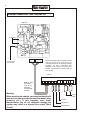
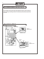
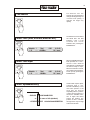
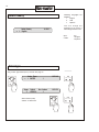
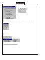
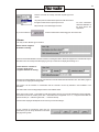
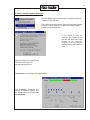
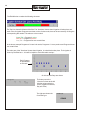
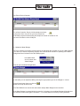
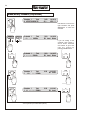
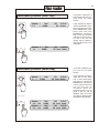
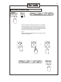
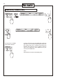
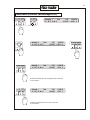
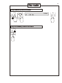
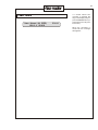
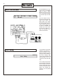
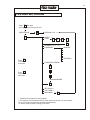
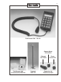
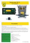
Schedule 1
Total
2 SMTW-F-S-T-T-SS
STEP
DAY
SCHEDULE
STATION
MANUAL
AUTO
(3)
TIME
0:44
3:30
TWC
USER
MANUAL
10:55:40
105% P
WATER
BUDGET
-
CANCEL
ACTIVE/
PASSIVE
+
ENTER
TWO WIRE CONTROLS
1
2
4
9
S
F1
O
F
Rev.3/30NOV00
6
8
L
R?
3
5
7
T
TA
RT
DE
CO
DE
F2
D
E
Table of content:
White section:
System overview
Introduction
Getting started
Controller installation
Remote Access Software
2
3
5
6
19
Green section
Using local controls
Schedule set up
Troubleshooting
49
52
68
Yellow section
Options
Appendix
Equipment photos
Specifications
72
Index
80
74
78
2
System Layout
TWC-50/100/200
PC
Mains
Transformer
Modem (Serial Port)
Optocoupler
24 V AC
Line Termination Box
LTB-100
Phone Outlet***
Note
Rain Sensor
2 wires
Line
Decoder
Solenoid
Valve
Ground
Rod
Pump Alarm
Sensor
Decoder
Sensor
Line
Decoder
The TWC-controller has 3 versions: TWC-50 with a capacity of
50 decoders, TWC-100 with 100 decoders and TWC-200 with
200 decoders. All are available with the same capacity and a
built-in modem (indicated by the extension C).
***Only TWC-XX0-C which has built-in modem.
Solenoid
Valve
Note: Optional LTB-210 with provision for 5 field lines.
3
Introduction
The 2-wire or decoder system uses one 2-wire line that runs from the controller to the nearest valve, from
thereon to the next valve, etc. With all the valves "sitting" on the same line, a decoder is needed at each
valve to interpret signals from the controller and to turn on or off the attached valve. The 2-wire line carries
both signalling and power to operate the valve and is continuously powered.
The TUCOR 2-wire technology has been used for golf applications worldwide since 1987 and
approximately 2000 systems are now installed and still in operation with a total of half a million decoder
buried in the ground.
Main features of TUCOR 2-wire Technology:
* Wire costs are lower.
* The system may be expanded from any point of the 2-wire, just by splicing in further 2-wire
paths.
* Power requirement 10 times lower than conventional technology.
* The low power directly translates into longer wire runs.
* Electronic protection against corrosion of wires.
* Two-way communication on 2-wire allows usage of Field Acces Unit and Sensor Decoder (see
options).
4
Options
LTB-210
Line Termination Box. If your field installation needs more than 2 individual
cables from the controller, you may use this box which has provisions for 5
cables.
PD-100
Pump Decoder has a set of relay contacts instead of the ususal power output.
Both make- and break contacts are employed. The decoder is for dry
environments only.
FA-100
Field Access Unit, plugs directly into the 2-wire and operates any valve
connected to the system.
SD-100
Sensor Decoder may be installed anywhere on the 2-wire and will read and
transmit to the controller the status of a sensor being it a switch (on/off) or an
analog sensor (flow, temperature, etc.)
Help/support
Call TUCOR (724) 935-6850 or use our web site, www.tucor.com
Registration
Each controller must be registered with TUCOR to ensure warranty. A registration card is
provided.
Warranty
TUCOR has a one year warranty on all products.
5
Getting started
Your TWC-XX control pagckage comprises the following:
- TWC-XX Controller with built-in items:
-Program Module
-Memory Module
-(Extra Memory Module (TWC-100 only))
-(Modem (TWC-XX-C only))
- LTB-100 Line Termination Box
- Transformer 110/24 VAC
- TWC-RAS Software on CD-ROM
- Manual
- MOP-1, Modem Cable 1 ft.
- MOP-2, Modem Cable 6 ft.
-OC-200, Optocoupler
TWC-RAS program
This software package installs on a PC and allows you to communicate with the controller,
either via modems remotely or directly using the supplied cable. The TWC can also be
operated directly from the panel, but it is convenient to use the TWC-RAS when working
with larger installations because it is easier and faster to input data this way.
6
External Connections, TWC-100/TWC-50
PSM-100
2 fuses 2A T
6 5 4
24 V AC from
Transformer
1 2 3
The Line termination Box should be located
near the ground rod and not next to the
controller because of the lightning damage
possibility. The box is waterproof and
designed for an outdoor mount. The cable
between the controller and the box may be
up to 100 feet.
LTB-100
Multipart cable
with 6 wires
(max. dia. .4")
Preferably
multistranded
(Flexible)
1 2 3 4 5 6 7 8 9 10
Warning:
When mounting the cabinet, care must be taken that it
does not become grounded through the mount (steel
structure etc.). If this happens, even small
thunderstorms that do not otherwise damage the
system, may result in a shorted Line output (Short
Circuit).
2-wire
paths
Ground
Rain Sensor
Pump Sensor
7
Internal Connections, TWC-XX
Master Control Module
MCM-XX
Display Module LD-100
Data Module
MM-XX
(Data Module
MM-100)
Program Module
TM-XX
Power Supply Module
PSM-100
Modem port
ON/OFF switch
TWC-XX-C, installing the phone cable
MOP-0
Modem
Display Module LD-100
Clip
Clip
Power Supply Module
PSM-100
Clip
Master Control Module
MCM-100
ON/OFF switch
Modem port
Phone
Cord
To eliminate disturbances from
noise, it is essential to attach the
phone cord to the 3 plastic clips.
8
The Flowmaster Models, TWC-200/-100/-50
The 3 Flowmaster models, TWC-50, TWC-100 and TWC-200 consists of a base unit and some
plug-in modules. It is the plug-in modules that determines the actual model. The following 3
pictures shows which modules goes with which model, what they look like and where they should
be socketed.
Plug-in Modules, TWC-50
MCM-100
(on door panel)
MM-100
Memory Module
Program
version
1009
TM-50
Program Module
9
Plug-in Modules, TWC-100
MCM-100
(on door panel)
MM-100
Memory Module
MM-100
Memory Module
Program
version
1010
TM-100
Program Module
Plug-in Modules, TWC-200
MCM-200
(on door panel)
MM-200
Memory Module
Program
version
1018
TM-200
10
DIP-Switch settings
Switch No.
Function
Open
Closed
6
Serial Port
Modem
Direct connection
7
Pump Sensor
Normally Open (NO)
Normally Closed (NC)
8
Rain Sensor
Normally Open (NO)
Normally Closed (NC)
9
Max. valves/STEP
5
10
10
Valve Types
RB 1&2 valves/Decoder
1-5 variable
11
Number of days
15
14
12
Alphabet
full
1234567890SGLDB
Do not change switches with power on!
By default all switches are open from factory.
6
Serial Port
Leave this switch open: In this position it is also possible to
upload/download data and schedules with a PC.
10
Valve Types
When the switch is open, the default switch code is used, which will
work with most valves (see page 14 ).
11
Number of days
Unless an every third day mode of operation is needed, it is
recommended to close the switch for 14-day operation.
12
Alphabet
If you plan to use the Field Access Unit, you have only a limited choice
of characters when naming the valves. If the switch is closed only valid
characters can be selected.
11
Installation (of Data)
The display normally shows information for irrigation/scheduling. Before any
operation/scheduling can be done,it is necessary to enter Installation Data (decoders,
pumps, sensors etc.) and to set the date and time.
The Menu Tree below shows how to get to the various items. To enter the menu system,
press both ENTER and CANCEL buttons simultaneously.
Menu Tree
1. Remote Connection
2. Installation
3. Setting Date/Time
(1. Valve Types)***
2. Decoders
3. Pump
4. Sensors
5. Switch Settings
6. Erase All
7. Select Country
8. Return
1. English
2. USA
3.
4.
5.
6.
7. Spanish
8.
9. Return
Main Menu
1. Test of Line Decoders
2. Short Finding
3. Ground Fault Test
4. Return
4. Test
5. Return
*** Only if Valve Type switch
(D10)
is closed
+
Schedule 1
Total
12 M--T--S--W--S
2:07
(1)22:00
14:36:05
125% A
CANCEL
ENTER
Press both ENTERand CANCEL-button to
go to Main Menu
12
The TWC Front Panel
Schedule 1
Total
2 SMTW-F-S-T-T-SS
The 5 buttons are
used when
writing schedules
STEP
SCHEDULE
The 4 buttons are
used for manual
operations and to
start irrigation.
MANUAL
DAY
STATION
AUTO
(3)
TIME
0:44
3:30
10:55:40
105% P
WATER
BUDGET
-
CANCEL
TWO WIRE CONTROL
The number indicates
the size of the controller
(50, 100 or 200
decoders
ACTIVE/
PASSIVE
+
ENTER
The display gives
an overview of the
status and is used
when installing
data and writing
schedules
This rotating knob
(the selector) is
used for variable
input like minutes
and for selecting
from menus.
These 2 buttons
are used to
confirm or cancel
selections.
13
The Selector has two
speeds. If it is turned slowly it
changes the target slowly. If it
is turned more quickly, it
changes the target very
rapidly.
The Selector
-
CANCEL
+
ENTER
Select Field (STEP, STATION, MINUTES etc.)
-
CANCEL
+
ENTER
Schedule 1
Total
1 B1
----- >000Min<
0:00
14:18:40
OK Insert
Select Field Input
-
CANCEL
+
ENTER
Schedule 1
Total
1 B1
----- ®008Min¬
0:00
14:18:44
OK Insert
Select alphanumerically
-
CANCEL
+
ENTER
...BLSGD
The Selector is used to select
the actual field. The field
between > and < is the
selected one. Finish
selection with pressing the
ENTER-button.
1234567890BLSGD
or
(in case of full alphabet):
..OPQRSTUVXYZ 1234567890ABCDEFGH
When the ENTER-button has
been pressed, the > and <
turn into ® and ¬ which are
now blinking to indicate that
the field is ready for input.
When the Selector is turned,
the content of the field varies.
Finish input by pressing the
ENTER-button.
Certain fields require alphanumerical input (f. inst.
Decoder installation). In this
case each position in the
field may be entered
separately. When a position
is active and the selector is
turned, the available selection of digits and letters
passes the position. The
position is like a "window"
through which only one digit
at a time can be seen.
14
Following Languages are
available:
1
English
2
USA
7
Spanish
Select Country
Select Country
-> 1. English
This will change the
language for all menu's. It
also changes the flow units:
14:16:11
m/h:
1. English
7. Spanish
Gpm:
2. USA
Valve Types
Only if Valve Type Switch (D10) is closed. See page 10.
-
CANCEL
+
Valve Types
-> 1. 59F350
-
13:51:48
CANCEL
1
+
ENTER
ENTER
V.type Switch
No. of valves
1
1. ®59F350¬
13:51:53
-
-
+
Select Switch (code)
and No. of valves with:
CANCEL
CANCEL
+
ENTER
ENTER
15
Decoders
-
Decoders
-> 1. --
13:51:58
1
-
ENTER
0
13:52:03
Address Booster
0
OK Finish
Name Type
>< 1
-
CANCEL
+
-
+
+
+
CANCEL
CANCEL
Select names with up to 6 characters,
and then select:
Type
Address
Booster (2-10)
OK (Select Finish when
you have installed
the last Decoder)
ENTER
ENTER
Name Type
B12345 1
13:52:03
Address Booster
60170
>Y< OK Finish
Pump
Pump
1.Master
Switch
4FFA20
1.Master 4FFA20
2.Booster 4FFA20
Address
® 284¬
284
286
14:15:21
14:15:21
CANCEL
ENTER
All valves that have a number
for the Booster will run that
booster pump when they are
active. (See below.)
The Switch on the Pump
Relay corresponds with the
following addresses:
1
284
2
286
3
287
4
292
5
293
6
295
Pumps no. 2-10 are
permanently assigned as
Booster Pumps.
16
Sensors
Rain Sensor
Pump Sensor
Active ® Passive¬
14:16:06
Remember to set Sensor
contact mode on Switch D8
for Rain Sensor and D7 for
Pump Sensor. (See DIPswitches on page 10).
A Rain Sensor which gives a
contact opening when it
rains, should be installed as:
Normally Closed (NC).
Flow Sensor (Sensor Decoder)
If a Sensor Decoder is
connected to the system it
must be set up with the Flow
Sensor wizard (see page
31)
Schedule 1
Total
2:07
L13
16 Min Remaining 1:24
14:36:10
8.1Gpm A
The flow will only be shown
when the controller is in
AUTO or in MANUAL mode.
The flow will then be
indicated instead of the
WATER BUDGET.
The measurements from the
Flow Sensor is stored in the
monitoring file.
Flow Sensor, Flow Definition
The Sensor Decoder may be programmed to accommodate 2 different types of sensors: Digital
(pulse output) and analog (4-20 mA).
For all the sensors it is necessary only to give a flow and the corresponding output from the sensor.
This establishes the conversion ratio used by the program to calculate the flow. It is recommended
however to use the max. flow because this determines which of the two pulse types to select. The
resolution is given as soon as the type is selected.
17
Flow Sensor, Digital type
The Digital divides in two types depending on the pulse rate. For high pulse rates the
number of pulses in 10 seconds are counted. For low pulse rates the time between the
pulses in ms is measured.
Pulse/10s.
This type is used for sensors with high pulse rates. Fastest rate is 5 ms/pulse (200 Hz)
with a pulse/pause ratio of 2.5 ms/2.5 ms. This allows up to 2000 pulses to be counted.
At the highest pulse rate (5-10 ms) some pulses might be lost resulting in a reading 10
% too low.
ms/pulse.
This type is used for sensors with low pulse rates. The shortest time that can be
measured is 100 ms with a pulse/pause ratio of 50 ms/50 ms. The longest time is 655
sec's.
Example: A sensor has max
flow of 60 Gpm and at that
flow outputs 78.4 Hz. 78.4 Hz
equals 12.7 ms per pulse.
The Sensor Decoder should
be set up for Pulse/10s. 78.4
Hz (pulses per second)
equals 784 pulses in 10
seconds.
mA.
This type is used for sensors which gives a 4-20 mA signal. The resolution is 200 steps.
Connecting an Analog Sensor
Line
Sensor
blue
blue
red
current
black
Sensor
Decoder
green/yellow
Ground Rod
The Sensor Decoder is
supplying the power for the
sensor on the red wire
(arrow shows current
direction). The current is
returned from the sensor on
the black wire.
The Sensor Decoder is in
direct contact with the line
and the potential of the
black wire is -20 V with
respect to ground. The
sensor must therefore be
isolated from the
surroundings (Potential
free).
18
Erase All
OK to Erase All Data?
-> Use ´--´to Cancel
-
16:03:42
Setting Date/Time
+
CANCEL
+
ENTER
CANCEL
-
-
CANCEL
ENTER
1. Installation
--> 2. Setting Date/Time
+
ENTER
®1991¬03--29 12:31:40
Friday(4)
for
+
12:31:35
CANCEL
ENTER
+
CANCEL
-
12:31:45
Year
Month
Date
Hour
Minute
Seconds
Finish with selecting from Main menu: 4. Return
After setting Date/Time you must turn off the
controller and on again to set the monitoring
clock.
ENTER
19
Operators Manual
TWC Remote Access System Software
Contents:
Page
A. About the Tucor TWC-RAS Program………………………………
B. Installing and operating the TWC-RAS…………………………..
C. Getting Started…………………………………………………….
Modem
Setup the Telephone Book
Communications Log
3
4
9
D. Setup Controller/Installation Data……………………………………
12
Collect Data
Edit Installation Data
Transfer Installation Data
Get/Set Controller Time
E. Setup Controller/Irrigation Schedules..............................................
Collect Data
Edit Irrigation Schedules
Transfer Irrigation Schedules
24
F. Connecting…………………………………………………………
29
Call the Controller
Update of Water Budget
G. Working with the Data……………………………………………
Backup/Restore
Print Functions
Monitoring Data
31
Appendix A. Data files……………………………………………….
37
20
A. About the TWC-RAS Program
The system consists of the TWC-RAS program and the controller installed at the remote site.
The TWC-RAS program is a Windows 95/98 program, and it allows Remote Access of the Tucor
family of controllers, the TWC-50, the TWC-100, the TWC-200, the COM-25, and the COM-50.
The program is set up to store information about the Modem and the COM port used by the system.
To connect the operator simply clicks on the site information, and the program will establish the
connection to the remote site.
Once connection has been established a picture of the remote controller will appear on the screen,
and operation is made by clicking the push-buttons of the controller with the mouse. The picture of
the controller is constantly updated to reflect the real appearance of the remote controller, to the
extent that the text of the controller display is pictured on the screen of the PC, and the pictures of
the push-buttons of the controller blink exactly as the buttons on the remote controller.
The TWC-RAS program also allows you to Enter/Edit Installation Data and
Irrigation Schedules off-line and transfer the Data to the Controller.
We hope that you will find the program relatively easy to operate.
Supplied by
Tucor Inc.
518 Wallace Road
Wexford
PA 15090-8642
Phone: 724-935-6850
Fax:
724-935-8233
e-mail: [email protected]
www: http://www.tucor.com
B. Installing the TWC-RAS:
The Tucor TWC Remote Access Software package has to be installed on the Harddisk of your PC.
Approx. 10 Mb free Harddisk space is required.
To Install:
- Insert Distribution CD ROM
- From program manager RUN E:SETUP.EXE
(Your CD ROM drive name may not be "E" !)
The installation program will lead you through a number of windows and will end by copying the files
from the CD-ROM to the Hard Drive
21
22
The installation
program will suggest
that the Software is to
be installed on the "C:"
Harddisk in the
"\Program Files\Tucor
RMS" directory.
Naturally you can
change these
parameters during the
installation.
When you have
entered the information
requested by the
installation program
the files will be copied
to your Hard Drive.
And you will get this
"Setup Complete"
window.
Note: The TWC-RAS
software requires the
"TCP/IP" protocol to
communicate between
the various programs in
the package and it is
typically installed on
your PC already when
an Internet Service
Copnnection or a Local
Area Network is
configured. Should this
not be the case, you
will be guided through
the installation. The
Windows CD-ROM will
be required for this.
23
Start the TWC-RAS Program
To start the program, double-click the icon.
or
use the Windows Explorer to go to the RAS folder and double click the
Turf.exe program
The program and the related subprograms will now start loading…..
The main Menu is shown on the top Line and consists of five main Functions
Functions:
- File
- Irrigation Schedules
- Connect
- Setup
- Help
24
The TWC-RAS program actually consists of four separate programs:
The Main program (Turf.exe)
The communications program
(Turs_server.exe)
To exit the TWC-RAS program you may use
The three “server” programs may be left running to
ensure a faster start-up. If you need to close them,
use the mouse and point to each one and right click
and then select Exit or Quit.
Tucor Control
Database Server
Or
Or
Tucor Control
Server
25
C. Getting Started
You need to set up a few parameters prior to making the first connection to
the remote controller.
1. Setup the Modem
The program uses the Windows Modem setup feature. To install the Modem under Windows
95/98 please refer to your Windows and/or Modem Manual. In most cases
the Plug-and-Play installation of new hardware should work well. If you click the Modem Setup
you will be taken to the Modem Properties
window:
26
2. Setup the Telephone Book
Select the "Open Phone Book" function
in the File menu and the Telephone List
will be displayed:
The Phone Book allows you to enter data for the site, i.e. you can enter Site Name and Telephone
Number.
If you have a direct connection to the controller (Serial Cable with Optocoupler) you
must enter the COM-port in the phone number field.
If you are using a Modem/telephone line to connect to the controller you enter
the phone number here.
If you have to dial through a switch-board you will probably have to enter a prefix
(such as 0 or 9). The prefix should be followed by a "," or a "w". The "," will give a pause of 1
second whereas the "w" will force the Modem to wait until it gets a dial
tone before dialing the next digits. (Examples: 0,8123422 or 0w8123422)
27
3. Setup Communications Log
These functions are mostly of interest in case of communication problems.
They will show all data transmissions (commands to/from theModem) to allow trouble shooting,
mostly during setup of your system. You will not need to be concerned about this once your system
is properly setup.
D. Setup Controller/Installation Data
The TWC-RAS program can be used to program or edit the Installation Data in the Controller.
This is done in three steps (you should take care to go through the process by following the steps
carefully):
1. Collect Data
When this function is activated the
program will dial up the Controller
and retrieve the Installation Data
and the Irrigation Schedules.
Before the call to the Site is made you will be asked if you want to make the call:
28
You are asked to confirm that
you want to make the call,
because the Data that you
collect from the Site will
replace the Data that is
currently stored in the PC.
If you confirm ("Yes") the call will start and during the collection this message will be displayed:
2. Edit Installation
This will open the "Edit Installation Wizzard"
29
First you must indicate the type of controller:
If you are uncertain about the
Controller Type, you can get
the information if your connect
to the Controller on Site via
the direct connection feature.
The top bar displays the
controller type and the onboard software version:
When you have entered the
data for the controller type,
simply press "Next" and you
will be taken to the Valve
Type Window.
For details about the valve
types please refer to the
Controller Operation Manual.
To move on press "Next" to
enter the information about
the Decoders.
30
The table allows you to enter
Name of decoder (Valve), the
address of the decoder, the type
of valve connected to the
Decoder, and a description of
the valve.
(The description wil not be
transferred to the controller.)
When all decoders have been
entered, you can move on to
the Pump decoder definition by
pressing "Next".
Now you can move to the final
step in the "Installation Setiup
Wizzard" by pressing "Next"
31
When you press “Done” the setup wizard will close.
Flowmeter/Sensor Decoder.
If a flowmeter/sensor Decoder is connected to th econtrolle, you need to set up the sensor decoder.
Go to File, Edit Installation, and Flow Sensors
32
Now you have to key in the
information needed to set
up the flow sensor.
Sensor Decoder
The address of the Sensor Decoder is printed on the decoder label.
Calibration Data
This information is needed to enable the Controller to convert the measurement into GPM.
Here we have defined that 784 pulses counted by the sensor over a 10 second period correspond
to 60 GPM.
The actual numbers depends on the flow meter and the pipe size.
Different types of flow meters can bu used and you can set up the sensor decoder to measure in
various ways:
33
Pulse/10 seconds are mostly used with impeller type flow
meters.
ms/pulse (milli-seconds between pulses is used with sensors
that give a small number of pulses per second.
MA (4-20 mA) is an industrial type of sensor.
If you check this box
For more information
about the calibration of
the Flow Sensor see
appendix A.
all flow measurements will be logged in the monitor file.
Alarms
You may set two different types of alarms:
Alarm when an Irrigation
Schedule is running:
If the flow exceeds 50 GPM for more than 2 minutes, we will get an alarm. When this happens the controller will stop all
decoders in the current step and call the pager (phone) 712 223 1221 to display the message 1111.
Alarm when the controller is
in “Auto” mode, but no
Irrigation Schedule is running:
If the flow exceeds 5 GPM for more than 2 minutes the Controller will activate the decoder “MV” and call the pager at
712 223 1221 to display the message 0000.
The “action” can be “Activate” or “Deactivate” and the “decoder” can be any decoder in the installation or all
decoders.
The “Alarm-leak” function will typically be used to close a Master Valve.
Note: The function Call #... Is intended for used with a paging service. The controller will dial the number indicated,
and transmit a series of number plus # and *. Characters are not supported. A “w” or “,” may be inserted after the
phone number (”w” = wait for ting tone and “,” = wait one second).
The format for the pager call depends on the service you are subscribing to.
If your controller is connected to more than one
Flow sensor you can set up the others in the same
way by pressing “Next”.
34
When you have defines all Flow Sensors, press “Done” and the following window
will appear:
Necessary to get
flow measurements
in the logviewer
This window allows you to sum the measurements from all sensors and set up the total flow to trigger alarms and log
the measurements to the monitor file in the same way as for the individual flows.
When you press”Finish” the data setup for the sensor decoders will be stored in the data file on the PC.
For more details on the Flow Sensor please refer to the installation section of this manual.
Flow measurements in the Monitor file
Measurements from the Sensor Decoders are used in two different ways:
As an alarm trigger, i.e. if a certain event happens the controller will react in a certain way. (Refer to the
previous pages)
As a means of monitoring the system, i.e. monitoring the water flow
The monitoring is used as follows:
The controller stores in memory all events (e.g. start a Decoder, stop a Decoder,
get a measurement from a flow sensor)
The flow measurements made by a
specific Flow sensor is
stored in the monitor
file only if you check
this box
35
This is useful if you have several water sources and you want to keep track of the flow rates from each water source.
The measurements are stored in the monitor file and can be seen in the “raw” monitor data. If you use the “Extract and
View” can be found in the “Show Data” function.
If you want to use the flow
measurements to calculate the
water consumption, you must
check this box
Using this allows you to monitor the sum of several flow meters (in the above example we have3 flow meters installed
but we only want to sum number 2 and 3).
The total, as defined above, is shown in the display of the controller and is also stored in the Monitor file, where it is
used to calculate the water consumption. Can be viewed in “Extract and view” using the “Show Overview” function
(Refer to page xx Monitoring Data for more details).
3. Transfer of Installation Data
When you have edited the Installation Data and the Irrigation Schedules you can
transfer the Data to the Controller.
Before the actual transfer of Data
from the PC to the chosen Site you
will be asked if you really want to
proceed.
If you accept to transfer Data, the
program will call the Controller
and automatically transfer Data.
On completion of the transfer an
automatic disconnection will be made.
The Controller must be in a state where it is
not Irrigating or waiting to automatically
start Irrigation ("Auto Mode") in order to
transfer and update Installation Data.
If the Controller is not ready to accept the
update of Installation Data an error
Message will appear:
If this Message appears you must connect to the Controller by
selecting the Connect function and change the Controller (i.e. Stop
Irrigation or disable "Auto" mode).
36
4. Set Controller Time
The Controller runs on its
built-in clock and it is
necessary to verify that the
time and date used by the
controller are correct.
You start the procedure by using “Get Controller
Time”. This will establish a connection to the
controller and retrieve the date and time of the
controller.
If you need to change this you enter the correct data
in the section “Set controller Time” and when you
press “Send time to Controller” a connection will be
made and the date and time transferred to the
controller.
Note: The time and date can be corrected even if the
controller is in “Auto” mode and even if one or more
schedules are in fact irrigating. If you change the time
while irrigation is taking place the running
Schedule(s) will continue unchanged, so you may
want to take the controller out of “Auto”
mode prior to changing the date and time.
37
E. Setup Controller/Irrigation Schedules
The TWC-RAS program can be used to change the Irrigation
Programs in the controller.
Three steps are used to retrieve, edit and transfer the Irrigation
Programs to the Controller. First Step is to Get the Irrigation
Programs from the Controller
If you decide to start the
collection, the program will call
the Site and retrieve the Data
related to the Irrigation
Programs, and you will see a
message during the transfer of
Data:
When the Data has succesfully been
retrieved, the Program will
automatically disconnect.
Second Step is the editing of the Irrigation Data.
The FlowMaster Controllers can
operate 5 Irrigation Programs, and
the editing can be made in the Edit
Irr. Schedules::
38
The Edit Window contains the following elements:
The Top Line shows the Name of the Site. The "Overview" shows when Irrigation will take place, and
each of the 5 Irrigation Programs are shown on the 5 indes cards, that can be accessed by clicking the
corresponding tab number. The tabs are colour-coded:
Green Tab = Program is active
Red Tab = Program is passive
Grey Tab = Program does not contain Data
In the above example Programs 2 & 3 are both active, Programs 1 & 4 are passive and Program 5 does
not contain Data.
The main part of the "Overview" shows when Irrigation is scheduled to take place. The Irrigation is
shown by the Blue bars.....this will be helpful to avoid Schedule overlap.:
Each Program
is represented
on this axis
On this axis the Days are shown
The lower part of the
"Overview" shows at the left
side the values under the
cursor (Irrigation Schedule,
Day and Time).
The right part shows the
Controller type.
39
and the bottom holds the functions:
Zoom: If you place the Cursor in the display of Schedules and hold down the right mouse button you
can "draw" a rectangle, and when you release the mouse button, the time scale will be Zoomed In. To
get back to the full display you click the Zoom Out button.
Grid: This will toggle a grid on/off.
When you want to Edit an Irrigation Schedule you click the relevant Tab:
In this Window you can enter Data about Mode (Active/Passive/Link), Days of Irrigation, up to 6 start
Times and Water Budget (0 to 250 %). For full details of the Irrigation Schedules, please refer to the
Controller Manual.
When you have edited all Irrigation Schedules, click
40
You can now transfer the
Irrigation Schedules to the
Controller:
Before the actual transfer
starts, you will be asked if
you really want to transfer
Data to the Site. When the
transfer takes place the Data
will overwrite the Irrigation
Schedules already stores in
the Controller.
F. Connecting
1. Call a Controller:
When you select the Connect function
41
the Phone Book will appear:
To call the Controller: Simply click the telephone picture:
in the Call column. As soon as you have clicked, the
TWC-RAS program will start dialing the telephone number of the Site or use
the serial connection of the COM port.
2. Update the Water Budget
All Tucor Irrigation Controllers include functions for adjusting daily irrigation by use of a Water Budget
(0 to 250 %). In order to adjust the controller in the Phone Book a functin for updating of the Water
Budget has been included in the TWC-RAS program.
In the Main Menu
click "Connect" and
"Water Budget"
This will open the Water Budget table:
In this table you can adjust the WB by entering the appropriate figure in the "Budget %" column.
Once this has been done you click the
button in the top left had corner.
The TWC-RAS will now call the site and transfer todays Water Budget to the controller.
If the Water Budget is updated while the controller is irrigating, the new Water Budget will be effective
on execution of the next Irrigation Schedule, i. e. it will not effect the currenely running Schedule.
42
Should a call not be successfull the program will stop and display an error message:
This indicates that the phone line is busy
This indicates that the remote Controller
does not respond, possibly because the
Controller has been switched off (Power
Failure).
When you have clicked OK in any of these messages, the box will disappear. You can then later try to
connect manually and if you can get contact you can set the Water Budget by using the Controller
functions.
G. Working with the Data
1. Backup/Restore Data
In the Setup Menu you select
the function Tools to see the
Backup and Restore functions
When you activate the Backup
function you will be prompted to
insert a Floppy Disk in drive A.
And after the backup is performed:
43
The backup function copies the file TWC.LDB which holds the Installation Data and Irrigation Schedules (i.e. All the
data required by the controller).On the floppy disk you will see two files:
Twc.lbk is the data file
Restore.bat is a program that
will allow you to restore the data
from the Floppy Disk (double
click the restore.bat).
2. Print Functions
To print the Installation Data you must access the function Print Inst. Data
To print the IRRIGATION Schedules you must access the function Print Irr. Schedules
44
3. Monitoring Data
The controller stores information about activities, such as activation/de-activation of the valves. The monitoring
data can be retrieved and viewed in different ways.
To work with the Monitoring Data you must use the function Monitoring Data:
Extract and View Monitoring Data
The Extract and View function will also ask if you want to connect to the controller and collect
Monitoring Data. Note: For this to run properly you need Excel 7 or later and Windows 98
or later.
Having answered this question the data will be extracted and the TWC-RAS program will now
look for the spreadsheet program Excel. If Excel is found to be installed on your PC the
spreadsheet program will be started and the Monitoring data will automatically be imported
into Excel. You will see a screen like this:
45
The two functions above (Show data and Show overview) will open two different ways of viewing the Monitoring
data.
Show data: Displays the “raw” data
test
test
test
test
test
test
test
Direct
Direct
Direct
Direct
Direct
Direct
Direct
20000327
20000327
20000327
20000327
20000327
20000327
20000327
013200
013200
013200
013200
013200
013200
013200
L2
L3
L4
L5
L6
L7
L8
D
D
D
D
D
D
D
Stopped
Stopped
Stopped
Stopped
Started
Started
Started
As you can see this is very similar to the comma delimited file you get from the Extract Mon. Data function.
The software remembers the last time you extracted data and it only works with the latest data set which is added
to the old data.
Of course you can use the raw data like any other spreadsheet, i.e. you can work with the data by sorting, filtering,
summing, and so on.
Show overview: Displays Data by steps
As you can see the overview gives details of start/stop time for each step and if you have a Flowmeter/Sensor
decoder installed, it will also give you the water consumption per step and per day….
The overview is calculated from the raw data (Show Data)
View Monitoring Data
The View function performs the same function as the Extract and View function but it does not extract new data…. It
will open the Excel spreadsheet for viewing.
46
Extract Mon. Data (Extract Monitoring Data) will ask you if you want to connect to th econtroller to collect
monitoring data:
If you answer Yes to the question the connection to the
controller will be established and monitoring data will
be collected from the Controller and you will be asked to
specify the data you want to extract:
Specify the date interval
Specify the data you want
to see. Typically all.
You can sort by Account, Site Name
and date
The data will be extracted to a file and
you can specify the location and name
of the extraction file.
Select if you want to append to an
existing file or you wasnt to replace
data (overwrite).
The extraction file created by
the above is a comme
delimited text file which
looks like this:
The extraction file may be
imported into your favorite
spreadsheet or you may
simply view it in a text editor
(e.g. Notepad).
47
Annex: Main Files
The TWC-RAS needs/creates the following main Files:
Turf.exe
Ctrlserv.exe
Odbcserv.exe
Turf_ser.exe
Flowsense.exe
Main Program
Server Program
Database control Program
Server Program
Flow Sensor setup Program
The above files are all loaded into memory when you start "Turf.exe"
twc.ldb
Monitor.ldb
Setup file
Monitoring data file
Turf.cfg
Configuration File, stores the setup of windows sizes,
and location.
Helpfile (about the TWC-RAS program)
Helpfile (About operating the controller)
Turf.hlp
Twc.hlp
During operation the program creates some "Log-files":
Connect.log
SQL.log
Turf.ser.log
Turf.log
Show the calls (connections) made from the PC
Show details about how the database has been called
Show details about the communication (modem data)
Information from the turf program
The 3 last files are cleared whenever the TWC-RAS program is started,
and the Log files are intended for trouble shooting only.
Software version: 1.14
48
This page is intentionally blank
49
Irrigation Schedules
The Flowmaster can store 5 (TWC-200: 10) irrigation schedules. Each schedule is identified by a
number as follows:
Schedule 1
Schedule 2
Schedule 3
Schedule 4
Schedule 5
.
(Schedule 10)
Each Schedule
consists of:
1-60 STEPS (Zones)
(TWC-200 has 100 STEPS)
defined by step number,
Decoders (Valves) and
Run time.
DAYS when irrigation shall
take place.
During the installation the
calendar is set to either
14 or 15 days cycle.
Each Schedule can start
automatically up to 6
TIME's per day.
WATERBUDGET may be
set from 0-250 %. This
adjusts the run time of all
steps in a Schedule.
A schedule can be set to
either ACTIVE or PASSIVE.
When in AUTO only active
schedules will start. For
L (Link) see page 13.
Schedule 1
Total
2 SMTW-F-S-T-T-SS
STEP
DAY
(3)
TIME
0:44
3:30
WATER
BUDGET
10:55:40
105% P
ACTIVE/
PASSIVE
50
Steps
Each step contains Decoders (Valves) and Run Time. The maximum number of
valves running at the same time is 10 valves (COM-50: 5 valves only). This means that
you may include up to 10 (5) valves in each step, provided your hydraulics can
handle this. The controller checks out the number of valves and it will prevent you
from including too many!
Max. 10 valves per step
The FLOWMASTER executes an irrigation schedule by running one step at a time.
One step at a time
Lawns Schedule
You want to irrigate each valve for 10 minutes, and your pipes and pump will allow you
to run 3 valves at the same time.
Example 1
The program could look like this:
STEP
1
2
3
4
5
6
DECODERS
L1, L2, L3
L4, L5, L6
L7, L8, L9
L10, L11, L12
L13, L14, L15
L16, L17, L18
RUN TIME
10
10
10
10
10
10
When the above program is started, it will begin with step 1 where L1, L2, L3 will all be
activated and run for 10 minutes. After the 10 minutes, valves L1, L2, L3 wil be
switched off and step 2 (L4, L5, L6) will be started and so on.
Alternatively you may want to run only one valve at a time, in which case you could
write your schedule like this:
STEP
1
2
18
DECODERS
L1
L2
RUN TIME
10
10
L18
10
Example 2
As can be seen from the above the STEPS will allow you to have full control. You may
even include steps without decoders, which would then just give a pause in the
schedule execution.
Schedule pause
You may also include the same decoder in as many steps as you wish.
"Cycle and Soak"
51
The Selector has two
speeds. If it is turned slowly it
changes the target slowly. If it
is turned more quickly, it
changes the target very
rapidly.
The Selector
-
CANCEL
+
ENTER
The Selector is used to select
the actual field. The field
between > and < is the
selected one. Finish
selection with pressing the
ENTER-button.
Select Field
-
CANCEL
+
ENTER
Schedule 1
Total
1 L1
----- >000Min<
0:00
14:18:40
OK Insert
Select Field Input
-
CANCEL
+
ENTER
Schedule 1
Total
1 L1
----- ®008Min¬
0:00
14:18:44
OK Insert
Select alphanumerically
-
CANCEL
+
ENTER
...BLSGD
1234567890BLSGD
or
(in case of full alphabet):
..OPQRSTUVXYZ 1234567890ABCDEFGH
When the ENTER-button has
been pressed, the > and <
turn into ® and ¬ which are
now blinking to indicate that
the field is ready for input.
When the Selector is turned,
the content of the field varies.
Finish input by pressing the
ENTER-button.
Certain fields require alphanumerical input (f. inst.
Decoder installation). In this
case each position in the
field may be entered
separately. When a position
is active and the selector is
turned, the available selection of digits and letters
passes the position. The
position is like a "window"
through which only one digit
at a time can be seen.
52
Make/Modify schedule (Step:Valves)
-
Schedule 1
Total
0 MTWTFSSMTWFSS
+
CANCEL
0:00
(0) -:-
14:18:14
100% P
Use selector to move to the
right schedule and press
STEP-button to enter the
schedule.
ENTER
Schedule 1
2 SMTW-F-S-T-T-SS
STEP
-
DAY
Schedule 1
2 SMTW-F-S-T-T-SS
STEP
DAY
Schedule 1
Total
®1¬ ----- 000Min
0:00
14:18:20
OK Insert Delete
If you are writing a new
schedule, step number 1
will be "active". Otherwise
use selector to get to the
right one. Confirm by
pressing ENTER-button.
+
CANCEL
-
Schedule 1
Total
1 >-----< 000Min
ENTER
0:00
14:18:25
OK Insert Delete
CANCEL
-
-
CANCEL
+
Schedule 1
Total
1 ®L1¬ ----- 000Min
0:00
14:18:30
OK Insert
CANCEL
CANCEL
ENTER
+
ENTER
ENTER
-
-
+
+
Schedule 1
Total
1 L1 >-----< 000Min
0:00
ENTER
You may enter up to 10 Decoders (valves).
14:18:40
OK Insert
CANCEL
+
ENTER
53
Make/Modify schedule (Insert step)
-
CANCEL
-
+
Schedule 1
Total
3 L1
----- 010Min
1:52
12:23:37
OK >Insert<
Schedule 1
Total
®3¬ ----- 000Min
1:52
12:23:39
OK Insert Delete
ENTER
+
CANCEL
ENTER
Make/Modify schedule (Delete step)
-
CANCEL
-
CANCEL
+
Schedule 1
Total
13 ----- 013Min
1:52
12:33:45
OK Insert>Delete<
ENTER
+
ENTER
Schedule 1
®12¬ B12
Total
012Min
1:39
12:33:47
OK Insert Delete
Schedule 1
®13¬ B14
Total
014Min
1:39
12:33:49
OK Insert Delete
If you want to "squeeze in" a
step between two steps you
must select the Insert
function.
In this example you want to
insert a step between step 3
and 4. First select step 3 and
press ENTER-button. Then
select Insert and press
ENTER-button. The action of
step 3 and all successive
steps are moved one step (3
to 4 and so on). The new
(empty) step is inserted in
step 3 as can be seen on the
next display.
If you want to delete a step,
you must use the Delete
function.
In this example you want to
delete step 13. First select
step 13, then select Delete
and finish by pressing the
ENTER-button. The actions
of step 13 are now removed
and you get step 12
displayed. What was
previously in step 14 is now
found in step 13 and all
following steps are moved
one step too. Note that also
the total time has changed.
54
Make/Modify schedule (Step: Min)
-
Schedule 1
Total
1 L1
----- >000Min<
+
CANCEL
-
0:00
14:18:40
OK Insert
CANCEL
Schedule 1
Total
1 L1
----- ®010Min¬
+
CANCEL
0:00
14:18:45
OK Insert
CANCEL
Schedule 1
Total
1 L1
----- 010Min
+
CANCEL
0:10
14:18:50
>OK< Insert
CANCEL
Schedule 1
Total
® 2¬ ----- 000Min
+
CANCEL
ENTER
+
ENTER
ENTER
-
-
+
ENTER
-
-
ENTER
ENTER
-
-
+
ENTER
You may repeat up to 60 STEPS (TWC-200: 100 STEPS).
When finished
with STEPS:
Schedule 1
Total
2 SMTW-F-S-T-T-SS
STEP
DAY
SCHEDULE
STATION
(3)
TIME
0:44
3:30
10:55:40
105% P
0:10
14:18:55
OK Insert Delete
CANCEL
+
ENTER
55
Make/Modify schedule (Day)
Schedule 1
Total
2 SMTW-F-S-T-T-SS
STEP
DAY
SCHEDULE
STATION
(3)
0:44Schedule
10:55:40
1
Total
3:302 SMTW-F-S-T-T-SS
105% P
TIME
DAY
(3)
0:44
3:30
10:55:40
105% P
TIME
Schedule 1
Total
2:07
12 ®MTWTFSSMTWTFSS¬ (0)--:--
14:35:15
100% P
Press the DAY-button. When the light flashes, you may begin
to select the day or days of the week, you want to water. When
you push ENTER, the day of the week stays and the cursor
moves to the next day. When you press CANCEL the day will
be blanked out. Press DAY-button to end session
HINT:
When you first press the DAY-button, the current day of week
will be your starting point.
-
+
-
-
+
+
or
CANCEL
ENTER
Schedule 1
Total
12 ®M--T--S--W--S¬
CANCEL
CANCEL
ENTER
2:07
(0)--:--
14:35:15
100% P
ENTER
Schedule 1
Total
2 SMTW-F-S-T-T-SS
STEP
DAY
SCHEDULE
STATION
(3)
TIME
0:44
3:30
10:55:40
105% P
56
Make/Modify schedule (Time)
Schedule 1
Total
2 SMTW-F-S-T-T-SS
STEP
DAY
SCHEDULE
STATION
edule
0:44 1 10:55:40
Total
(3) SMTW-F-S-T-T-SS
3:30
105% P
TIME
DAY
(3)
TIME
0:44
3:30
Schedule 1
Total
12 M--T--S--W--S
10:55:40
105% P
-
2:07
®1¬--:--
14:35:15
100% P
+
CANCEL
-
-
Schedule 1
Total
2:07
12 M--T--S--W--S
(1)®22:00¬
+
CANCEL
CANCEL
ENTER
You may set up to 6 TIME's
per day. When finished:
Schedule 1
Total
2 SMTW-F-S-T-T-SS
STEP
14:35:15
100% P
DAY
(3)
TIME
0:44
3:30
10:55:40
105% P
To enter a start time, press the TIME-button. When the
light flashes, you are ready to begin programming a start
time. Select start time (1 through 6) and press the
ENTER- button. When the curso is blinking, rotate the
dial to your desired time. Press ENTER. To en your
session, press TIME-button.
HINT:
Remember the controller is set to Military Time.
ENTER
+
ENTER
57
Make/Modify schedule (WaterBudget & A/P)
Total
(3)
0:44
3:30
TIME
WATER
BUDGET
-
ACTIVE/
PASSIVE
+
CANCEL
Total
10:55:40
105% P
(3)
TIME
Total
(3)
TIME
0:44
3:30
10:55:40
105% P
WATER
BUDGET
ACTIVE/
PASSIVE
Schedule 1
Total
12 M--T--S--W--S
2:07
14:35:55
(1)22:00 ®100%¬P
Schedule 1
Total
12 M--T--S--W--S
2:07
14:36:00
(1)22:00 ®125%¬P
Schedule 1
Total
12 M--T--S--W--S
2:07
(1)22:00
ENTER
0:44
3:30
10:55:40
105% P
WATER
BUDGET
ACTIVE/
PASSIVE
14:36:05
125% A
An Active schedule will run as programmed if controller
is set to AUTO.
Total
(3)
TIME
0:44
3:30
10:55:40
105% P
WATER
BUDGET
ACTIVE/
PASSIVE
Schedule 1
Total
12 M--T--S--W--S
2:07
(1)22:00
14:36:10
125% P
A Passive schedule will not run when controller
is set to AUTO.
Total
(3)
TIME
0:44
3:30
10:55:40
105% P
WATER
BUDGET
ACTIVE/
PASSIVE
58
If you have programmed two
schedules to run at the same
time, the display will show a
message as shown below.
The number after @ is the
day.
Start irrigation (AUTO)
SCHEDULE
MANUAL
STATION
AUTO
SCHEDULE
MANUAL
STATION
AUTO
Schedule 2 @ 3 23:00
** Schedule Overlap **
14:41:10
When the controller is set to
AUTO, the sensor system is
active.
Simultaneous Schedules
The controller allows all
schedules to run
simultaneously. The only
limitation is the maximum
number of valves that can be
open at the same time.
Depending on the setting of
DIP-switch no 9 the max.
Number will be 5+2=7 or
10+2=12. (For this type of
operation 2 more are allowed
than the step maximum.
There is no warning that the
limit has been passed. It is
up to the user to take care
of not programming too
many to run at the same
time.
For that reason the controller
still reports “Schedule
overlap”.
Stop irrigation
SCHEDULE
MANUAL
STATION
AUTO
SCHEDULE
MANUAL
STATION
AUTO
59
LINK-start
The Flowmaster can operate in two modes:
- DAY & TIME (DT)
- LINK-mode (LINK)
The mode is selected like this:
-
+
CANCEL
ENTER
Schedule 1
Total
27 WTFSSMTWTFSSMT
4:23
(1)21:15
15:29:59
100% P
Schedule 1
Total
27 WTFSSMTWTFSSMT
4:23
(1)21:15
15:29:59
100% L
When display shows "L" the
system is in LINK-mode.
Total
(3)
TIME
0:44
3:30
10:55:40
105% P
WATER
BUDGET
ACTIVE/
PASSIVE
LINK-mode
- Schedule 1 is a DT start schedule (The MASTER)
- Schedules 2-5 are slaves:
i.e. Schedule
"
"
"
2
3
4
5
links
"
"
"
to
"
"
"
1
2
3
4
A linked schedule only runs on the days programmed. If a day is not programmed for a linked schedule, it will be
skipped and the next (in numerical order) will be started instead.
Other schedules can only toggle status between "A" and "P". If a linked schedule has status "P", it will be skipped
and the next (in numerical order) will be started instead.
Time field for linked schedules always shows "--:--".
60
Schedule 4 @ 1 23:00
** Schedule Overlap **
16:06:02
If any schedule overlaps a
MASTER schedule, this
message appears.
The total sum of schedule
run times (and calculation
time) must be less than the
programming period (14 or
15 days). If the sum is in
excess this message is
displayed.
***ERROR*** Run time overflow reduce one or more schedules
DT-mode
Schedule 1
Total
27 WTFSSMTWTFSSMT
4:23
(1)21:15
15:29:59
100% A
If Schedule 1 has status "A"
or "P", schedules 2-5 will
run as programmed (DAY &
TIME).
61
Start Schedule Manually
SCHEDULE
MANUAL
STATION
AUTO
SCHEDULE
MANUAL
STATION
AUTO
SCHEDULE
MANUAL
STATION
AUTO
-
-
CANCEL
+
Schedule 1
12
Total
Wednesday
ENTER
Stop Manually started Schedule
SCHEDULE
MANUAL
STATION
AUTO
SCHEDULE
MANUAL
STATION
AUTO
2:07
0:00
14:36:05
125% A
CANCEL
+
ENTER
62
Start Station (Decoder) manually
SCHEDULE
MANUAL
STATION
SCHEDULE
AUTO
MANUAL
STATION
AUTO
-
-
+
CANCEL
0 Active Decoders
L1
¬000 Min
11:25:28
CANCEL
-
+
0 Active Decoders
L1
®010 Min¬
ENTER
To start another Decoder:
SCHEDULE
MANUAL
ENTER
ENTER
-
CANCEL
+
STATION
AUTO
+
11:25:37
CANCEL
ENTER
63
Stop manually started Decoder
SCHEDULE
STATION
-
AUTO
CANCEL
¬000 Min
ENTER
Stop all manually started Decoders
SCHEDULE
MANUAL
STATION
AUTO
+
11:59:48
+
D3
MANUAL
-
CANCEL
ENTER
64
Pause Schedule
-
CANCEL
-
CANCEL
+
ENTER
When you press the Cancel
button you have the
possibility to regret and
cancel. To proceed, press
Enter.
Enter to Pause current Schedule
Use Cancel to Abort
14:06:11
Schedule 5
Total
D3
008 Min Pausing
0:45
0:38
14:06:12
100% P
The irrigation continues until
the next full minute, and the
display states "Pausing" to
indicate that your command
was registered.
Schedule 5
D3
008 Min
0:45
0:38
14:07:01
100% P
At the full minute all activated
sprinklers will stop and the
display states "Paused".
+
ENTER
Total
Paused
65
Resume Schedule
-
CANCEL
-
CANCEL
+
ENTER
Schedule 5
D3
008
Total
0:45
Min Paused 0:38
14:22:31
100% P
When you press the Cancel
button you have the
possibility to regret and
cancel. To proceed press
Enter.
14:22:31
100% P
When you press the Cancel
button you have the
possibility to regret and
cancel. To proceed press
Enter.
+
ENTER
Schedule 5
D3
008
Total
0:45
Min Paused 0:38
66
Sensors, generally
Xxxx Sensor
In: 2. 23:21,
11:37:13
Out: 3. 04:00
If a Sensor becomes active a
message like this will be
displayed. The digit "2." after
"In:" is the number of the day
where the Sensor went
active. If the Sensor is still
active, there is no Out-time.
Press any button to remove
the message. As long as the
Sensor is active, the message will be redisplayed
every time a function is
selected (Manual or Auto).
If more than one Sensor is
active, only the first one will
be displayed. When this first
Sensor is deactivated, the
next will be displayed.
Rain Sensor
Rain Sensor
In: 2. 23:21,
11:37:13
Out: 3. 04:00
The Pump Sensor acts in the
same way as the Rain
Sensor.
Pump Sensor
Pump Sensor
In: 3. 11:40,
When the Rain Sensor is
activated, irrigation stops,
but the Schedule keeps
running. If the Rain Sensor is
of the self-emptying type,
irrigation will continue as
programmed, when the
Sensor changes to nonactive.
11:41:27
Out:
Short Circuit
Short Circuit (´CANCEL´ to Finish) 11:12:37
In: 2. 23:21, Out:
If there is a short on the Lines,
the Flowmaster will cut off
Line power and display this
message. The cabinet will
get a little hot on the front, but
that is OK. As you can do
nothing but programming,
you may as well turn off the
Flowmaster.
67
Power Failure
Power Returned (Hit ENTER)
1991-12-11 05:38:56
07:41:10
If a Power Failure has
occurred, a message will
stay on the display until you
press the ENTER-button. (In
some cases you must press
it two times.)
When the Controller is
turned ON, this message
also appears.
68
Test of Line Decoders
Dec.
L1
Test,
OK: Next,
999 Min
--: Finish
16:42:46
Use Line Tester LT-100 to
check proper electrical operation of the valves. The
upper scale on the meter
shows the current in number
of Line Decoders when no
valve is opened. Every time
a valve is activated, the
needle on the meter "kicks"
up and then settles on a
value 30 decoders more
than before activation.
Short finding
16:47:13
Short Finding
Press ENTER-button to start
the first valve, press ENTER
again to stop it. Press
ENTER to start the next and
so on. The valves are taken
in the order they are installed.
In this state the Flowmaster
changes the frequency of
the Line Voltage to 50 Hz.
With this frequency a meter
will give correct reading. If
the short is taking a high
current, the Flowmaster will
automatically limit the
current to a safe value (200
mA).
Use a Clamp Amperemeter
to trace shorts on the lines.
Put the clamp around one
wire and follow the current
from the controller and out.
When the reading disappears you have passed
the short.
69
Test Schedule
SCHEDULE
MANUAL
-
CANCEL
STATION
SCHEDULE
AUTO
+
MANUAL
Test
L1 001 Min
SCHEDULE
STATION
MANUAL
AUTO
Total
Remaining
STATION
AUTO
0:00
0:14
14:43:13
100% P
ENTER
-
CANCEL
Select counterclockwise until the Test
schedule is found. It is located just before
Schedule 1.
14:33:55
-
+
ENTER
+
Station Active Time ->120<- Seconds
CANCEL
ENTER
Time may be adjusted from 1
to 240 seconds
-
CANCEL
+
Test
Total
SUNDAY
Test
L1 001 Min
Total
Remaining
0:00
14:44
14:43:13
100% P
0:00
0:14
14:43:13
100% P
ENTER
The Test Schedule will run
the Stations (valves) one by
one in the order they are
listed in the database. Time
per Station will be as
selected.
70
Remote Connection
-
+
CANCEL
-
*** Main Menu ***
-> 1. Remote Connection
ENTER
+
13:51:42
CANCEL
ENTER
-
Remote Connection
-> 1. -
-
+
Site
Call>-
CANCEL
13:51:44
-
CANCEL
Phone #
<
-
13:51:47
Finish
-
+
ENTER
-
ENTER
ENTER
+
Site
Call Bellevue >
CANCEL
ENTER
+
CANCEL
-
+
CANCEL
Phone #
41293568<
<-
13:52:53
Finish
ENTER
Up to 20 sites may be entered
-
Site
> Call<Bellevue
Phone #
4129356850
CANCEL
-
CANCEL
+
ENTER
When connected both buttons will flash
+
13:53:04
Finish
ENTER
71
Remote Connection, disconnect
-
CANCEL
+
ENTER
*** Main Menu ***
-> 1. Disconnect
14:33:55
ENTER to Disconnect
(Cancel to resume)
14:33:57
72
Field Access Unit FA-100
Field Access Unit may be used to start valves non regarding which state the Central Unit actually is in. If the
Central Unit is in the Standby state, usage of the Field Access Unit will result in it changing to Manual State.
When the Field Access Unit is connected, it first shows the version of the built-in software. After that it goes into
the menu system shown below:
START DECODER
E
DECODER ********
E
ACT. TIME **
E
STOP DECODER ?
E
DECODER ********
E
WORKING
OK
UNKNOWN DECODER
ALREADY STOPPED
STOP ALL DECODERS ?
E
ARE YOU SURE ?
E
WORKING
OK
CORRECTION:
: KEY IN DATA
73
Field Access Unit, Installation
Press 8 and hold
while plugging in Field Acces Unit
INSTALLATION
E
VERSION x.xxA ***)
RESET? *)
TYPE x
2
0
0
0
E
NUMBER 1 (2...7) **)
LANGUAGE?
Press E
to select a
menu item
ENGLISH
ESPAGNOL
CHARACTER STRING?
E
Press
to go to next
menu item
1234567890BLSGD
E
INT. DELAY 0
PULS TIME 0
MAIN MENU
E
* Reset will set all values to factory default.
** If more than one Field Access Unit is used, each must be set to its own number.
Up to 10 Field Access Units may be used simultaneously.
*** After a delay the menu on page 18 is active.
74
Line Decoder LD-100
Surge Protection SP-100
75
Line Termination Box LTB-100
Pump Decoder (with socket) PD-100
76
Remote Controller COM-50
Sensor Decoder SD-100
77
Field Access Unit FA-100
Chassis Mount
CO-210/CA
External
CO-210/Ex
Field Access Unit
Connection Box FAB-100
Pedestal
PED-100
Cover
CO-210/CO
Connectors for
Field Access Unit
78
FLOWMASTER TWC-100/(TWC-50) (-100C/(-50C))
Version 2.31
& higher
Input voltage:
24 volts, 50/60 Hz, 50 VA
Output:
34 VAC
Max. number of Decoders:
100 (50)
Max. number of Sensor Decoders:
10
Decoder names:
Reduced or full alphabet. Max length 6 characters
Max. number of
simultaneous valves:
5(+2) or 10(+2) as defined during installation*
Schedules:
5 + 1 Test schedule, 5 may operate simultaneously*
Schedule pausing:
Yes
Irrigation methods:
Steps
Days:
14 or 15 as defined during installation
Start times:
6 per program
Start methods:
Day & Time start
Linked schedule start
Run time:
0 to 999 min
Water budget:
0 to 250 %
Pump control:
10 pumps (1 Master + 9 Boosters)
Manual operation:
Individual Decoders or schedules
Sensors:
Raincheck + 1 extra
Overload protection:
Electronic
Test:
Using Line Tester LT-100
Dry run:
No, total time for a schedule is shown
Monitoring:
Active Decoders shown with remaining time
Remote program uploads all actions to a PC
Flow Sensors may supervise maximums and leaks
Field Access Unit:
Yes
Remote operation:
From another Flowmaster via serial cable or modem**
From PC via serial cable or modem**
* No more than 5(10) in one step in one schedule. With simultaneously operation of more
schedules the limit is 7(12). If more valves are scheduled the superfluous are neglected with no
warning. Start and ending of schedules must differ with at least one minute.
** TWC-50C & TWC-100C has built-in modem
79
FLOWMASTER TWC-200/TWC-200C
Version 2.31
& higher
Input voltage:
24 volts, 50/60 Hz, 100 VA
Output:
34 VAC
Max. number of Decoders:
200
Max. number of Sensor Decoders:
10
Decoder names:
Reduced or full alphabet. Max length 6 characters
Max. number of
simultaneous valves:
5(+2) or 10(+2) as defined during installation*
Schedules:
10 + 1 Test schedule, 10 may operate simultaneously*
Schedule pausing:
Yes
Irrigation methods:
Steps
Days:
14 or 15 as defined during installation
Start times:
6 per program
Start methods:
Day & Time start
Linked schedule start
Run time:
0 to 999 min
Water budget:
0 to 250 %
Pump control:
10 pumps (1 Master + 9 Boosters)
Manual operation:
Individual Decoders or schedules
Sensors:
Raincheck + 1 extra
Overload protection:
Electronic
Test:
Using Line Tester LT-100 & built-in tests
Dry run:
No, total time for a schedule is shown
Monitoring:
Active Decoders shown with remaining time
Remote program uploads all actions to a PC
Flow Sensors may supervise maximum and leaks
Field Access Unit:
Yes
Remote operation:
From another Flowmaster via serial cable or modem**
From PC via serial cable or modem**
* No more than 5(10) in one step in one schedule. With simultaneously operation of more
schedules the limit is 7(12). If more valves are scheduled the superfluous are neglected with no
warning. Start and ending of schedules must differ with at least one minute.
** TWC-200C has built-in modem
80
FLOWMASTER INDEX
Active (A/P)
Auto
57
58
Booster Pump
15
Country Select
14
Date/Time setting
Day
Decoders
Delete Step
DIP-switch
DT-mode
20
55
15
53
10
60
Erase All
External connections
20
6
Field Access Unit
Flow Sensor
72-73
16-17
Insert Step
Internal connections
Irrigation Schedule
Irrigation Start (Auto)
Irrigation Stop
53
7
49
58
58
Line Connections
LINK-mode
6
59
Menu Tree
Minutes
Modify Schedule
Modules
11
54
52-57
8-9
Passive (A/P)
Pause Schedule
Phone cable
Power Failure
Plug-in Modules
Pump Sensor
Pump
57
64
7
67
8-9
66
15
Rain Sensor
Remote Connection
Remote Access Software
Resume Schedule
66
70-71
21
65
Select Country
14
Selector
13
Sensors
16-17,66
Settings (DIP-switches)
10
Short Circuit
66
Short finding
68
Simultaneous Schedules
58
Specifications
78-79
Start Manually
61
Start Decoder
62
Step
39,49,50,52-54
Stop all man. started Decoders
63
Stop Irrigation
58
Stop Manually started Schedule
61
Stop Decoder
63
Test of Line Decoders
Test Schedule
Time
68
69
56
Valve Types
Water Budget
14
57