1
Snapshot
Handheld Gas ChromatograpNPhotoionization Detector
User's Manual
PHOTOVAC
Photovac International
Incorporated
25-B Jefryn Boulevard West
Deer Park, New York
1 1729, USA
Tel (516)254-4199
Fax (516)254-4284
Photovac Incorporated
330 Cochrane Drive
Markham, Ontarii
L3R 8E5, Canada
Tel (905)477-8088
Fax (905)477-8220
Photovac Europa
Sondervang 2
DK 4100 Ringsted
Denmark
Tel +45-5767-5008
Fax +45-5767-5018
www.equipcoservices.com
Part No. 365010 Rev.
E
Table of Contents
Chapter 1 Introduction
1.1
1.2
1.3
1.4
1.5
1.6
About This Manual ....................................................
1
Warnings and Safety Practices ...............................
2
Unpacking ....................................................................
4
Support Equipment and Consumables .................. 4
Battery Charging ....................................................5
Installing the Carrier Gas Cylinder ......................6
Chapter 2 Operation
2.1 Overview .......................................................................
10
2.2 Tutorial Session .......................................................... 12
2.3 BATT Key .....................................................................
13
14
2.4 EXITKey ......................................................................
2.5 LIGHT Key...................................................................
14
2.6 CLEAR Key ..................................................................14
2.7 SETUP Key ..................................................................
14
16
2.8 MAXKey .......................................................................
17
2.9 ALARM Key ............................................................
2.10 PLAY Key .....................................................................
17
2.11 EDIT Key ......................................................................18
2.12 CAL Key........................................................................
19
2.13 TABLE Key ..................................................................
23
2.14 GRAPH Key ................................................................. 25
2.15 START/STOP Key .....................................................27
Chapter 3 Accessories
3.1 Printer .......................................................................31
3.2 Computer ......................................................................
31
3.3 Application Module .................................................... 38
3.4 Shoulder Strap ............................................................ 41
3.5 Three Meter Probe ..................................................... 42
Chapter 4 Routine Maintenance
4.1 Battery Charging ........................................................ 43
4.2 Replacing the Carrier Gas Cylinder ...................... 44
4.3 Cleaning the UV Lamp Window ............................. 46
4.4 Replacing the W Lamp ........................................ 47
4.5 Replacing the Sample Inlet Filter .......................... 47
www.equipcoservices.com
Snapshot User's Manual
iii
WARNING
THlS EQUIPMENT GENERATES, USES AND CAN RADIATE RADIO FREQUENCY ENERGY AND IF NOT INSTALLED AND USED IN ACCORDANCE WlTH THE INSTRUCTION MANUAL, MAY CAUSE INTERFERENCETO
RADIO COMMUNICATIONS. IT HAS BEEN TESTED ANDFOUNDTOCOMPLY WlTH THE LIMITS FOR DOC STANDARD C108.8ANDFOR A CLASSA COMPUTING DEVICE
PURSUANTTO SUBPART J OF PART 15 OF FCC RULES,
WHICH ARE DESIGNED TO PROVIDE REASONABLE
PROTECTION AGAINST SUCH INTERFERENCE WHEN
OPERATED IN A COMMERCIAL ENVIRONMENT. OP-.
ERATION OF THlS EQUIPMENT IN A RESIDENTIAL
AREA IS LIKELY TO CAUSE INTERFERENCE IN WHICH
CASE THE USER AT HIS OWN EXPENSE WILL BE REQUIRED TO TAKE WHATEVER MEASURES MAY BE
REQUIRED TO CORRECT THE INTERFERENCE.
I
I
I
I
I
I
I
www.equipcoservices.com
Snapshot User's Manual
v
I
Chapter 1
Introduction
-~
p~
1.1
About This Manual
This manual provides detailed instructions for setup,
operation and maintenance of the Photovac Snapshot TM
Handheld Gas Chromatograph.
Before unpacking the instrument, please read Section 1.2
Warnings and Safety Practices. This section describes
possible hazards that might injure the user, damage the
instrument or compromise its operation. Some general
safety information is also provided.
To help you learn to use SnapShot quickly this manual is
organized by tasks beginning with setup and operation in
Chapters 1 and 2. Connecting accessories is covered in
Chapter 3. Routine maintenance is covered in Chapter 4.
Troubleshooting techniques are covered in Chapter 5.
Chapter 6 provides a technical description of SnapShot.
The SnapShot manual uses a few conventions for key
names on the SnapShot keypad and for text that is shown
on the SnapShot display. Key names a r e denoted by
uppercase text. (LArrowkeys" is the collective name for the
UP ARROW and DOWN ARROW keys. Text that appears
on the SnapShot display is in quotation marks. In Chapter
3 computer keyboard names are denoted by angle brackets, e.g. <Ctrl>. Text that must be typed in using the
computer keyboard is shown in italics.
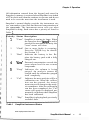
In the text you will find various warnings and notes.
Warning: A warning indicates a n operation which could
cause personal injury if precautions are not
followed.
1
I
I
1
Note: A note indicates an operation which could cause
instrument damage if precautions are not followed.
A note also indicates significant information and is
provided with various procedures.
3
www.equipcoservices.com
Snapshot User's Manual
1
Chapter 1 Introduction
3.
4.
5.
6.
may explode. Check with local codes for possible
special disposal instructions.
Do not open or mutilate the battery pack. Released
electrolyte is corrosive and may cause damage to the
eyes or skin. It may be toxic if swallowed.
Exercise care in handling battery packs in order not
to short the terminals with conducting materials
such as rings, bracelets and keys. The battery or
conductor may overheat and cause burns.
Do not defeat proper polarity orientation between
the battery pack and battery charger.
Charge the battery pack using the charger provided
with or identified for use with this product only in
accordance with the instructions and limitations
specified in this manual. For battery charger use
only Photovac Part No. 365000 (North America),
365008 (United Kingdom), 365009 (Europe).
Excessive Heat
Do not expose the instrument to intense sunlight for
prolonged periods. This may result in a rise in instrument
temperature and loss of oven control.
Exposure to excessive heat may result in instrument
contamination.
Application Module Care
When removing and replacing the application module,
move the instrument to a clean, dust-free environment. If
you are using more than one application module, store the
modules that are not in use in a clean, dust-free location.
See Section 3.3 for details.
Calibration Gas
Adequate ventilation must be provided when Snapshot is
being calibrated.
If compound threshold limit values (TLVs) are exceeded,
you should use a gas bag for sampling and calibration.
To determine the TLV of the compounds contained in the
calibration gas, refer to the Material Safety Data Sheet
(MSDS) supplied with your calibration gas cylinder. See
Section 2.12 for details of calibration using a gas bag.
www.equipcoservices.com
SnapshotUser's Manual
3
Chapter 1 Introduction
A supply of carrier gas must always be available for
Snapshot. Six carbon dioxide 1C02)or nitrogen (N2)cylinders are supplied with the instrument. Replacement cylinders may be obtained in sets of six. (Photovac Part No.
365005 for C02and 365029 for N2).
SnapShot may be used with a serial printer. The printer
must be an Epsonm FX-80, Epson FX-850, a KodakTM
DiconixTM 150, a Diconix 180 (Photovac Part No. 380129),
or the printer must be 100% compatible with one of theae.
The printer must have an RS232 port available.
1.5
Battery Charging
Before beginning operation of Snapshot, the battery pack
must be charged.
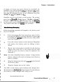
1.
If the instrument has been turned on, turn it off by
pressing the OFF key and stop the flow of carrier gas
by turning the camer gas shut-off valve fully clockwise. See Figure 1.
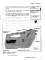
2.
Press the release button on the bottom of SnapShot
and remove the battery pack by sliding it backwards.
3.
Ensure the correct plug is installed on the battery
charger line cord. If i t is not correct for the wall
outlet in your area then it must be replaced. See
Appendix 3.
Note: Use only a SnapShot battery charger. Using another
battery charger will result in damage to the battery
pack or charger.
4.
Plug the charger into the jack located on the front of
the battery pack.
5.
Plug the charger into a n AC outlet.
The LED, on the battery pack, indicates the charge state.
Red indicates the batteryis being charged. Green indicates
the battery is fully charged and ready for use.
www.equipcoservices.com
SnapshotUser'sManual
5
Chapter 1 Introduction
to select the application you need. Use the Arrow
keys to select the desired application and then press
ENTER.
3.
4.
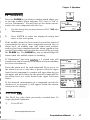
The software version number and the application
number will be now be displayed.
If this is a new applicaton module or a new application from the same module, Snapshot will display
the message Wew application! OK to reset all".
Press Enter to send the new application information
from the module to Snapshot.
Note: When a new application is selected, the datalogger
and all setup information will be cleared.
5.
I1
I
Appli.cation
E l
New O~K ptpol frceas teito an l l
Open the carrier gas shut-off valve. Turn the valve
www.equipcoservices.com
SnapshotUser's Manual
7
Chapter 1 Introduction
9.
After the lamp has been tuned, SnapShot will purge
the column and heat the isothermal column oven.
The instrument status will be "Chck" while the oven
heats. The status will then change to T u r f while
the column is purged for the duration of one analysis.
When the instrument status changes to Tedy" Snapshot
is ready for operation. A new cylinder will provide approximately 8 hours of operation. If the instrument is not in use
you can stop the flow of carrier gas by turning the carrier
gas shut-off valve clockwise. Snapshot will automatically
turn the lamp off when the carrier gas supply is shut off.
The carrier gas shut-off valve does not control the actual
flow rate. The flow rates are set automatically by the
application module. Flow rates will differ from one application module to another.
Note: Do not remove the carrier gas cylinder from Snapshot
until the cylinder is empty. You will know the
cylinder is empty when a "Chck" status is displayed.
Press the TUTOR key. The message will be "Carrier
pressure is now low".
www.equipcoservices.com
Snapshot User's Manual
9
Chapter 2 Operation
All information entered from the keypad and stored in
Snapshot's memory is retained when SnapShot is switched
off. The clock and calendar continue to operate and do not
need to be reset the next time the instrument is used.
Snapshot's normal display provides the instrument status, run number, time, date and detected concentrations of
the compounds. The instrument status tells you what
SnapShot is doing. Each status has a priority as listed in
Table I.
Priority Status Description
1
"Tune" SnapShot is tuning its lamp. When
the lamp has been t u n e d on and is
tuned to the maximum intensity the
"rune" status will clear.
2
"Chck* One or more faults is occurring.
Press the TUTOR key for details.
See Section 5.2.
3
"Batt" Indicates the battery is low. Replace the battery pack with a fully
charged one.
4
"Alrm" Detected concentration exceeds the
preset alarm level for one or more
compounds.
5
"Purg" Indicates t h e column is being
purged. An analysis cannot be
started until the column has purged
itself completely.
6
"Cal"
Indicates the next analysis will be a
calibration run. When the calibration run has started, the instrument status will change to the analysis countdown. After the calibration
run has been completed, the "Cal"
status will again be displayed momentarily to indicate that SnapShot
has been calibrated.
n
7
"Play
SnapShot is playing back previously
recorded data.
Table 1
SnapShot Instrument Status
www.equipcoservices.com
SnapShotUser's Manual
11
Chapter 2 Operation
GRAPH Prints graph of
recorded data
CLEAR Erases the last
number pressed
PLAY
Replays recorded EXIT
data on display
CAL
Sets up next
analysis as cal
Cancels key with
no more changes
ENTER Confirms display
then continues
UP/DOWN Option or Play
speed select
ARROW
Table 2 Continued
If there are no options to the function, the key acts
immediately. The BATT key is one example. If there are
options, the current option is displayed. You are prompted
to display the other options by pressing the arrow keys.
Pressing ENTER confirms that the displayed value is
correct and moves to the next key option.
'
If the function requires numeric input, the current value is
displayed. You can change the value by pressing the
numeric keys. Pressing ENTER confirms that the displayed value is correct and moves to the next key option.
Some functions have multiple steps for options and/or
numeric inputs. These are arranged so that the most
frequently changed inputs are displayed first. Once the
desired changes have been made you can bypass the rest of
the steps by pressing EXIT.
Each key function is described in more detail in the
following sections. Leave Snapshot on and try each key in
turn.
2.3 BATT Key
Press the BATT key to open a window that displays the
battery voltage. The voltage will be 8.5 volts when the
instrument is fully charged. When the voltage drops below
7 volts, a uBatt" status will be displayed and the battery
pack must be removed and recharged. See Section 4.1.
www.equipcoservices.com
Snapshot User'sManual
13
Chapter 2 Operation
The Event Number is the first option to appear. It can be
any number up to 999. Use the Event Number to identify
a particular sampling location or application module. The
Event Number is printed on the tabular reports.
1.
Use the numeric keypad to enter the Event Number.
2.
Press ENTER to confirm the Event Number and
move to the next option.
3.
Press CLEAR to make any changes to the number
you have entered.
The next option is the Period. This option is used to set up
SnapShot for auto analyzing. The Period is the duration for
which SnapShot will cycle continuously. When the Period
ends SnapShot will turn itself off. Setting the Period to any
value greater than 0 will enable auto analyzing and
SnapShot will start a n analysis immediately.
CBARO
If the Period is set to 0, auto analyzing has been turned off.
If auto analyzing has been turned off, the Cycle Time
option will be bypassed.
The next option is the Cycle Time. This is the duration of
each analysis including purging time (if any). If the Cycle
Time that you enter is shorter than the analysis time that
has been preset by the application module, a window will
open and tell you the minimum cycle time. If you change
the Cycle Time during an analysis, the new Cycle Time will
not take effect until the next analysis.
The datalogger can be turned on and off using the Datalogger
option. If the datalogger is turned off, no data will be
logged a n d . analysis information will be lost. If the
datalogger is turned on, SnapShot will record a maximum
of 500 runs. After this, data will be overwritten one
analysis a t a time.
The Date and Time options are next on the SETUP key.
The date and time entered here are used on the normal
display and on the tabular and graphical printouts.
1.
CBARO
15
Ppa
,
I
Use the keypad to enter the correct date. Press
ENTER to confirm the date and press ENTER to
www.equipcoservices.com
SnapShotUsef s Manual
15
-
2.9
Chapter 2 Operation
191
ALARM Key
1 ALARM 1
Press the ALARM key to obtain a window which allows you
to turn the audible alarm indicator "Onn, turn it "Off or
set i t to "Momentary". You will also set the alarm concentration for each compound with this key.
CBARO
1.
Use the Arrow keys to move between "On", "Off and
"Momentary".
2.
Press ENTER to select the displayed setting and
move to the next option.
16.9
ppm
3.4
ppm
34*
pp.
If the audible alarm has been turned on and the detected
concentration for one or more compounds exceeds the set
alarm level, a n audible tone will sound until another
analysis has been completed and the alarm condition has
passed. The audible tone can also be turned off by pressing
the ALARM key. The ALARM key acts to acknowledge the
alarm when the audible alarm is sounding.
If "Momentaryn has been selected, a 5 second tone will
sound a t the end of a n analysis in which a n alarm condition
has been encountered.
Benzene?
Enter the alarm level for each compound. If you try to set
the alarm level to a value that is greater than the upper
limit for that compound, a window will open showing you
the upper and lower limits for the specified compound. Set
the alarm level to a value between the upper and lower
limits.
If the detected concentration of a compound exceeds the
alarm level, a n asterisk (*) will appear beside the concentration on the display.
To1 uene
CBARO
2.10 PLAY Key
The PLAY key plays back previously recorded data. To
begin playback operation:
1.
Press PLAY.
www.equipcoservices.com
SnapshotUser'sManual
17
Chapter 2 Operation
7
2.12 CAL Key
SnapShot will calibrate itself with compounds of known
concentrations contained in a calibration gas mixture. In
order to calibrate Snapshot, all compounds specific to the
application must be contained in the calibration gas.
Note: Only compounds from the application module must
be contained in the calibration gas; no extra compounds and no substituted compounds are allowed.
When you are selecting the calibration gas mixture, keep
in mind the upper and lower concentration limits of the
application module. Use the SETUP key to determine
these values. Snapshot will not allow you to enter a
calibration concentration above the upper limit or below
the lower limit. If you try to enter such a value, a warning
message will be displayed.
On some application modules, compounds have been
grouped together for ease of operation. During calibration
all the compounds that are contained in the group are
identified and a calibration concentration must be entered
for each one. It is only during calibration that you will see
the individual components of the group. When ordering
calibration gas, you must request all application compounds, including the individual components of the group.
Try to obtain each compound a t a concentration that is
close to the value you are expecting to see. For example, if
you are using ,Snapshot for 10 parts per million (ppm)
benzene, try to obtain calibration gas that contains 10 ppm
benzene.
If the calibration gas is toxic and cannot be vented into the
air, a gas bag containing calibration gas may be connected
directly to Snapshot's inlet. You should also use a gas bag
if the concentration of the calibration compounds is greater
than the TLV. See Section 1.2
1.
Connect the regulator to the calibration gas cylinder. See Section 1.4 for specifications on the type of
regulator that is required.
www.equipcoservices.com
SnapshotUser'sManual
19
Chapter 2 Operation
5.
Ensure that the third branch of the calibration
adapter tee is left unobstructed to vent the excess
flow.
If you are using a gas bag for calibration:
1.
Connect the regulator to the calibration gas cylinder. See Section 1.4 for specifications on the type of
regulator that is required.
2.
Use the gas bag adapter to connect the gas bag to the
regulator outlet.
3.
Open the valve on the gas bag and then open the
valve on the calibration gas cylinder.
4.
Fill the gas bag about half full and then close the
calibration gas cylinder.
5.
Disconnect the gas bag from the adapter and empty
it in a well ventilated area. Preferably the gas bag
should be emptied outdoors or in a fumehood.
6.
Flush the bag a few more times with the calibration
gas and then fill it. Close the valve on the gas bag.
To calibrate SnapShot:
1.
If Snapshot is auto analyzing, press the SETUP key
and disable the auto analyzing option by entering 0
as the Period. If the instrument is in the middle of
a run it will stop auto analyzing after i t has finished
the current analysis.
Note: The calibration gas must contain all the compounds
from the application module in order for Snapshot
to calibrate itself correctly. If you are using a n
application module with a compound group, all
coplpounds contained in the group must also be
contained in the calibration gas.
During calibration all the compounds that are contained in the group are identified and a calibration
concentration must be entered for each one. It is
only during calibration that you will see the indiwww.equipcoservices.com
SnapshotUser's Manual
21
Chapter 2 Operation
SnapShot must be calibrated a t least once a day. It must
also be calibrated if the W lamp window is cleaned or if
the W lamp or sample inlet filter is replaced. You should
calibrate SnapShot immediately before the analysis of
critical samples.
If you are using a gas bag to calibrate the instrument, the
gas bag must be refilled with fresh calibration gas each
time a calibration is performed.
If another application module is installed a t any time,
SnapShot mast be calibrated with calibration gas specific
to the new application module.
If another application within the same module is selected,
SnapShot must be calibrated again.
There are currently several different application modules
available for SnapShot. When you calibrate SnapShot all
compounds from the application module must be contained
in the calibration gas.
To obtain calibration gas specific to your application module, contact EQUIPCO a t (888)234-5678.
.
2.13 TABLE Key
SnapShot will print a table of the data from one or more
runs.
1.
1 TABLE 1
Turn SnapShot off.
I
Note: You must turn the instrument off before connecting
or disconnecting the printer cable.
2.
Connect an Epson FX-80, FX-850, Kodak Diconix
150, Diconix 180 or a printer that is 100% compatible with one of these printers to SnapShot with the
RS232 printer cable (Photovac Part No. 365011).
3.
Turn SnapShot on again and press the SETUP key.
Ensure the correct baud rate has been set.
www.equipcoservices.com
SnapShotUser's Manual
23
Chapter 2 Operation
6.
Press the TABLE key. Enter the start and stop run
numbers. Snapshot will now tell you how many
pages will be printed.
2 Pages
CBARO
7.
15
pvn
Press ENTER to send the information to the printer.
While the instrument is printing, the message "Please
wait printing now" will be displayed. While printing is in
progress Snapshot is still analyzing and recording data if
the datalogger is turned on.
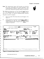
The printout should look like the table in Figure 5 and the
following information will be printed.
a.
The date of the analysis. The start date will be
printed first and then it will only be printed if i t
changes.
b.
The time of each analysis.
c.
The first Event number will be printed and then this
number will only be printed if it changes.
d..
The run number for each analysis.
e.
The highest priority status for each run.
f.
The concentration for each compound.
g.
Compounds that have exceeded their alarm level
will be indicated with a n asterisk (*I.
The data will be printed one line of the table per run.
2.14 GRAPH Key
Use the GRAPH key to print a graph of recorded data for
each compound. One compound will be printed per page.
1.
Turn Snapshot off.
www.equipcoservices.com
SnapShot User'sManual
25
Chapter 2 Operation
I
1
2.
Connect a n Epson FX-80, FX-850, Kodak Diconix
150, Diconix 180 or a printer that is 100% compatible with one of these printers to SnapShot with the
RS232 printer cable (Photovac Part No. 365011).
3.
Turn SnapShot on again and press the SETUP key.
Ensure the correct baud rate has been set.
4.
' Use the PLAY key to determine the s t a h and stop
I
run numbers for the graph.
5.
Ensure there is paper in the printer and that it has
been aligned properly.
6.
Press the GRAPH key. Enter the start and stop run
numbers. SnapShot will now tell you how msny
pages will be printed.
3 Pages
15
CBARO
7.
Press ENTER to send the information to the printer.
SnapShot will begin printing the desired graph output.
While the instrument is printing, the message 'Tlease wait
e printing is in
printing now" will be displayed.
progress Snapshot is still
recording data if
the datalogger is turned on.
pp.
16 ppn
71
Please ualt
p r i n t i n g now
CBARO
ppm
15
PP.
16
pvn
The printout should look like the graph in Figure 6. The
following information will be printed:
(
a.
The compound name.
1
b.
The starting time, ending time and the date for
graphed information.
c.
A compound concentration versus time bar graph.
1
2.15 STARTISTOP Key
I
1
1
The carrier gas must be turned on before the lamp will
begin tuning. SnapShot will beep once when the carrier gas
has been turned on and then beep again when the lamp has
tuned itself.
1
If the instrument has just been turned on, allow 5 minutes
for the oven to heat up and for the column to purge itself
www.equipcoservices.com
SnapShotUser's Manual
27
Chapter 2 Operation
2.
1
Move to the Period option. Type in the length of the
period. See Section 2.7. Press ENTER.
I
1
I
Note:When you enter the period, SnapShot will begin
analyzing immediately. Ensure the instrument is
calibrated and ready to analyze before entering a
Period.
3.
4.
Now enter the Cycle Time. This is the duration of
each run and includes the analysis time and the
purging time, if any. Ifyou try to enter a Cycle Time
that is shorter than the analysis time, SnapShot
will display the minimum Cycle Time.
d
Mlnimum Cycle
15
PPm
Press EXIT to leave the Setup option.
When the analysis is complete, if there is time remaining
in the cycle, SnapShot will purge the column.
Pressing STARTISTOP does not disable auto analyzing. If
you press START/STOP after an analysis has started, you
will abort the current analysis. The column will be purged
for the duration of the Cycle Time and then another
analysis will begin.
SnapShot will continue to auto analyze and record data (if
the datalogger is turned on) until the end of the period. At
the end of the period SnapShot will turn itself off.
If the battery pack requires replacement during the period
you will have to adjust the period duration after the
battery pack has been replaced.
For example, if you set a 5 hour period, the battery pack
will require replacement after 4 hours. When the instrument is re-started with the new battery pack, set the
Period duration to 1 hour to complete the 5 hour period.
To disable auto analyzing:
1.
Press the SETUP key.
2.
Move to the Period option and enter 0 as the period.
www.equipcoservices.com
SnapShotUser's Manual
29
I
Chapter 3
Accessories
SnapShot will print to an Epson FX-80,a n Epson FX-850,
a Kodak Diconix 150, a Diconix 180 or a printer that is
100% compatible with one of these. The printer must have
a n RS232 serial interface.
1.
TurnSnapShot off.
I
Note: You must turn the instrument off before connecting
or disconnecting the printer cable.
2.
Connect the RS232 printer cable (Photovac
Part No. 365011)to the RS232 port on the
back of the SnapShot and then to the
serial port on the printer.
3.
Turn SnapShot on.
4.
Determine the baud rate for your printer.
Refer to the printer user's manual for details.
5.
Press the SETUP key and select the Baud Rate
option. Use the Arrow keys to select the baud rate
corresponding to the printer. The baud rate in the
SETUP option must match the baud rate of the
printer.
Figure 7 SnapShot Rear Ports
If this arrangement does not produce the desired results,
see Sections 5.4 and 5.5.
3.2- Computer
SnapShot will send information stored in its datalogger to
a computer. This option may be used if you need to prepare
reports based on Snapshot's recorded data. This feature
www.equipcoservices.com
SnapShot User'sManual
31
Chapter 3 Accessories
Note: The instructions below will provide you with the
most basic information for using Snapshot with
communications software. Please refer to the software user's manual for specific details of operation.
The following instructions are for Crosstalk XVI Version
3.71. The commands may vary with the version of Crosstalk you are using. To initiate communications between
Snapshot and the computer:
1.
Start Crosstalk. The Status Screen will appear. See
Figure 8.
2.
At the bottom of the Status Screen there.wil1 be a
highlighted bar with the word Command?. If the
word Command? does not appear press < E s o on the
computer keyboard.
-,
CROSSTALK - XVI Status Screen
NAme
Crosstalk default settings
Number
I Speed 9600
DAta
Port
On
9
1
Loaded
STD.
CApt u r e A: \SNAP. OTA
Command ETX ( ^ C )
BReak
End
l ine
-,
,- Filters e t t i n g s
OEbug
Off
LFauto O f f
TAbex
Off
BLankex Off
I N f i 1t e r On
O U t f i 1t e r
Communication parameters
P A r i t y None OUplex
Full
STop
1
EMulate None
Mode
Answer
Key s e t t i n g s
ATten Esc
SWi t c h Home
Off
7
I
-5End
CWait
LWai t
control settings
1
None
None
Avai lab1 e command f i l e s
I
I
C
Figure 8 Crosstalk Status Screen
www.equipcoservices.com
SnapShot User'sManual
33
Chapter 3 Accessories
9.
Turn SnapShot on and press the SETUP key on
SnapShot and ensure the baud rate is set to 9600.
The value you set here must be the same as the baud
rate set in Crosstalk.
10.
Type P O and press <Enter>. Type in 1 if you connected SnapShot to Coml or type in 2 if you connected SnapShot to Com2 and press <Enter>. If you
connected SnapShot to another serial port enter the
corresponding number.
11.
Type MO and press <Enter>.Type i n A to change the
mode to answer.
12.
In order to capture the data and store them on a disk
you must turn the Crosstalk capture command on
and specify a disk to which the data can be stored.
Type CA and press <Enter>. Now type in the disk
drive and the name of the file where you want the
data stored. For example if you want to store the
data in a file called Snap on a floppy disk in drive A,
then type A-\Snap.dta and press <Enter>.
13.
If the word Command? does not appear a t the
bottom ofthe Crosstalk Capture Screen, press <Esc>.
14.
You have now set up Crosstalk to communicate with
SnapShot. Type GO L to begin the downloading
session. The Status Screen will disappear and the
Capture Screen will appear.
15.
Press the SnapShot TABLE key and set the start
and stop run numbers. After SnapShot tells you how
many pages wiIl be printed, press ENTER (on
SnapShot). The logged data will begin to appear on
the computer screen.
When all the data have been sent, press <Esc>.Type
CA off and press <Enter>.This will turn the capture
option off and write the captured file to the disk
drive you specified in step #12.
16.
Press <Home> to return to the Status Screen.
17.
Type QU and press <Enter>. This will end your
communications session.
www.equipcoservices.com
SnapShot User'sManual
35
Chapter 3 Accessories
F
n
w.
Baud Rate
0 1 1 0 0300
0 2400 0 4800
[
E
a
t
a
0 s 0 s
B
0 7
I
.
o m 0 @:em:
0 9600 0 19200
b
Y
@a
lmk=q
[r"t~-l
101.5 0 2
Figure 9 Communicationa Dialog Box
4.
Open the Transfers Window and select the Receive
Text File option. A Receive Text File Dialog Box will
open. See Figure 10.
5.
Type in the desired path and filename for the data
that are to be downloaded. Ensure the path is
correct.
Figure 10
Receive Text File Dialog Box
www.equipcoservices.com
Snapshot User's Manual
37
Chapter 3 Accessories
listed, it cannot be run on that application module. To
determine which compounds can be analyzed on the column press the SETUP key. See Section 2.7.
;'
1
1
1
I
When the application module is installed and the instrument is turned on, the column oven will begin to heat up.
The column oven will maintain a constant column temperature and will eliminate retention time drift. The
actual oven temperature will depend on the application
module.
Some modules contain more than one application. If you
are using one of these modules, you will select a n application when you first turn on the instrument.
Note: When a new application is selected, the datalogger
and all setup information will be cleared. Print or
save the contents of the datalogger before loading a
new application.
To switch between applications:
1.
Turn the instrument off by pressing the OFF key.
off.
You do not need to turn the carier gas
-
Note: You must turn the instrument off before connecting
or disconnecting a new module.
2.
Turn the Snapshot on by pressing the ON key. The
instrument will power up and display the message
"Please turn on carrier gas flow". Press ENTER.
3.
You will now be prompted to select the application
you need. Use the Arrow keys to select the desired
application and then press ENTER.
4.
The software version number and the application
number will be now be displayed.
5.
If this is a new applicaton module or a new application from the same module, SnapShot will display
the message "New application! OK to reset all?".
Press ENTER to send the new application information from the application module to SnapShot.
d
www.equipcoservices.com
Snapshot User'sManual
39
Chapter 3 Accessories
I
6.
Ensure the carrier gas is turned on and allow carrier
gas to flush the column for one hour before beginning operation.
Note: If you have installed a n ethylene oxide application
module, you will need to replace the C02carrier gas
cylinder with a n N, cylinder. See Section 4.2.
7.
Turn the instrument on. The message "New applicationl OK to reset all?" will appear on the display.
Press ENTER. SnapShot will overwrite compound
information from the old application module with
the compound information from the newly installed
application module.
8.
Calibrate the instrument with calibration gas containing all the compounds from the application. See
Section 2.12.
OK t o r e s e t a l l ?
If more than one application module is being used with
SnapShot, store the modules that are not in use with plugs
in the ports. When the module is connected to the SnapShot
store the plugs in the supplied bag. They will remain clean
and ready for use.
The application modules will retain their data indefinitely
and do not have to be connected to SnapShot on a regular
basis.
For specific information about your application, contact
EQUIPCO at (888) 234-5678.
Photovac may be able to develop a custom application
module for your application. A custom application module
is identified by the SnapShot serial number printed on the
module label. This module must be used only with the
Snapshot bearing this serial number.
3.4
Shoulder Strap
Snap one end of the shoulder strap to the connector bail on
the back of Snapshot's handle. Snap the other end to one
of the shoulder strap connectors beside the display.
www.equipcoservices.com
SnapShot User's Manual
41
I
Chapter 4
Routine Maintenance
4.1
Battery Charging
When the instrument status displays "Batt", the battery
pack requires charging. A fully charged battery powers
SnapShot for approximately 4 hours. If the instrument is
to be used for more than 4 hours, c a n y a spare battery
pack. When the first one has been discharged, replace it
with the spare.
Upon return from field work, recharge both battery packs
a s outlined in Section 1.5. Two chargers are required to do
this overnight. Use only the Snapshot battery charger.
Note: Do not leave battery packs uncharged for a n extended period of time. This will result in damage to
the battery packs.
The charger automatically charges a t a high charge rate
until the battery pack is fully charged and then maintains
the full charge with a low continuous charge rate indefinitely so there is no danger of over-charging. A red LED on
the battery pack indicates that the battery is charging.
When the LED turns green, the battery is fully charged
and ready for use.
On average the battery pack will provide 4 hours of
continuous operation. Battery life depends upon the application and is shorter if the backlighting is turned on, if the
ambient temperature is much lower than the application
module set point, or if the instrument is turned on and off
repeatedly.
Note: Leaving Snapshot for more than 3 months without
turning it on may result in the loss of recorded data
and setup parameters. If Snapshot is not used for
long periods of time, turn the instrument on for a
few hours every few months to avoid loss of data.
3
www.equipcoservices.com
SnapShotUser's Manual
43
Chapter 4 Routine Maintenance
5.
If the cylinder is almost empty, the sound of venting
gas will hardly be noticeable. If the cylinder is
nearly full, the venting sound will be quite pronounced. If you are unsure or are in a noisy environment, wait one minute before proceeding. If possible, move to a quieter location to replace the carrier
gas cylinder.
6.
Remove the cylinder by continuing to t u r n i t
counterclockwise five or six turns further. If venting gas is heard a t any point, stop turning and wait
for the cylinder to empty completely.
To install a full carrier gas cylinder:
1.
Ensure the instrument is turned on and the carrier
gas shut-off valve is open.
2.
Insert a new cylinder into the base of the instrument and turn it clockwise until resistance is felt.
You will have to turn the cylinder about five or six
turns.
Ensure you are using N2cylinders for the ethylene
oxide application module. You can determine which
type of cylinder is installed by the color of the grip.
The N2 cylinders have a red grip and the COa
cylinders have a black grip.
3.
Using the cylinder wrench, continue to turn until
the resistance declines as the seal is pierced, and
the cylinder "seats". This will take another one to
one and a half turns. Snapshot will beep once when
the cylinder has seated properly and carrier gas is
flowing. Do not use excessive force.
Note: Do not remove the cylinder to see if it has seated
properly. The cylinder will vent itself upon removal
from SnapShot.
4.
Snapshot will now begin to tune the lamp. If a
"Chck" status message is displayed press the TUTOR key to determine the source of the fault. If
there is a "Carrier pressure is now lown fault, the
cylinder has not been installed properly. See Section 5.2.
www.equipcoservices.com
Snapshot Usef s Manual
45
Chapter 4 Routine Maintenance
9.
Turn SnapShot on and allow it to warm up.
10.
Calibrate SnapShot and then continue normal operation. See Section 2.12 for details of calibration.
4.4 Replacing the UV Lamp
When a lamp fault occurs, the W lamp most likely requires replacement. To replace the W lamp:
1.
Turn SnapShot off.
2.
Turn the carrier gas shut-off valve fully clockwise.
3.
Locate the lampholder below the detector inlet fitting. See Figure .1.
4.
Unscrew the lampholder and pull i t out.
5.
The lamp should be in the long white Teflon tube. If
it is not, carefully tip SnapShot forward into your
hand and the lamp will slide out.
6.
Without touching the window, place the o-ring onto
the new lamp (Photovac Part No. 380029) about 0.5
cm ('/an) from the window end of the new lamp. See
Figure 11.
7.
Place the new lamp in the white Teflon tube of the
lampholder. Screw the lampholder into place.
8.
Turn SnapShot on and allow i t to warm up.
9.
Calibrate SnapShot and then continue normal operation. See Section 2.12 for calibration information.
4.5 Replacing the Sample inlet Filter
Replace the sample inlet filter every 3 to 6 months of use.
If the working environment is dusty, the filter may require
replacement more often. To replace the filter:
www.equipcoservices.com
SnapShot User'sManual
47
Chapter 5
Troubleshooting
5.1
General
If you have a sewice-related question about Snapshot,
consult this manual first. If you cannot find the answer in
this documentation, contact EQUIPCO at (888) 234-5678.
When you call you should have your Snapshot in front of
you. You should also have this manual a t hand. Lastly,
please have the following information ready:
1.
A description of what happened and what you were
doing when the problem occu'rred.
2.
Any corrective action that has been taken.
3.
The exact wording of any messages that appeared
on the screen.
5.2
Snapshot Fault Messages
When a,"ChckSstatus is displayed Snapshot's operation is
compromised by a fault condition. Press the TUTOR key to
obtain a description of the fault.
The faults below are listed by priority. If more than one
fault is occurring a t a time, the fault with the highest
priority will be displayed first. Press the TUTOR key
again and if there is another fault its description will be
displayed.
Use the basic corrective action listed here to correct minor
faults.
Fault:
Ambient drifted1 Calibrate now
Cause:
The ambient temperature has changed by
www.equipcoservices.com
SnapShot User'sManual
49
Chapter 5 Troublesh~oting
appears then replace the W lamp. See
Section 4.4.
Fault:
Calibration error occurred
error occurred
Cause:
Calibration gas is not being supplied correctly.
Action:
Ensure the calibration gas cylinder valve
is open all the way.
Action:
Ensure there is calibration gas in the cylinder. Open the cylinder and check the
contents gauge.
Action:
If pressurized calibration gas is beingused,
ensure the delivery pressure is maintained
a t 5 psig (35 kPa). Ensure the delivery
pressure does not exceed 5 psig (35 kPa).
If you are using the Photovac calibration
gas regulator, i t has been preset to deliver
250 mumin. Use a flowmeter to check the
flow rate.
Action:
If a gas sampling bag is being used, ensure
the valve on the bag is open before connecting it to Snapshot.
Action:
Before beginning a calibration with the
STARTfSTOPkey, turn on the calibration
gas and allow the adapter tee and adapter
tubing to be flushed with calibration gas.
Action:
There is a n undetermined problem. Contact the EQUIPCO Service Department a t
(888)234-5678.
Cause:
Calibration gas does not contain all of the
compounds for the application.
Action:
In order for Snapshot to calibrate itself
correctly, all the compounds from the application module must be contained in the
calibration gas.
15
ppa
www.equipcoservices.com
Snapshot User's Manual
51
1
1
Chapter 5 Troubleshooting
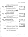
Fault:
Carrier pressure is n o w low
1
Cause:
Carrier gas cylinder is empty.
1
1
Action:
Replace the carrier gas cylinder. See Section 4.2.
Cauee:
The carrier gas shut-offvalve has not been
opened.
Action:
Ensure the carrier gas shut-off valve is
turned fully counterclockwise. The carrier shut-off valve is located on the side of
the instrument. See Figure 1.
Cause:
The cylinder has not been installed properly.
Action:
Rotate t h e cylinder one quarter t u r n
counterclockwise. If you hear the sound of
venting gas, then the seal on the cylinder
has been broken. Use the cylinder wrench
to tighten the cylinder until you hear
Snapshot beep. Then turn the cylinder a
further one to one and a half turns. This
should start the flow of carrier gas.
1
1
1
I
1
1
1
I
1
1
I
I
1
1
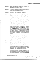
Cause:
The cylinder is defective.
I
Action:
Carefully remove the cylinder and properly dispose of it. Inspect the new cylinder
before installing it into Snapshot. The
seal on the cylinder must be intact. D o
n o t touch the seal. See Section 4.2 for
installation instructions.
1
1
If you do not hear venting gas when you
loosen the cylinder, the seal has not been
broken. Use the cylinder wrench to tighten
the cylinder until you hear Snapshot beep.
If you cannot tighten the cylinder any
further and the seal has not been broken,
the cylinder may be defective. See the
instructions below.
www.equipcoservices.com
Snapshot User'sManual
53
Chapter 5 Troubleshooting
Action: Turn SnapShot off and install the desired
application module. SnapShot cannot be
operated without an application module.
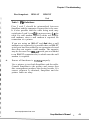
Fault:
Module change detected
Cause:
The application module has been changed
before SnapShot was turned off.
Action: Turn SnapShot off, then on again. The
new application module will be intialized. In the future, do not remove a n
application module until after you have
turned the instrument off.
Fault:
Detector signal is saturated
Cause:
The detector signal has gone offscale for
more than 15 seconds indicating possible
column contamination.
Action:
Allow the column to purge itself for a few
minutes. Then begin another analysis.
Fault:
Checksum did not verify
Cause:
Internal software problem.
Action: Contact the EQUIPCO Service Department
a t (888)234-5678.
Fault:
Please check module.
Cause:
SnapShot cannot send calibration information to the application module. There
may be a loose connection between
SnapShot and the application module.
Action: Turn SnapShot off and remove the application module and then reconnect it. Ensure the 15-pin connector is securely attached. Turn SnapShot on again.
www.equipcoservices.com
SnapShotUser'sManual
55
Chapter 5 Troubleshooting
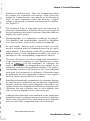
Action:
Calibrate the instrument as outlined in
Section 2.12. After the instrument has
been calibrated start a run using the calibration gas as a sample. All the compounds should be displayed. If they are
not contact the EQUIPCO Service Department at (888)234-5678.
Cause:
Wrong type of carrier gas being used.
Sensitivity may be reduced.
Action:
If you are using an application module for
ethylene oxide, you must use nitrogen as
the carrier gas. Ensure an Nzcylinder is
installed. The Nzcylinders have a red grip
and the C02 cylinders have a black grip.
Cause:
Lamp window is dirty. Sensitivity may be
reduced.
Action:
Clean the lamp window. See Section 4.3.
Cause:
There is an undetermined problem.
Action:
Contact the EQUIPCO Service Department
at (888)234-5678.
Problem: Preseing STARTBTOP key has no effect.
Cause:
There is a fault condition other than a
"Calibration Error" or a n "Ambient has
Drifted" fault. If a n analysis cannot be
started due to a fault condition then the
message "Fault condition prevents start"
will be displayed.
Action:
Press the TUTOR key to determine the
source of the fault. Correct the fault. See
Section 5.2. When the fault message has
cleared and the status has returned to
rtedy", press the STARTISTOP key.
If a "Calibration Error" or "Ambient has
Drifted" fault has occurred, Snapshot will
www.equipcoservices.com
SnapshotUser's Manual
57
Chapter 5 Troubleshooting
Action:
Make sure that the printer is "on line", a s
shown on its control panel.
Action:
Check the ribbon, the print wheel or cartridge, and the paper supply.
Cause:
Printer is not configured properly.
Action:
Many printers have a set of configuration
(DIP) switches. Generally, Snapshot expects these switches to be set in the factory default settings.
Many printers have switches for enabling
automatic line feeds when receiving a carriage return. These switches should be set
to carriage returns only, which is normally the factory default setting.
Some printers have switches or control
panels that enable you to set the printer
for different modes, such as sans serif,
letter quality, or compressed text. Do not
use these controls with SnapShot. If you
do use them, you may cause your tabular
or graphed output to be printed incorrectly.
You need to set the correct baud rate and
parity. If the baud rate or parity is incorrect, the printer may not print or the
output may be garbled.
Cause:
Printer is not compatible.
Action:
When a device such as Snapshot is used to
download information to a printer, the
information is sent a s a series of codes.
These codes must be formatted in such a
way that the printer can interpret them
and print the information properly.
There are several industry standards for
the formatting of printer codes, also known
as printer protocols. Epson FX-80, IBMCQ
www.equipcoservices.com
SnapShot User'sManual
59
Chapter 5 Troubleshooting
Action:
5.5
If the baud rate is correct it is possible
that the transfer rate is too high and
information is being lost. Lower the baud
rate of the computer (through the communication software) or the printer (DIP
switch settings) and set Snapshot accordingly.
Serial Communication
If, after having followed the procedure i n Section 3.2,
communications cannot be established with a computer,
the problem may lie with the hardware connections or the
printer cable configuration.
1.
If you are not using a Snapshot printer cable,
ensure the RS232 cable you are using is configured
correctly. See Figure 12.
25 Pln Male
Connector
Figure 12
2.
9 Pin Female
Connector
Prlnter Cable Pinouts
Ensure Snapshot is connected to the serial port of
the computer.
www.equipcoservices.com
SnapshotUser's Manual
61
Chapter 5 Troubleshooting
Pin Snapshot
IBM-AT
IBM-XT
Rxd
Table 3
Pin Definitions
Pins 2 and 3 should be mismatched between
SnapShot and the computer. Ensure this is the case.
It is also possible that the cable being used, may
switch pins 2 and 3 even ifit is not necessary, i.e. the
cable is a null modem. IBM-AT cables are usually
null modems, since a null modem is required for
connection to a printer.
If you are using an IBM-AT and find that a null
modem is not required, it is possible that a n IBM-XT
serial port has been added to an expansion slot and
thus does not require a null modem. The opposite
may be the case if a n JBM-AT serial port was added
to an IBM-XT expansion slot, in which case the null
modem is required.
4.
Ensure all hardware is working properly.
Use a printer to test both SnapShot and the cable.
Connect SnapShot to the printer and ensure that
this arrangement produces the desired results. If a
correct printout is obtained, SnapShot and the
printer cable are okay.
www.equipcoservices.com
SnapShotUser's Manual
63
Chapter 6 Technical Description
desorbed a t different rates. Thus, the components within
the sample are separated and emerge (elute) from the
column in a characteristic time known as the Retention
Time. As each component enters the detector, a signal
voltage is generated, processed and shown on the display.
See Figure 15.
The Retention Time of each peak gives an indication of
what the contaminant is, while the size (area or height) of
the peak indicates how much is present. SnapShot does not
display the actual peaks.
Chromatography is a comparative technique of analysis.
The identities and concentrations reported by SnapShot
are based on those of previously analyzed standards.
In each sample analysis, peak retention times are compared to retention times of compounds stored in the application module. If they match (within the peak recognition
window stored in the application module), the peak is
identified a s the corresponding compound of interest.
The ratio of peak area to known compound concentration
is the sensitivity (response to concentration ratio, measured in mVSfppm) for the compound. To calculate the
peak's concentration, its integrated area is divided by the
sensitivity stored in the application module. The application module calculates the sensitivity for each compound
each time the instrument is calibrated. Calibration must
be performed for each compound of interest on a regular
basis to ensure the sensitivity is accurate.
SnapShot automatically compensates for response changes
by analyzing the calibration gas periodically. Application
module retention times and compound sensitivities are
updated whenever SnapShot is calibrated. SnapShot also
calculates the new retention time to old retention time
ratio for each compound in the calibration gas.
Although the isothermal oven contained in the application
module increases retention time and sensitivity stability,
these values may drift. If the instrument is not calibrated
a t least once daily, compounds may not be detected.
www.equipcoservices.com
SnapShot User'sManual
65
Chapter 6 Technical Description
length carries 10.6 electron volts (eV) of energy. The UV
light is emitted from the lamp and is directed a t the carrier
gas eluting from the column. When light of this energy hits
the eluting molecules, they may become ionized. See Figure 16.
The lamp generates photons which ionize' specific molecules in the gas stream. Many of the chemicals considered
pollutants, including most hydrocarbons, are ionized. The
permanent air gases (argon, carbon dioxide, nitrogen,
oxygen, water vapor, etc.) require a relatively high energy
for ionization, and are not ionized by the UV photons.
Whether or not a certain molecule is ionized depends upon
its Ionization Potential (IP). If the IP of a molecule is less
than 10.6 eV it will most likely be ionized eficiently. If the
I P is greater than 10.6 eV, it is not likely to be ionized well.
Most of the permanent air gases including water vapor
have IPS over 12 eV. This means that the carrier gas and
the sample matrix are not ionized.
After the compounds have been ionized by the lamp, the
ionized particles in the detector cell are subjected to a
continuous electric field between the repeller electrode
and the collector electrode. The ions move in the electric
field, generating a current which is proportional to the
concentration of the ionized molecules in the detector cell.
An electrometer circuit converts the current to a voltage
which is then fed to the microprocessor.
www.equipcoservices.com
SnapshotUser's Manual
67
Appendices
2.
Warranty
Snapshot is warranted for one year against defects in
materials and workmanship.
Photovac Incorporated warrants that its manufactured
products (except Detector W Lamps which carry specific
warranties) will be free from defects in materials and
workmanship for a period of one (1) year from the date of
receipt by the Customer. This Warranty applies to proper
use of the equipment by the customer and may be voided if,
in the opinion of Photovac Incorporated, the product has
been abused or treated in a negligent manner so a s to cause
damage or failure. Negligent use includes, but is not
limited to, exposure of the internal parts of the equipment
to water. Damage caused thereby is expressly excluded
from this Warranty.
Photovac and its vendors disclaim any implied warranties
of merchantability or fitness for a particular purpose.
Photovac and its vendors will not be liable for any indirect,
special, incidental, or consequential damages irrespective
of whether Photovac or the vendor has advance notice of
the possibility of such damages.
When Photovac is made aware of a problem in Snapshot
which would be eligible for remedy under Warranty, it will
issue a Return Authorization Number to the Customer. No
return will be accepted unless such authorization has been
obtained.
If, upon receipt of the equipment, Photovac determines
that repair or replacement should be done under Warranty, Photovac's sole liability shall be for labor and
materials necessary to put the equipment into proper
order and return it to the Customer as promptly as possible. In lieu of repair or replacement, Photovac may a t its
sole discretion, issue credit for any product.or part returned which Photovac's examination shall disclose to its
satisfaction to have been defective. Photovac is in no way
responsible for any inconvenience or loss, consequential or
incidental, caused to the Customer as a result of the
equipment being out of commission.
www.equipcoservices.com
Snapshot User'sManual
69
IIndex
AC Plug
Battery Charger 70
Accessories
Application Modules 38
Included 4
Optional 4
Printer Cable 31
Shoulder Strap 41
Three Meter Probe 42
Adapter Tee
Calibration 4, 20
Adapter Tubing
Calibration 4, 20
Alarm
Indicator 17
ALARM Key 17
Alrm Status 11
Ambient Drifted!
Fault 49
Analysis
Automatic 15, 28
Calibration 22
Starting 28
Stopping 28
Analyzing Samples 28
Application Module 8
Care 3
Changing 40
Compound Information 16
Custom 41
Data Not Stored 56
Default Values 56
Description 38
Ethylene Oxide 6, 45
Fault 55
Flushing 41
Hex Key 40
Number 10
Storage 41
Switching Applications 39
Applications Department
Technical Services 41
Audible Alarm Indicator 17
Audio Output
Specifications 68
Auto Analyzing
Cycle 15
Disabling 28, 29
Enabling 28
Interruption ,29
Period 15
Auto Off 29
BATl! Key 13
Batt Status 11
Battery Charger
AC Plug 70
Jack 5
LED 43
Snapshot 5
Specifications 68
Battery Pack 8
Care and Maintenance 2
Charging 5, 6, 43
Damage To 14
LED 5
Life 6, 29, 43
Maintenance 2, 43
Removal 5
Specifications 68
Voltage 13
Baud Rate 16, 34
Setting 60
www.equipcoservices.com
Snapshot Uset's Manual
71
Index
Grip 45
Replacement 5
Replacing 44
Cylinder, Cam'er Gas
Carbon Dioxide 41, 45
Grip 45
Installation 6, 8
Nitrogen 45
Wrench 45
Data Bits 34
Datalogger 15
Changing Application 7, 39, 40
Erased Data 56
Memory 68
Using 10
Date, Setting 58
Detection Limits
Application Module 56
Detector
Photoionization 66
Replacing W Lamp 47
Signal is Saturated
Fault 55
Specifications 68
Voltage 50
DIP Switches 59
Direct Sunlight
Exposure to 3, 50, 54
Disabling
Auto Analyzing 29
Display 8
Specifications 68
EDIT Key 18
Entry Emor 56
Ethylene Oxide
Application Module 6, 45
Packed Column 38
Event Number 15
Excessive Heat
Snapshot Exposure to 3
EXIT Key 14
Exposure to Sunlight 50, 54
Fault
Ambient Drifted 49
Calibration Error 5 1
Carrier Pressure is Now
Low 53
Detector Signal is Saturated 55
Identification 12
Lamp Could Not Be
Started 50
Messages 49
Module Change Detected 55
Module Not Installed 54
Oven Temperature is
Above Setting 54
Oven Temperature is
Below Setting 54
Status 44
Flow Rate 9, 40
Gas Bag 3, 21
Gas Chromatography 64
Gender Changer
Cable 62
GRAPH Key 25
Graphical Output 27
Grip, Carrier Gas Cylinder 45
Group
Compounds 19
Hex Key 40
www.equipcoservices.com
SnapshotUser'sManual
73
Index
Module Not Installed
Fault 54
Nitrogen Carrier
Gas 6, 45, 57
Normal Display 10
Normal Operation
Troubleshooting 56, 58
Null Modem 62
O-ring Seal 46
Operational Troubleshooting 56
Outdoor Operation 50. 54
Oven
Temperature Fault 54
Warm-up Time 27
]
1
I
1
I
I
1
I
I
I
t
Parallel Port
Identification 62
Parity 34
Period 15, 29
Photoionization Detector
Technical Deswiption 66
Pin Definitions
Printer Cable 62
PLAY
Key 17
Status 11
Playback Speed 18
Pneumatics 38
Printer
Cable 62
Cable Pin Definitions 62
Cable Specifications 61
Compatibility 59
Configuration 59
DIP Switch Setting 59
Exit hinting 14
Protocols 59
Troubleshooting 58
Using With Snapshot 31
Will not Print 58
Printing 23
Troubleshooting 58
Protocols, Printer 59
Purg Status 9, 11
Redy Status 12
Regulator
Calibration Gas 4
Connection 19, 21
Remote Sampling 42
Repair Facility 70
Replacing
Application Module 40
Camer Gas Cylinder 44
Sample Inlet Filter 47
UV i a m p 47
Retention Time 65
Routine Maintenance 43
M 2 3 2 Serial Interface 60
Run Number 10
Safety Practices 2
Sample
Bag 19
From Remote Location 42
Inlet 8
Inlet Filter 47
Sensitivity 65
Improving 57
Serial
Communications 61
Output, Specifieations 68
Port, Identification 62
Service
Department 49, 70
www.equipcoservices.com
SnapshotUser'sManual
75