1
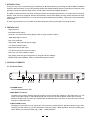
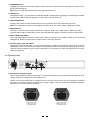
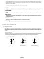
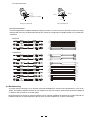
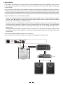
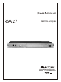
User's Manual
RSA 27
Realtime Analyzer
R
LTO
www.altoproaudio.com
Version 1.3 October 2005
English
˙Fuse
SAFETY RELATED SYMBOLS
CAUTION
RISK OF ELECTRIC SHOCK
DO NOT OPEN
This symbol, wherever used, alerts you to the presence of un-insulated and dangerous voltages within the product enclosure. These are voltages that
may be sufficient to constitute the risk of electric
shock or death.
This symbol, wherever used, alerts you to important operating and maintenance instructions.
Please read.
Before turning the product ON, make sure that it is
connected to Ground. This is to prevent the risk of
electric shock.
Never cut internal or external Ground wires. Likewise,
never remove Ground wiring from the Protective
Ground Terminal.
Always install in accordance with the manufacturer's
instructions.
AC mains (Alternating Current)
Hazardous Live Terminal
ON:
˙Protective Ground
˙Operating Conditions
Protective Ground Terminal
∼
To prevent fire and damage to the product, use only
the recommended fuse type as indicated in this
manual. Do not short-circuit the fuse holder. Before
replacing the fuse, make sure that the product is
OFF and disconnected from the AC outlet.
To avoid the risk of electric shock and damage, do
not subject this product to any liquid/rain or moisture.
Do not use this product when in close proximity to
water.
Denotes the product is turned on.
OFF: Denotes the product is turned off.
WARNING
Describes precautions that should be observed to
prevent the possibility of death or injury to the user.
CAUTION
Do not install this product near any direct heat source.
Do not block areas of ventilation. Failure to do so
could result in fire.
Keep product away from naked flames.
Describes precautions that should be observed to
prevent damage to the product.
Disposing of this product should not be
placed in municipal waste and should be
Separate collection.
IMPORTANT SAFETY INSTRUCTIONS
Read these instructions
Follow all instructions
Keep these instructions. Do not discard.
Heed all warnings.
WARNING
Only use attachments/accessories specified by the
manufacturer.
˙Power Supply
Ensure that the mains source voltage (AC outlet)
matches the voltage rating of the product. Failure
to do so could result in damage to the product and
possibly the user.
Unplug the product before electrical storms occur
and when unused for long periods of time to reduce
the risk of electric shock or fire.
˙External Connection
Always use proper ready-made insulated mains
cabling (power cord). Failure to do so could result
in shock/death or fire. If in doubt, seek advice from
a registered electrician.
˙Do Not Remove Any Covers
Within the product are areas where high voltages
may present. To reduce the risk of electric shock do
not remove any covers unless the AC mains power
cord is removed.
Covers should be removed by qualified service
personnel only.
No user serviceable parts inside.
1
˙Power Cord and Plug
Do not tamper with the power cord or plug. These are
designed for your safety.
Do not remove Ground connections!
If the plug does not fit your AC outlet seek advice from
a qualified electrician.
Protect the power cord and plug from any physical
stress to avoid risk of electric shock.
Do not place heavy objects on the power cord. This
could cause electric shock or fire.
˙Cleaning
When required, either blow off dust from the product
or use a dry cloth.
Do not use any solvents such as Benzol or Alcohol.
For safety, keep product clean and free from dust.
˙Servicing
Refer all servicing to qualified service personnel only.
Do not perform any servicing other than those instructions contained within the User's Manual.
Preface
Dear Customer:
Thanks for choosing ▲LTO RSA 27 Realtime Analyzer and thanks for choosing one of the results of ▲LTO AUDIO
TEAM job and researches.
For our ▲LTO AUDIO TEAM, music and sound are more than a job...are first of all passion and let us say...our obsession!
We have been designing professional audio products for a long time in cooperation with some of the major brands in
the world in the audio field.
The ▲LTO line presents unparalleled analogue and digital products made by Musicians for Musicians in our R&D
Centres in Italy, Netherlands, United Kingdom and Taiwan. The core of our digital audio products is a sophisticated DSP
(Digital sound processor) and a large range of state of the art algorithms which have been developed by our Software
Team for the last 7 years.
Because we are convinced you are the most important member of ▲LTO AUDIO TEAM and the one confirming the quality
of our job, we would like to share with you our work and our dreams, pay attention to your suggestions and your comments.
Following this idea we create our products and we will create the new ones! From our side, we guarantee you and we will
guarantee you also in future the best quality, and the best fruits of our continuous researches and the best prices.
The RSA 27 Realtime analyzer has several features: simple operation interface, realtime spectrum analyzing tool, pink
noise generator and optimizing stage monitor sound quality etc.. You can reduce the feedback effectively depending
on the RSA 27 display. For further details, please go through the user's manual carefully.
Nothing else to add, but that we would like to thank all the people that made the ▲LTO RSA 27 Realtime Analyzer a
reality available to our customers, thank our designers and all ▲LTO staff, there to make possible the realization of
products containing our idea of music and sound and there to support you, our customers, in the best way, conscious
that you are our best richness.
Thank you very much.
▲LTO AUDIO TEAM
2
TABLE OF CONTENT
1. INTRODUCTION ....................................................................................................................................4
2. FEATURE LIST .....................................................................................................................................4
3. CONTROL ELEMENTS..........................................................................................................................4
3.1 The Front Panel
3.2 The Rear Panel
4. INSTALLATION & CONNECTION ........................................................................................................6
4.1 Audio Connection
- Wiring Configuration
- In Line Connection
4.2 Rack Mounting
5. APPLICATION.........................................................................................................................................8
6. TECHNICAL SPECIFICATIONS ...........................................................................................................9
7. BLOCK DIAGRAM .............................................................................................................................10
8. WARRANTY ...........................................................................................................................................11
3
1. INTRODUCTION
Thank you very much for expressing you confidence in ▲LTO products by purchasing our ▲LTO RSA 27 Realtime
Analyzer. With the RSA27 you have acquired the flexible and applied realtime spectrum analyzing tool and pink noise
generator, which can optimize stage monitor sound quality and reduce feedback problems.
The RSA 27 offers the simple and clear operation interface and excellent performance. It contains the four pushingbuttons, each of them is equipped with the LED indicator; 28 bar LEDs display, through which, the RSA can react
readily on program materials, then you can find the specific feedback points easily; a input gain control and a MIC
input socket.
In order to get the best out of your RSA 27 Realtime Analyzer, please go through this manual carefully.
2. FEATURE LIST
˙Signal rack unit
˙Illuminated power switch
˙27 band in 1/3 octave ISO centers display within a range of 40Hz to 16kHz
˙±3dB/±6dB range for switch
˙Pink noise generator
˙Switch-able +48V phantom power supply
˙1/4" TRS microphone input
˙Balanced XLR AUX MIC input
˙1/4" TRS and XLR connectors for output
˙Pink noise 1/4" TRS unbalance output
˙High quality parts and rigid configuration for long life and full credibility
˙Manufactured under QS9000, VDA6.1 certified management system
3. CONTROL ELEMENTS
3.1 The Front Panel
2
4
40
50
63
80
100
125
160
200
250
315
400
500
630
800
1K
1.25K 1.6K
2K
2.5K 3.15K
4K
5K
6.3K
8K
10K 12.5K 16K
+
CLIP
0
16
+15
±3dB
20
RSA27
+8
±6dB
R
40
LTO
0
0
ON
-8
MIC INPUT
10
-12
dB
GAIN
60
+12
PHANTOM
LINE
PINK NOISE
RANGE
3
-
-24
INPUT
LEVEL
INPUT
5
6
7
REALTIME
ANALYZER
OFF
-15
40
50
63
80
100
8
125
160
200
250
315
400
9
500
630
800
1K
1.25K 1.6K
2K
2.5K 3.15K
4K
5K
6.3K
8K
10K 12.5K 16K
POWER
1
1. POWER Switch
Turn the apparatus ON or OFF.
2. MIC INPUT Connector
The MIC input is used to feed the external program source to signal path. Depend on the LINE switch, you can
select to input MIC signal or LINE signal through the connector. For further details, please refer to the (5).
Besides, the MIC input connector is in parallel with the AUX MIC input connector on rear panel, but is used to
input prior to AUX MIC input.
3. INPUT GAIN Control
Rotating this control will give you proper gain. The control is provided with two different indication rings, when
releasing the LINE switch (5), you should read the inside ring (10dB ~ 60dB) indication; otherwise, pressing the
switch allows you read the outside ring (-12dB ~ +12dB) indication.
4
4. PHANTOM Switch
Engaging this button will provide the standard +48V DC power for most condenser microphones, and the corresponding LED will light up.
Note: Plug in the microphone well before turning phantom power on.
5. LINE Switch
Through this switch, you can select to input MIC signal or LINE signal. Engaging is for LINE signal, and the
corresponding LED will light up; otherwise, for MIC signal, and the LED is off.
6. PINK NOISE Switch
Engaging this switch is used to activate the pink noise generator, which will provide the pink noise.
Note: For avoiding the unexpected noise appear, please turn off your system before engaging this switch.
7. RANGE Switch
This button is used to switch range mode between ±3dB and ±6dB. Up for ±3dB; down for ±6dB. It can determine the 3dB or 6dB per LED scales on each band, and affect the display of frequency spectrum LED meters.
8. INPUT LEVEL LEDs Meter
This 7-digit meter tells you the level of input signal, and the range goes from -24dB to +15dB. In case of the Clip
LED lights up, please turn down the input gain control to avoid any distortion.
9. Frequency Spectrum LEDs Meter
Through the 27-band LEDs meter, you can grasp the frequency realtime change easily. There are three sorts of
LED displays, when the response is too high in corresponding frequency band, the red LED lights up; when the
response within the setting range, the green LEDs light up; in the same way, when the response is too low, the
yellow LEDs light up.
3.2 The Rear Panel
10
14
110-120V
USE ONLY WITH A 250V FUSE
EMPLOYER UNIQUEMENT AVEC
UN FUSIBLE DE 250V
220-240V
AC INPUT
95-120V/∼ 210-240V6
∼ 0-50Hz
Rated Power Consumption 21W
+ TIP/PIN 2
- RING/PIN 3
SLEEVE/PIN 1
LEVEL
FUSE:
J.T.
210-240V: T250mAL 250VAC
95-120V: T315mAL 250VAC
REPLACE FUSE WITH
CORRECT TYPE ONLY
Apparaten skall anslutas till
jordat uttag nar den ansluts
till ett natverk
A101
1
11
2
INPUT
OUTPUT
MAIN
3
PINK NOISE
13
15
AUX MIC
12
10.Fuse Holder / Voltage Selector
This is a dual voltage unit. Before you attempt to connect and operate the unit, please make sure that your local
voltage matches the voltage on the fuse holder cover.
Caution: The fuse protecting the AC supplies circuits of this unit. The fuse can only be changed by a qualified
technician, in the event of a fault or changing the supply voltage. If the fuse continues to blow after replacing,
discontinue use of this unit before repaired.
220-240V
110-120V
USE ONLY WITH A 250V FUSE
EMPLOYER UNIQUEMENT AVEC
UN FUSIBLE DE 250V
USE ONLY WITH A 250V FUSE
EMPLOYER UNIQUEMENT AVEC
UN FUSIBLE DE 250V
220-240V
110-120V
THIS IS SET FOR
110V AC TO 120V
AC OPERATION
THIS IS SET FOR
220V AC TO 240V
AC OPERATION
5
The fuse holder above the AC connector on the rear of the chassis has 3 triangular markers (please refer to
the above pictures), with two of these triangles opposing each other, your unit is set to the operating voltage
printed next to these markers.
To change, pull fuse holder out and rotate 1800, then push in again.
11.AC Inlet
This connector is meant for the connection of the supplied main cord. Do not insert power cord into unit until
voltage has been correctly set. Do not plug power cord into AC power until voltage has been correctly set.
12.AUX MIC INPUT
The XLR connector is parallel with MIC INPUT, which is used to input the signal from a low impedance microphone.
13.MAIN OUTPUT
These connectors are used to output the signal. You can output the signal via the balanced XLR connector or
1/4" TRS phone jack.
14.LEVEL Control
This control is used to boost the level for signal from pink noise generator.
15.PINK NOISE
The 1/4" TRS connector is used to output pink noise to external sound system.
4. INSTALLATION & CONNECTION
4.1 Audio Connection
Both XLR and 1/4" TRS connectors are available on your RSA 27. In this way you can interface your RSA 27 in
several different ways without experiencing any noise or signal loss. You can use your RSA 27 with single instrument
using the mixer's main insert or on the complete mix connecting the RSA 27 in between the mixer and the power
amplifier.
- Wiring Configuration
Either the 1/4" TRS phone jack or the XLR connector can be wired in balanced and unbalanced modes, which will
be determined by the actual application status, please wire your system as the following wiring examples:
˙For 1/4" Phone jack
+
Tip
+
-
Tip
Ring
Sleeve
Sleeve
TS Type Unbalanced
TRS Type Balanced
6
+
Ring
Tip
Sleeve
TRS Type Unbalanced
˙For XLR connector
Pin2 (+)
Pin2 (+)
Pin3 (-)
Pin3 (-)
(Linked to Pin1 manually,
)
Pin1 ( )
Pin1 ( )
XLR Type Unbalanced
XLR Type Balanced
- In Line Connection
For these applications the RSA 27 Realtime Analyzer provides 1/4" TRS connectors and XLR connectors to easily
interface with most any professional audio device. Follow the configuration examples below for your particular
connection.
˙Balanced
TIP RING SLEEVE
Tip
Ring
Sleeve
SLEEVE RING TIP
3
3
1
1
2
2
1
3
2
TIP RING SLEEVE
Tip
Ring
Sleeve
1
2
1
2
3
3
Tip
Ring
1
2
3
Sleeve
˙Unbalanced
1
Tip
Ring
3
2
Sleeve
TIP RING SLEEVE
Tip
1
3
2
Sleeve
1
2
3
1
2
3
1
TIP SLEEVE
2
3
1
2
3
Tip
TIP SLEEVE
Sleeve
SLEEVE TIP
Tip
Ring
TIP RING SLEEVE
SLEEVE RING TIP
Cent r e
Screen
Tip
Sleeve
Tip
Ring
Sleeve
Sleeve
Tip
Cent r e
Sleeve
Screen
Tip
Ring
Centre
Sleeve
Screen
TIP SLEEVE
TIP RING SLEEVE
2
2
3
3
1
1
1
2
3
1
2
3
4.2 Rack Mounting
The most secure mounting is on a universal rack shelf available from various rack manufactures or your music
dealer. The RSA 27 Realtime Analyzer fit one standard 19" rack unit of space. Please allow at least an additional
4" depth for the connectors on the rear panel.
Be sure that there is enough air space around the unit for sufficient ventilation and please do not place the RSA 27
Realtime Analyzer on high temperature devices such as power amplifier etc. to avoid overheating
7
5. APPLICATION
In this chapter, we will explain how to use and wire your RSA 27 Realtime Analyzer. In live application, the RSA 27 can
be as a frequency realtime spectrum analyzer or as a pink noise generator. For further details, please read following
content carefully.
First, let's catch on the pink noise, which is defined as random noise that has been weighted with frequency to produce
constant noise power per octave, while one octave is added, the noise power is attenuated by 3dB. Because the ear
of human being reflects the logarithm effect to the sound, so the pink noise is heard as the same level for each octave.
Just because of this character, the pink noise is always used in the sound reinforcement system to adjust the equalizer.
Next, let's introduce how to use the RSA27 in system.
Usually, it is difficult to grasp the change of frequency spectrum in stage monitor. In order to detect the response
problems in time, ▲LTO RSA 27 provides easy and useful operation interface, which contains 27 bands LEDs display
that are used to read the program materials real time.
The RSA 27 is used to visually judge the character of pink noise signal received by the measurement facilities, you
may adjust the EQ to optimize the response of a sound system based on RSA 27 LEDs display. If there are feedback
occurs on some frequency band in system via observing the LEDs display, you can kill it through adjusting the level in
system in time.
Generally speaking, the frequency response of system is very flat, so you will look the LEDs display of RSA 27 like at
the same level. If some frequency band is out of the level, through the RSA 27 display you can adjust the EQ to get
the best result.
In any case, the RSA 27 Realtime Analyzer is very useful tool.
Here, we introduce the connection of RSA 27 in a system simply, perhaps, it will help you a lot.
110-120V
USE ONLY WITH A 250V FUSE
AVEC
EMPLOYER UNIQUEMENT
UN FUSIBLE DE 250V
220-240V
AC INPUT
95-120V∼/210-240V∼60-50Hz
Rated Power Consumption 21W
+ TIP/PIN 2
- RING/PIN 3
SLEEVE/PIN 1
LEVEL
FUSE:
J.T.
210-240V: T250mAL 250VAC
95-120V: T315mAL 250VAC
REPLACE FUSE WITH
CORRECT TYPE ONLY
A101
Apparaten skall anslutas till
jordat uttag nar den ansluts
till ett natverk
1
3
2
INPUT
OUTPUT
MAIN
PINK NOISE
AUX MIC
L
LINE input
AUX output
MAIN output
R
EQ
L
R
AMP
L
MIXER
8
R
6. TECHNICAL SPECIFICATIONS
INPUT section
Connectors
Input Gain
1/4" TRS jack and XLR connector
MIC: 10 ~ 60dB
Line: -12dB ~ +12dB
MIC in: +14.8dBu
Line in: +23dBu
Input Level
OUTPUT section
Connectors
Output Level
1/4" TRS jack and XLR connector
27 bands (40Hz ~ 16kHz)
7-digit LED for each band
Filters
Range
1/3 octave
±3dB / ±6dB
Phantom
Pink noise
Frequency Response
Distortion
Supply +48V
Main out bal +22dBu
Real Time Analyzer
General Performance
OFF to 0dBu
10Hz to 50kHz: 0/-2dB
MIC: <0.01% /-30dBu /30dB gain
S/N ratio
Line: <0.009% /0dBu
83dBu
Mains Voltage
U.S./CANADA 100 - 120V~, 60Hz
Power supply
U.K./AUSTRALIA 210 - 240V~, 50Hz
EUROPE 240V~, 50Hz
Power Consumption
Fuse
21W
100 - 120V~: 315mA
200 - 240V~: 250mA
Dimension
Net weight
Gross weight
483(W)×217(D)×44(H)mm
Physical
2.07kg
2.57kg
9
10
A
B
C
D
1
5e
3c
4d
2b
1a
2
3
1
PINK NOISE
MIC INPUT
INPUT
1
LINE -12dB~12dB
PINK NOISE
3
2
1
MIC/LINE
3
2
1
2
PINK NOISE OUTPUT
5e
3c
4d
2b
1a
MIC/LINE
3
2
3
MIC/LINE
1
2
1
MIC 10dB~60dB
2
3
-+3/+-6dB
RANGE
INPUT LEVEL
BLANCED
3
27 BAND
LED DISPLAY
40HZ~~~~~16KHZ
5e
OUT PUT
OUT PUT
3c
4d
2b
1a
2
3
1
4
4
A
B
C
D
7. BLOCK DIAGRAM
8. WARRANTY
1. WARRANTY REGISTRATION CARD
To obtain Warranty Service, the buyer should first fill out and return the enclosed Warranty Registration Card within
10 days of the Purchase Date.
All the information presented in this Warranty Registration Card gives the manufacturer a better understanding of
the sales status, so as to purport a more effective and efficient after-sales warranty service.
Please fill out all the information carefully and genuinely, miswriting or absence of this card will void your warranty
service.
2. RETURN NOTICE
2.1 In case of return for any warranty service, please make sure that the product is well packed in its original shipping
carton, and it can protect your unit from any other extra damage.
2.2 Please provide a copy of your sales receipt or other proof of purchase with the returned machine, and give detail
information about your return address and contact telephone number.
2.3 A brief description of the defect will be appreciated.
2.4 Please prepay all the costs involved in the return shipping, handling and insurance.
3. TERMS AND CONDITIONS
3.1 ▲LTO warrants that this product will be free from any defects in materials and/or workmanship for a period
of 1 year from the purchase date if you have completed the Warranty Registration Card in time.
3.2 The warranty service is only available to the original consumer, who purchased this product directly from the
retail dealer, and it can not be transferred.
3.3 During the warranty service, ▲LTO may repair or replace this product at its own option at no charge to you for
parts or for labor in accordance with the right side of this limited warranty.
3.4 This warranty does not apply to the damages to this product that occurred as the following conditions:
˙Instead of operating in accordance with the user's manual thoroughly, any abuse or misuse of this product.
˙Normal tear and wear.
˙The product has been altered or modified in any way.
˙Damage which may have been caused either directly or indirectly by another product / force / etc.
˙Abnormal service or repairing by anyone other than the qualified personnel or technician.
And in such cases, all the expenses will be charged to the buyer.
3.5 In no event shall ▲LTO be liable for any incidental or consequential damages. Some states do not allow the exclusion or limitation of incidental or consequential damages, so the above exclusion or limitation may not apply to you.
3.6 This warranty gives you the specific rights, and these rights are compatible with the state laws, you may also
have other statutory rights that may vary from state to state.
11
SEIKAKU TECHNICAL GROUP LIMITED
No. 1, Lane 17, Sec. 2, Han Shi West Road, Taichung 40151, Taiwan
http://www.altoproaudio.com Tel: 886-4-22313737
email: [email protected] Fax: 886-4-22346757
All rights reserved to ALTO. All features and content might be changed
without prior notice. Any photocopy, translation, or reproduction of part of this
manual without written permission is forbidden. Copyright c 2005 SEIKAKU GROUP
NF 01584 -1.3