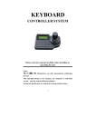
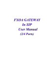
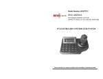
1
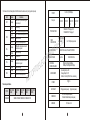
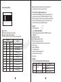
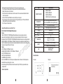
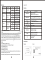
Connect Fiber to your Home Ethernet,LMedia TD Converter Family . O C IC ON R T EC H&T EL O T OP User's manual 10/100Mbps 10/100/1000Mbps 1000Mbps SFP slot Mode converter Version:3.0 Contents 1.10/100Mbps 1 6 2.10/100/1000Mbps 6 8 8 11 4.10/100/1000M SFP slot 11 13 5.1000M SFP slot 13 16 6.SFP-SFP 16 18 TD L , . CO P O T H& LE E O T C IC 3.1000Mbps N O TR Copyright statement This publication may not be reproduced as a whole or in part, any way whatsoever unless prior consent has been obtained from us. FCC warning The series media converter have been tested and found to comply with the limits for a Class A digital device, pursuant to Part 15 of the FCC Rules. These standards are designed to provide reasonable protection against harmful interference when these devices are operated in commercial environment These devices can use, generate and radiate radio frequency energy and may cause harmful interface to radio communications unless installed in accordance with this User's Guide. Operation of this device in a residential area is likely to cause harmful interface which will make the user responsible for the appropriate remedial action at his/her own expense. Standalone or Chassis design Auto Negotiation Speed, Half/Full Duplex TX port support Auto MDI/MDI-X Hot swap for chassis LFPT function(Link Fault Pass Through) Dual fiber or WDM selectable 1x9 or SFP module selectable Centralized Management(optional) LED indicators for working status diagnosis RoHS compliant CE mark Warning These are Class A products. In a domestic environment these products may cause radio interface in which case the user will need to consider adequate preventative measures. Package Content Thank you for purchasing our Ethernet Media Converter. Before you start installing the Media Converter, verify the following items in the package Media Converter User's Manual Power Adapter/Cord Warranty card H&T 1. MC-10/100 10/100Mbps Fast Media Converter The MC-10/100 10/100M fast Ethernet media converter is 10/100M auto-adaptation Ethernet fiber optic media converter, supporting the 10/100BASE-TX twisted-pair electrical signal and the 100BASE-FX optical signal interconversion. It expands the network transmitting range limit from the copper wire 100 meters to 2 kilometers (multi- model optical fiber), 120 kilometers (single model optical fiber), and can easily realize the link between HUB, SWITCH, the server, the terminal and long-distance terminal. 10/100M fast ethernet fiber optic media converter support plug and play, which means that it can work either independently or with others in a rack chassis, it has LFPT function(Link Fault Pass Through allowing the network manager to react to a broken link as soon as one occurs) and RoHS compliant. Key Features UTP to Fiber Media converter IC N O TR EC L E O OPT LED Status FEF Steady SPD FXLink/Act Off Steady Off Flashing Steady Indication Lit when local FX port receive signal from remote port NO Receiving When TP data transmission speed is 100M When TP data transmission speed is 10M Collision occurred Lit When fiber cable connection with remote device is good PWR Flash Steady FX data exchange The power is on TXLink/Act Steady Lit When fiber cable connection with remote device is good FDX 1 TD L , . CO LED Indication 1.1 Please refer to the following table for LED indication of media converter(external power) Flash Steady Off TP data exchange Connection in full duplex mode Connection in half-duplex mode 2 1.2 Please refer to the following table for LED indication of media converter( card type,internal power) LED Status FEF Steady SPD Off Flashing Lit When fiber cable connection with remote device is good PWR Flash Steady FX data exchange The power is on TXL Steady Lit When fiber cable connection with remote device is good FDX TP data exchange Connection in full duplex mode Connection in half-duplex mode Flash Steady Off Technical specifications TYPE STANDARD MC-10/100 -3M02 MC-10/100 -3S20 MC-10/100 -3S40 H ONIC LED INDICATIONS P O T & MC-10/100 -3S80 MC-10/100 -5S100 IEEE802.3 10BASE-T:IEEE802.3u 100BASE-TX/FX L TOE R ECT MAX. DISTANCE SC/FC/ST/ LC SC/FC/ST/ LC 10BASE-T:UTP Category 3,4,5 100BASE-TX:UTP Category 5 50/62.5/125µm multi-mode fiber 9 or 10/125µm single-mode FEF,SPD,FXLink/Act,TXLink/ACT,PWR,FDX 2km, 5km 20/40/60/80/120km FILTERING/ FORWARDING RATE 10Mbps:14,880pps/14,880pps 100Mbps5:148,800pps/148,800pps ENVIRONMENT Operating Temp:0~+60℃ Storage Temp20~+70℃ Relative humidity5%~90% non-condensing POWER 5V@ 1A NET WEIGHT DIMENSION EMISSION 3 SC/FC/ST/ LC TD L , . CO FIBER CONNCETIONS Steady SC/FC/ST/ LC TP CONNECTIONS Collision occurred Connection in half-duplex mode Off FXL Fiber port NO Receiving When TP data transmission speed is 100M When TP data transmission speed is 10M Off Steady RJ-45 x 1 (10/100Mbps) TP PORT Indication Lit when local FX port receive signal from remote port 0.45kgs(external power); 1kgs(internal power) 95X71X26mm(external power) 156mmX128mmX32mm(internal power) FCC Class A, CE 4 Notice: To activate above setting, please pay attention to set the DIP switch(1~6) to according position first, then turn on the power of media converter.. DIP switch setting for 10/100Mbps NO 1 2. MC-10/100/1000 10/100/1000Mbps Gigabit Media Converter The MC-10/100/1000 10/100/1000Mbps Ethernet fiber converter is designed to make fiber gigabit ethernet conversion between 10/100/1000Base-T/1000Base-SX/LX. It is Gigabit Ethernet converter application. In addition, the converter implements jumbo frame forwarding capability. The overall network flexibility is enhanced, and the network efficiency is also improved to accommodate and deliver high bandwidth applications. DIP 2 3 4 5 6 ■Set with DIP switch ■Set RJ45 port in full duplex/half duplex or auto-negotiation ■Set RJ45 port at 10Mbps、100Mbps or 10/100Mbps The DIP switch is marked 1-6 from left to right, the definition of the setting is as below: 1 OFF ON ON ON -ON 4 OFF ON 6 ON OFF DIP switch PIN 2 OFF OFF OFF ON ON 5 OFF OFF --- 3 OFF OFF ON OFF ON ---- Function Auto-negotiation(default setting) Force 100M full duplex Force 100M half duplex Force 10M full duplex Force 10M half duplex Mode setting store-and-forward mode(default setting) straightforward mode P O T H& LFPT function LFPT function open --- LFPT function close 5 LE E O T IC N O TR C TD L , . CO Key Features UTP to Fiber Media converter Comply with IEEE 802.3ab and IEEE802.3z Support mutual signal conversion between 10Base-T/100/1000Base-T adaptive and 1000Base-SX/LC Extend network span up to 80km 10/100/1000Mbps Auto MDI/MDI-X on UTP port Powered by AC/DC power adaptor Plug and play Standalone or Card module design,feasible to a 14/16 slots rack mount chassis Class 1 laser product Dual fiber or WDM selectable 1x9 or SFP module selectable Centralized or standalone management(optional) LED indicators for working ftatus diognisis RoHS compliant LED Indication 2.1.Please refer to the following table for LED indication(external power): Description Function Status LED PWR Power LED 100M Copper interface speed ON OFF ON Power is ON Power is OFF Copper port speed at 100M 6 FX/ACT Fiber interface link/action status 1000M Copper interface speed TP/ACT UTP interface link/action status Copper interface duplex mode FDX ON Blink OFF ON ON Blink OFF ON OFF Fiber link Success Fiber port transmit data IEEE802.3ab 1000Base-T , IEEE802.3z 1000Base-SX/LX Gigabit ethernet, IEEE802.1qVLAN, IEEE802.1p QoS,IEEE802.1d Spanning Tree Fiber link fail Copper port speed at 1000M Copper Fiber link Success Copper port transmit data Copper port link fail Full duplex Half duplex FXL 1000M TX RX Status Steady Steady Indication The Power is on Ethernet Speed is 100Mbps Steady A valid network connection established on Fiber port Off Steady FIBER CONNECTIONS Off Steady Steady H&T TYPE STANDARD LED INDICATIONS MAX.DISTANCE FIL TERING /FORWARDING RATE ENVIRONMENT POWER NET WELGHT DIMENSION EMISSION Technical Specifications MC-10/100/1000-8M05 MC-10/100/1000-3SXX/5SXX IEEE802.3 10Base-T Ethernet, IEEE802.3u 100Base-TX/FX Fast Ethernet, 7 O C C I N O R CT E L E O OPT No connection Ethernet Speed is 1000Mbps Ethernet Speed is 100Mbps Transmitting data Receiving data 10/100/1000BASE-T:UTP Category 5, 5E TP CONNECTIONS 2.2 Please refer to the following table for LED indication(internal power): LED PWR 100M RJ-45 port x 1 (10/100/1000 Mbps) SC/LC connector Fiber port x 1 (1000 Mbps) INTERFACE .,LTD 1000BASE-SX:62.5/ 125µm or 50/125µm Multi-mode fiber, SC/LC connector 1000BASE-LX:9or 10/125µm Single-mode fiber, SC/LC connector PWR ,100M;FXL,1000M,TX,RX; 550m/220m 10/20/40/80km 1000Mbps:1,488,000pps/1,488,000pps Operating Temp:0~+60℃ Storage Temp:-20~+70℃ Humlblty:5%~90% non-condensing input:220VAC/110VAC/-48VDC 50/60Hz output:5V 1A 0.45kgs(external power)1kgs(internal power) 95X71X26mm(external power) 156mmX128mmX32mm(internal power) FCC Class A, CE 3 MC-1000 1000/1000Mbps Gigabit Media Converter The MC-1000 1000Mbps media converter supports two types of media for network connection such as 1000BaseT and 1000Base-SX/LX fiber. The MC-1000 media converter is used to convert one type media signal to other type equivalent that allows two 8 types of segments to be connected easily and inexpensively. The Converter can be used as a standalone unit to the 2U 19" converter rack (up to 14 units) for use at a central wiring closet. Key Features UTP to Fiber Media converter Comply with IEEE 802.3ab and IEEE802.3z Support mutual signal conversion between 10Base-T/100/1000Base-T adaptive and 1000Base-SX/LC Extend network span up to 80km 1000Mbps Auto MDI/MDI-X on UTP port Powered by AC/DC power adaptor Plug and play Standalone or Card module design,feasible to a 14 slots rack mount chassis Class 1 laser product Dual fiber or WDM selectable 1x9 or SFP module selectable LED indicaforc for working status diagnosis RoHS compliant LED Indication 3.1 Please refer to the following tables for LED indication LED Function PWR Power LED 100M Copper interface speed FX/ACT Fiber interface link/ action status 1000M TP/ACT Status ON OFF ON ON Blink OFF ON ON Blink OFF H Copper interface speed UTP interface link/action Status 9 Technical specifications TYPE STANDARD TP CONNECTIONS R CT E L E Power is ON Power OFF Copper port speed at 100M Fiber link Success Fiber port transmit data Fiber link fail Copper port speed at 1000M Copper Fiber link Success Copper port transmit data Copper link fail ONIC MC-1000-8M05 MC-1000-3SXX/5SXX IEEE802.3ab 000BASE-T IEEE802.3ab 1000BASE-T IEEE802.3z 1000BASE-SX IEEE802.3z 1000BASE-LX RJ-45 port x 1 (1000 Mbps) SC/LC connector Fiber port x 1 (1000 Mbps) TD L , . CO INTERFACE TO P O &T Description Full duplex Half duplex ON OFF Copper interface duplex mode FDX 1000BASE-T:UTP Category 5, 5E FIBER CONNECTIONS 1000BASE-SX:62.5/125µm or 50/125µm Multi-mode fiber, SC/LC connector 1000BASE-LX:9or 10/125µm Single-mode fiber, SC/LC connector LED INDICATIONS MAX.DISTANCE FX,TX,FEF,RX,PWR,1000M 550m/220m 10/20/40/80km FIL TERING /FORWARDING RATE 1000Mbps:1,488,000pps/1,488,000pps Operating Temp:0~+60℃ ENVIRONMENT POWER NET WELGHT DIMENSION EMISSION Storage Temp:-20~+70℃ Humlblty:5%~90% non-condensing Input:220VSC/110VAC/-48VPC 0.45kgs output:5V 1A 95 x71 x 26mm(external) FCC Class A, CE Installation As with any electric device, you should place the equipment where it will not be subject to extreme temperatures, humidity, or electromagnetic interference. 10 Please follow the steps to install the media converter. This Converter is a plug-and-play device. 1. Turn off the power of the device/station in the network in which the media converterwill be installed. 2. Ensure that there is no activity in the network. 3. Attach fiber cable from the media converter to the fiber network. The fiber connectionsmust be Matched-Transmit socket to receive socket 4. Attach a UTP cable from the 100Base-Tx network to the RJ-45 port on the product 5. Connect the power cord to the media converter and check if the power LED lights up.The TP Link and FX link LEDs will light when all the cable connections are satisfactory. 6. Turn on the power of the device/station. ITEM SPECIFICATION ETHERNET STANDARDS IEEE802.3 10BASE-T IEEE802.3u 100BASE-TX IEEE802.3ab 1000Base-T IEEE802.3x Flow Control and Back pressure ETHERNET PORT CAT-5 (100/1000Mbps) unshielded twisted pair cable. Auto-crossover(MDI/MDI-X) and auto-negotiation support. MC-10/100/1000-SFP 10/100/1000Mbps SFP Media Converter Overview The MC-10/100/1000-SFP 10/100/1000M Gigabit Ethernet Media converter series are designed to meet the massive need for network deployment and able to extend a copper based network via fiber cable to a maximum 80km distance The MC-10/100/1000-SFP 10/100/1000M Gigabit Ethernet Media Converter series are fully compliant with IEEE802.3,IEEE802.3U, 10/100/1000Base-Tx, 1000Base-Fx, standards. It can be installed into to standard Converter chassis. The installation and operation procedures are simple straightforward. Operation status can be locally monitored through a set of diagnostic LED located in front panel. Features 10/100/1000Base-Tx to 1000Base-Fx Converter Standards: IEEE802.3,IEEE802.3U, 10/100/1000Base-Tx, 1000Base-Fx One 10/100/1000 Mbps Ethernet port One SFP slot for Gigabit Ethernet link Auto MDI/MDI-X support on RJ-45 port Flow control: IEEE802.3x flow control for duplex mode, Backpressure flow control flow control for half duplex mode. Status LEDs for easy monitoring of device’s status Extends distance up to 500m(1,650ft)for multi-mode fiber module,110km ((317,625ft) for single-mode fiber module (depends on SFP) IC N O TR TEMPERATURE C ELE H TO P O &T TD L , . CO FIBER PORT LEDS POWER DIMENSIONS SAFETY 4.Gigabit Ethernet Media Converter with One SFP slot SFP 3.3V with LC/SC connector PWR, 1000M, 100M, FX/ACT, TX/ACT, FDX External 5V 1A 95mmx71mmx26mm UL Operating:0 ~ 45℃( 32~113oF) Storage: -10 ~ 70℃ (14~158oF) HUMIDITY Operating: 10 ~ 90% (non-condensing) Storage: 10 ~ 90% (non-condensing) EMC FCC Part15 ( Class A) CE EMC (Class A) Product Illustrations Front panel Rear panel Technical Specifications 11 12 LED Indicators (depends on SFP) LED Function PWR Power LED 100M Copper interface speed FX/ACT Fiber interface link/ action status 1000M Copper interface speed TP/ACT UTP interface link/ action status FDX Copper interface duplex mode Status ON OFF ON ON Blink OFF ON ON Blink OFF ON OFF Description Specifications Power is ON Power OFF Copper port speed at 100M ITEM Fiber link Success Fiber port transmit data SPECIFICATION Fiber link fail Copper port speed at 1000M Copper port speed at 1000M Copper Fiber link Success Copper link fail Full duplex Full duplex ETHERNET PORT H&T 13 O OPT O C C I N O R CT E L E MC-1000-SFP 1000Mbps SFP Media Converter Overview The MC-1000-SFP 1000M Gigabit Ethernet Media converter series are designed to meet the massive need for network deployment and able to extend a copper based network via fiber cable to a maximum distance up to 80km. The MC-1000-SFP 1000M Gigabit Ethernet Media Converter series are fully compliant with IEEE802.3, IEEE802.3U, 1000Base-Tx, 1000Base-Fx, standards. It can be installed into to standard Converter chassis. The installation and operation procedures are simple straightforward. Operation status can be locally monitored through a set of diagnosti LED located in front panel. Features 10/100/1000Base-Tx to 1000Base-Fx Converter Standards: IEEE802.3,IEEE802.3U, 10/100/1000Base-Tx, 1000Base-Fx One 10/100/1000 Mbps Ethernet port One SFP slot for Gigabit Ethernet link Auto MDI/MDI-X support on RJ-45 port Flow control: IEEE802.3x flow control for duplex mode, Backpressure flow control flow control for half duplex mode. Status LEDs for easy monitoring of device’s status Extends distance up to 500m(1,650ft)for multi-mode fiber module,110km ((317,625ft) for single-mode fiber module FIBER PORT LEDS POWER DIMENSIONS SAFETY TEMPERATURE HUMIDITY EMC SPECIFICATION IEEE802.3ab 1000Base-T IEEE802.3x Flow Control and Back pressure CAT-5 (100/1000Mbps) unshielded twisted pair cable. Auto-crossover(MDI/MDI-X) and auto-negotiation support. .,LTD SFP 3.3V with LC/SC connector PWR, 1000M, 100M, FX/ACT, TP/ACT, FDX External 5V 1A 95mmx71mmx26mm UL Operating:0 ~ 45℃( 32~113oF) Storage: -10 ~ 70℃ (14~158oF) Operating: 10 ~ 90% (non-condensing) Storage: 10 ~ 90% (non-condensing) FCC Part15 ( Class A) CE EMC (Class A) Product Illustrations Front panel Rear panel 14 LED Indicators LED Function PWR Power LED 100M Copper interface speed FX/ACT Fiber interface link/ action status 1000M Copper interface speed TP/ACT UTP interface link/ action status FDX Copper interface duplex mode Status ON OFF ON OFF ON Blink OFF ON OFF ON Blink OFF ON OFF Power is ON Power OFF Copper port speed at 100M(cannot communicate) 5. MC-SFP-2.5G SFP-SFP Mode Converter 10/100M / 1.25G/2.5G Overview The MC-SFP-SFP-2.5G SFP-SFP Mode converters allow network operators to incorporate multiple fiber types within a network. The SFP-SFP Mode converter provides the ability to accomplish this by working with existing equipment and thus, eliminating replacement costs. With the flexibility to convert fiber between single-mode, multi-mode, single-strand and CWDM wavelengths, one can easily extend network range to reach more remote locations. Additionally, since the Mode Converter is an Industrial Equipment device, the unit operates in environments that demand extended operating temperatures. Copper port speed at 1000M Fiber link Success Fiber port transmit data Fiber link fail Copper port speed at 1000M Copper port speed at 100M Copper Fiber link Success Fiber port transmit data Copper port link fail Full duplex Half duplex P O T H& LE E O T Installation 1. Locate the Converter in a clean, flat and safe position that has easy access to AC power. 2. Insert a 3.3V SFP (Small Form-factor Pluggable) transceiver module connector into the SFP slot. 3. Remove the dust plugs from the SFP transceiver module. 4.Identify the signal transmission direction of the fiber-optic cable and the SFP transceiver module. Insert one end of the fiber-optic cable into the SFP transceiver module. 5. Insert the other end of the fiber-optic cable into a remote device. 6. Connect an Ethernet cable from a switch to this port. This port is auto- negotiating and auto-crossover. 7.Insert the power cable plug directly into its receptacle located at the back of the device. 8.Plug the power adapter into an available socket. 9.Check the LEDs as the device is powered on to verify that the Power LED is lit. If not, check that the power cable is correctly and securely plugged in. 15 Notices ■ This product is suitable for indoor usage application ■ Put on the dust cover of SFP transceiver when not in use ■ It's forbidden to stare at the TX fiber transmission end with naked eyes. Description IC N O TR LED Description TD L , . CO C Front View of Gigabit Converter P1 P2 PWR Lit when SFP1 connection is good. Lit when SFP2 connection is good. The indicator light means power work normally Features and Benefits Cost-effective and flexible Interchangeable SFP modules allow for multiple fiber mode/type conversion options (single mode, multi-mode, long haul, short haul, etc.) Extended operating temperatures 16 Multiple mounting options Compact size conserves space AC or DC power options Protocol-Independent Supports a full range of SFP modules offering various transmission speeds, from 10Mbps to 2.5Gbps Supports OC3,OC12,OC48 Maximizes network uptime SFP Modules are hot-Swappable; no need to power-down chassis when upgrading or trouble-shooting a single module Troubleshooting features: Diagnostic LEDs *Both SFPs used in the Mode Converter must support the same data rate. Technical Specifications The Converter conforms to the following standards: Includes two SFP ports Protocol-independent operation Converts between dissimilar fiber modes and Wavelengths Includes diagnostic LEDs Hot-swappable architecture Small Form Factor External 5VDC power Extended temperature range from 0℃ to 50℃ Can use all standard MSA compliant SFP devices Provides Extensive Diagnostic LED function 1000SX/LX TX Fiber RX Network RX 1000SX/LX TX Fiber RX Network H&T TX (P2 SFP) 1000SX/LX TX Fiber RX Network TX TX SFP-to-SFP Converter (P2 SFP) (P1 SFP) SFP-to-SFP Converter TD L , . CO RX TX RX TX 1000SX/LX TX Fiber RX Network Installing the Converter 1. Verify the AC-DC power adapter (for External Power Converter) and conforms to your country AC power requirement 2. Install the media cable for network connection 17 RX RX (P1 SFP) Basic Network connection 1 ONIC R ECT EL O T OP RX TX (P1 SFP) (P2 SFP) SFP-to-SFP Converter Basic Network connection 2 18 P O T H& LE E O T C IC N O TR TD L , . CO