1
USER’S MANUAL
F X 2 N - 6 4D P - M P r o f i b us -D P M a s t e r B l oc k
FX2N-64DP-M Profibus-DP Master Block
Foreword
• This manual contains text, diagrams and explanations which will guide the reader in the correct installation and operation of the FX2N-64DP-M Profibus-DP Master Block. It should be
read and understood before attempting to install or use the unit.
• Further information can be found in the FX2N Series Hardware Manual, FX Series Programming Manual, MELSEC ProfiMap Configuration System for Open Networks Software Manual and manual of Profibus-DP slave units.
• If in doubt at any stage of the installation of FX2N-64DP-M Profibus-DP Master Block always
consult a professional electrical engineer who is qualified and trained to the local and
national standards which apply to the installation site.
• If in doubt about the operation or use of FX2N-64DP-M Profibus-DP Master Block please
consult the nearest Mitsubishi Electric distributor.
• This manual is subject to change without notice.
FX2N-64DP-M Profibus-DP Master Block
FX2N-64DP-M PROFIBUS-DP
Master Block
USER’S MANUAL
Manual number : JY992D88001
Manual revision : B
Date
:March 2001
i
FX2N-64DP-M Profibus-DP Master Block
ii
FX2N-64DP-M Profibus-DP Master Block
FAX BACK
Mitsubishi has a world wide reputation for its efforts in continually developing and pushing back
the frontiers of industrial automation. What is sometimes overlooked by the user is the care
and attention to detail that is taken with the documentation. However,to continue this process
of improvement, the comments of the Mitsubishi users are always welcomed. This page has
been designed for you,the reader,to fill in your comments and fax them back to us. We look
forward to hearing from you.
Fax numbers:
Your name....................................................
Mitsubishi Electric....
.....................................................................
America
(01) 847-478-2283
Your company ..............................................
Australia
(02) 638 -7072
.....................................................................
Germany
(0 21 02) 4 86-1 12
Your location: ...............................................
South Africa
(0 27) 11 444-0223
.....................................................................
United Kingdom
(01707) 278-695
Please tick the box of your choice
¨Minor damage
¨Unusable
Will you be using a folder to store the manual?
¨Yes
¨No
What do you think to the manual presentation?
¨Tidy
¨Unfriendly
¨Not too bad
¨Unusable
What condition did the manual arrive in?
Are the explanations understandable?
¨Good
¨Yes
Which explanation was most difficult to understand: ..................................................................
....................................................................................................................................................
¨Yes
Are there any diagrams which are not clear?
¨No
If so,which:..................................................................................................................................
What do you think to the manual layout?
¨Good
¨Not too bad
¨Unhelpful
If there one thing you would like to see improved,what is it?......................................................
....................................................................................................................................................
....................................................................................................................................................
Could you find the information you required easily using the index and/or the contents,if possible please identify your experience: ...........................................................................................
....................................................................................................................................................
....................................................................................................................................................
....................................................................................................................................................
....................................................................................................................................................
Do you have any comments in general about the Mitsubishi manuals? .....................................
....................................................................................................................................................
....................................................................................................................................................
....................................................................................................................................................
....................................................................................................................................................
Thank you for taking the time to fill out this questionnaire. We hope you found both the product
and this manual easy to use.
iii
FX2N-64DP-M Profibus-DP Master Block
iv
FX2N-64DP-M Profibus-DP Master Block
Guidelines for the Safety of the User and Protection of the FX2N-64DP-M
Profibus-DP Master Block
This manual provides information for the use of the FX2N-64DP-M Profibus-DP Master Block.
The manual has been written to be used by trained and competent personnel. The definition of
such a person or persons is as follows;
a) Any engineer who is responsible for the planning, design and construction of automatic
equipment using the product associated with this manual should be of a competent
nature, trained and qualified to the local and national standards required to fulfill that
role. These engineers should be fully aware of all aspects of safety with regards to
automated equipment.
b) Any commissioning or service engineer must be of a competent nature, trained and
qualified to the local and national standards required to fulfill that job. These engineers
should also be trained in the use and maintenance of the completed product. This
includes being completely familiar with all associated documentation for the said
product. All maintenance should be carried out in accordance with established safety
practices.
c) All operators of the completed equipment should be trained to use that product in a safe
and co-ordinated manner in compliance to established safety practices. The operators
should also be familiar with documentation which is connected with the actual operation
of the completed equipment.
Note : Note: the term ‘completed equipment’ refers to a third party constructed device which
contains or uses the product associated with this manual.
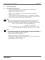
Notes on the Symbols Used in this Manual
At various times through out this manual certain symbols will be used to highlight points of
information which are intended to ensure the users personal safety and protect the integrity of
equipment. Whenever any of the following symbols are encountered its associated note must
be read and understood. Each of the symbols used will now be listed with a brief description of
its meaning.
Hardware Warnings
1) Indicates that the identified danger WILL cause physical and property damage.
2) Indicates that the identified danger could POSSIBLY cause physical and property
damage.
3) Indicates a point of further interest or further explanation.
Software Warnings
4) Indicates special care must be taken when using this element of software.
5) Indicates a special point which the user of the associate software element should
be aware of.
6) Indicates a point of interest or further explanation.
v
FX2N-64DP-M Profibus-DP Master Block
• Under no circumstances will Mitsubishi Electric be liable responsible for any consequential
damage that may arise as a result of the installation or use of this equipment.
• All examples and diagrams shown in this manual are intended only as an aid to
understanding the text, not to guarantee operation. Mitsubishi Electric will accept no
responsibility for actual use of the product based on these illustrative examples.
• Owing to the very great variety in possible application of this equipment, you must satisfy
yourself as to its suitability for your specific application.
vi
FX2N-64DP-M Profibus-DP Master Block
Table of Contents
Guideline of Safety...............................................................................v
1. Introduction............................................................................................1-1
1.1 Features of the 64DP-M ...................................................................................... 1-1
1.2 External Dimensions and Each part Name.......................................................... 1-2
1.2.1 Pin configuration of Profibus-DP Connector.............................................................. 1-3
1.3 System Configuration .......................................................................................... 1-4
1.3.1 Applicable Profibus-DP Network ............................................................................... 1-4
1.3.2 Applicable Programmable Controller......................................................................... 1-9
1.4 Communication Time........................................................................................... 1-9
1.4.1 Polling Cycle Time................................................................................................... 1-10
2. Wiring and Mounting .............................................................................2-1
2.1 Mounting .............................................................................................................. 2-1
2.1.1 Arrangements ............................................................................................................ 2-1
2.1.2 Mounting.................................................................................................................... 2-1
2.2 Wiring .................................................................................................................. 2-2
2.2.1
2.2.2
2.2.3
2.2.4
2.2.5
Caution ...................................................................................................................... 2-2
Wiring ........................................................................................................................ 2-3
Wiring of Power Supply ............................................................................................. 2-3
Wiring of Profibus-DP ................................................................................................ 2-4
Terminating resistor................................................................................................... 2-4
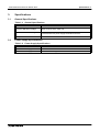
3. Specifications ........................................................................................3-1
3.1 General Specifications......................................................................................... 3-1
3.2 Power Supply Specifications ............................................................................... 3-1
3.3 Performance Specifications ................................................................................. 3-2
vii
FX2N-64DP-M Profibus-DP Master Block
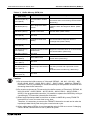
4. Allocation of Buffer Memories (BFMs)...................................................4-1
4.1
4.2
4.3
4.4
4.5
Buffer Memories (BFM) Lists ............................................................................... 4-1
Communication Status Flags <BFM #0, BFM #1> (Read Only) .......................... 4-3
Communication Control Flags <BFM #2> (Read / Write) .................................. 4-10
Communication Stop Timer Setting <BFM #9> (Read / Write).......................... 4-12
Slave Data Consistency Mode <BFM #10 ~ #22>............................................. 4-13
4.5.1
4.5.2
4.5.3
4.5.4
4.6
4.7
4.8
4.9
4.10
4.11
4.12
4.13
4.14
4.15
Slave Data Consistency Mode Process .................................................................. 4-14
Output Data Send Request Flags <BFM #11 ~ #14> (Read / Write) ...................... 4-15
Output Data Sending End Flags <BFM #15 ~ #18> (Read Only) ........................... 4-15
Output Data Send Error Flags <BFM #19 ~ #22> (Read / Write)............................ 4-16
Master Reset <BFM #27> (Read / Write) .......................................................... 4-18
Initial Data Set <BFM #28> (Read / Write) ........................................................ 4-18
Master Status <BFM #29> (Read Only) ............................................................ 4-19
Module ID code <BFM #30> (Read Only) ......................................................... 4-19
Number of Used Input Byte <BFM #37> (Read Only) ....................................... 4-19
Number of Allocated Slave <BFM #38> (Read Only) ........................................ 4-19
Operation Service Mode <BFM #39> (Read Only)............................................ 4-19
Input Slave State <BFM #40 ~ #43> (Read Only) ............................................. 4-20
Output Slave State <BFM #44 ~ #47> (Read Only) .......................................... 4-20
Input Data Area <BFM #100 ~ #1059> (Read Only) ......................................... 4-21
4.15.1 Normal Service Mode <Mode Switch: 0> ................................................................ 4-21
4.15.2 Extended Service Mode <Mode Switch: E> ............................................................ 4-23
4.16 Output Data Area <BFM #1060 ~ #2019> (Read / Write) ................................. 4-24
4.16.1 Normal Service Mode <Mode Switch: 0> ................................................................ 4-24
4.16.2 Extended Service Mode <Mode Switch: E> ............................................................ 4-26
4.17 Address Information Area <BFM #2020 ~ #2139> (Read Only)........................ 4-27
4.18 Communication Trouble Area <BFM #2140 ~ #2179> (Read Only).................. 4-29
4.18.1 Fixed Type and Ring Type methods ....................................................................... 4-30
4.18.2 Error codes .............................................................................................................. 4-31
4.19 Expansion Communication Trouble Area <BFM #2196 ~ #2210> (Read Only) 4-34
4.19.1
4.19.2
4.19.3
4.19.4
4.20
4.21
4.22
4.23
4.24
BFM #2196 .............................................................................................................. 4-35
BFM #2197 .............................................................................................................. 4-36
BFM #2198 ~ #2210................................................................................................ 4-36
Example of the Expansion Communication Trouble Area ....................................... 4-40
Slave Diagnostic Status Cancel <BFM #2180> (Read / Write) ......................... 4-41
Global Control Area <BFM #2181> (Read / Write) ............................................ 4-42
Information Dwell Time Setting <BFM #2184> (Read / Write)........................... 4-43
Slave Status Area <BFM #2212 ~ #2216> (Read Only).................................... 4-43
Input / Output Start Address Area <BFM #2228 ~ #2347>
(Extended Service Mode Only) <Read Only> ................................................... 4-44
5. Global Control .......................................................................................5-1
5.1 SYNC and UNSYNC Global Control ................................................................... 5-1
5.2 FREEZE and UNFREEZE Global Control ........................................................... 5-1
5.3 Global Control Service Process........................................................................... 5-2
6. Mode and Displayed Station Address ...................................................6-1
6.1 Mode.................................................................................................................... 6-1
6.1.1 Mode Setting Switch.................................................................................................. 6-1
6.2 Displayed Station Address .................................................................................. 6-2
viii
FX2N-64DP-M Profibus-DP Master Block
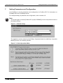
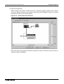
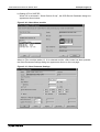
7. Setting Parameters and Configuration ..................................................7-1
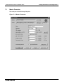
7.1 Master Parameter ................................................................................................ 7-2
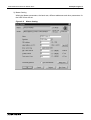
7.2 Bus Parameter..................................................................................................... 7-3
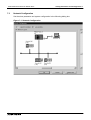
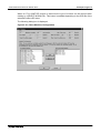
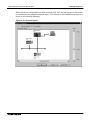
7.3 Network Configuration ......................................................................................... 7-4
8. Example Program..................................................................................8-1
8.1
8.2
8.3
8.4
System Configuration .......................................................................................... 8-1
Contents of Operation ......................................................................................... 8-1
Parameter Setting................................................................................................ 8-2
Example Program .............................................................................................. 8-11
9. Diagnostics ............................................................................................9-1
9.1
9.2
9.3
9.4
Preliminary Checks.............................................................................................. 9-1
Check the Status of the LEDs for the 64DP-M .................................................... 9-2
Self Diagnostic of the 64DP-M ............................................................................ 9-4
Diagnostic Information and Error Code ............................................................... 9-4
Appendix A:
Further Information Manual List ............................................................... A-1
ix
FX2N-64DP-M Profibus-DP Master Block
x
FX2N-64DP-M Profibus-DP Master Block
1.
Introduction
1.1
Features of the 64DP-M
Introduction 1
The FX2N-64DP-M Profibus-DP Master Block (hereafter called “64DP-M”) is a “Class 1” master
for the Profibus-DP network (hereafter called “DP-network”). The FX2N series programmable
controller by connecting 64DP-M can read input data from the Profibus-DP slave (hereafter
called “DP-slave”), and write output data to the DP-slave.
• Controlled maximum slaves:
A 64DP-M can control a maximum of 60 slaves using repeaters on the DP-network.
For system configuration of the DP-network, refer to section 1.3.
• Configuration setting:
Configuration of the 64DP-M can be set easily by MELSEC ProfiMap configuration software
(V3.00 or more). For MELSEC ProfiMap configuration software (hereafter called “ProfiMap),
refer to MELSEC ProfiMap Configuration System for Open Networks Software Manual. For
choosing module type, refer to Appendix B.
• Communication:
The 64DP-M supports 9.6k, 19.2k, 93.75k, 187.5k, 500k, 1,500k, 3M, 6M and 12Mbps.
The 64DP-M can be connected to a Profibus-DP network by a standard 9-pin D-SUB
connector and shielded twisted pair cable complying with EN50170. See chapter 2.
• Global control:
The 64DP-M supports Sync global control, Unsync global control, Freeze global control and
Unfreeze global control.
1-1
FX2N-64DP-M Profibus-DP Master Block
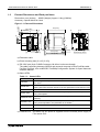
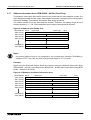
External Dimensions and Each part Name
Dimensions: mm (inches)
MASS (Weight): Approx. 0.4kg (0.88 lbs)
Accessory: Special block No. label
b)
i)
FX2N-64DP-M
b)
POWER
l)
PROFIBUS-DP
5 (0.20")
MODE
0 ONLINE1
1 PRM SET
2 TEST
E ONLINE2
RS-232-C
g)
PROFIBUS-DP
h)
TEST
B6
B5
B4
B3
ST NO.
B2
B1
B0
f)
RUN
SD/RD
TOKEN
READY
FROM/TO
PRM SET
RSP ERR
FAULT
45
89A
RS-232-C
FX2N-64DP-M
POWER
MODE
23
67
b)
c)
e)
24-
RUN
SD/RD
TOKEN
READY
FROM/TO
PRM SET
RSP ERR
FAULT
j) k)
b)
01
EF
d)
24+ FG
a)
87 (3.43")
85 (3.35")
5 (0.20") c)
5 (0.20")
90 (3.54")
5 (0.20")
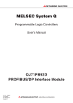
Figure 1.1: External Dimensions
BCD
1.2
Introduction 1
TEST
B6 S
B5 T
B4
B3 N
B2 O.
B1
B0
g)
h)
95.5 (3.76")
102 (4.02")
g)
9 (0.35")
b)
Remove Top Cover
a) Extension cable
b) Direct mounting hole (2-∅4.5 (0.18"))
c) RS-232C port (9-pin D-SUB Connector: #4-40unc inch screw thread)
The cable connecting between 64DP-M and personal computer is Blue ProfiCab cable.
For Blue ProfiCab, refer to MELSEC ProfiMap Configuration System for Open Networks
Software Manual.
d) Status LEDs
Table 1.1: Status LEDs
LED Name
Description
RUN LED
ON: During normal operation
OFF: Error
SD/RD LED
Flashes during communication with slave on the Profibus network. The
flashing interval is the time interval of the bus parameter’s Data Control Time.
TOKEN LED
ON when token is maintained.
READY LED
ON when the Profibus-DP network subscription preparation is completed and
during subscription.
FROM/TO LED
ON when a FROM/TO instruction from the programmable controller is
operating.
PRM.SET LED
ON (PARAMETER SET) when in the parameter setting mode. When flashing
during normal operation, the parameter is not written.
RSP ERR LED
ON when a communication error occurs.
FAULT LED
ON when an error occurs.
e) POWER LED: ON when 24V DC power is supplied form the external power supply or
FX2N series PLC.
1-2
FX2N-64DP-M Profibus-DP Master Block
Introduction 1
f) TEST LED and STATION LED
Table 1.2: TEST LED and STATION LED
LED Name
Description
TEST LED
ON when self-diagnosis is executing.
STATION
LED
Displays the station address during normal operation. (Binary) Displays the test
type during self-diagnosis. (B0 ~ B6)
g) Hook for mounting DIN rail
h) PROFIBUS-DP port (9-pin D-SUB Connector: #4-40unc inch screw thread)
i) Groove for mounting DIN rail (DIN 46277<DIN rail width: 35mm (1.38")>)
j) DC power supply terminals (screws terminal: M3)
k) Mode setting switch (Default setting: “0”) For mode, refer to Chapter 4.
Table 1.3: Mode Switch
Switch No.
Mode
0
ONLINE1 (Normal service mode)
1
PRM SET (Parameter setting mode)
2
TEST (Self diagnostic mode)
3~D
Cannot use
E
ONLINE2 (Extended service mode)
F
Cannot use
l) port for extension cable
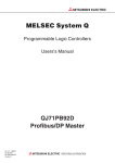
Pin configuration of Profibus-DP Connector
The connector is a 9-pin D-SUB (#4-40unc inch screw thread) type, the pin configuration is
shown below.
Figure 1.2: Pin Layout of Profibus-DP Connector
5
Table 1.4: Profibus-DP Connector Pin
Configuration
Meaning
RXD/TXD-P Receive/transmit-Data-P
5
DGND
Data Ground
6
VP
Voltage-Plus
8
RXD/TXD-N Receive/transmit-Data-N
1, 2, 4,
7, 9
7
3
8
3
2
Signal
Name
1
4
9
Pin No.
6
1.2.1
Assigned
Not assigned
NC
Pin not assigned
1-3
FX2N-64DP-M Profibus-DP Master Block
1.3
System Configuration
1.3.1
Applicable Profibus-DP Network
Introduction 1
• The maximum number of slaves that can be connected to a 64DP-M is 60.
• Number that can be connected for 1 segment
Masters + slaves + repeaters ≤ 32 units
• Number of units that can be connected to the entire network using repeaters.
Masters + slaves ≤ 126 units
• Communications can be conducted via a maximum of 3 repeaters from an arbitrary
master or arbitrary slave to an arbitrary master or arbitrary slave. However, the whole
network can contain more than 3 repeaters. (See note above.)
Note;
When using a slave with expansion diagnostic information of more than 32 bytes, the
network will be limited. Maximum expansion diagnostic information data length is the
smaller of the value obtained from a slave address by the following equation or 244 bytes.
Maximum expansion diagnostic information data length (bytes)
= [12600 ÷ N*1 - 10] or [244]
*1 The value of N is the smaller of the value obtained by the following equation or 300.
N = [(Max. slave address value - Min. slave address value + 1) × 5] or [300]
Note:
It is not possible to communicate normally with the slave when the maximum diagnosis
information data length (Max_Diag_Data_Len) has been decided by the slave’s GSD file is
larger than the value obtained by the above expression.
In this case, please try the following things.
1) Make the slave address consecutive number if possible.
2) Change setting so that this value may become small if the maximum diagnosis information data length on the slave side can be set.
3) Reduce connected number of the slave.
1-4
FX2N-64DP-M Profibus-DP Master Block
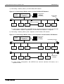
Introduction 1
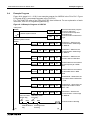
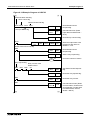
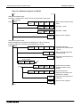
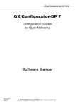
1) Connecting 1 master (class 1) on the Profibus-DP network.
Figure 1.3: Connecting 1 Master (class 1) on the Profibus-DP Network
FX2N
Series
FX2N-64DP-M
(Master of Class 1)
No.40 *1
Configuration
Software
(ProfiMap)
Terminating
resistor
Terminating resistor
Profibus-DP Network
Slave
No.1
Slave
No.2
Slave
No.3
Slave
No.29
Slave
No.30
Slave
No.31
*1 In this system configuration, this 64DP-M can connect maximum 31 slaves. As the total
units (masters + slaves + repeaters) is 32 units when DP-network is 1 segment.
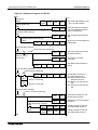
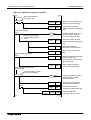
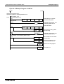
2) Connecting 1 master (class 1) and 1 repeater on the Profibus -DP network.
Figure 1.4: Connecting 1 Master (class 1) and 1 Repeater on the Profibus -DP Network
FX2N
Series
FX2N-64DP-M
(Master of Class 1)
No.80 *1
Configuration
Software
(ProfiMap)
Terminating resistor
Terminating resistor
Slave
No.1
Slave
No.2
Slave
No.3
Slave
No.29
Slave
No.30
Slave
No.31
Slave
No.32
Slave
No.33
Slave
No.59
Slave
No.60
Repeater
Profibus-DP
Network
*1 In this system configuration, this 64DP-M can connect maximum 60 slaves, as a
repeater is used.
1-5
FX2N-64DP-M Profibus-DP Master Block
Introduction 1
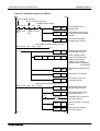
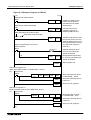
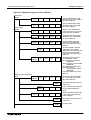
3) Connecting 1 master (class 1) and 3 repeaters on the Profibus -DP network.
Figure 1.5: Connecting 1 master (class 1) and 3 Repeaters on the Profibus -DP Network
FX2N
Series
FX2N-64DP-M
(Master of Class 1)
No.70 *1
Configuration
Software
(ProfiMap)
Terminating resistor
Terminating resistor
Slave
No.1
Repeater
Slave
No.45
Slave
No.2
Slave
No.3
Slave
No.17
Slave
No.18
Slave
No.19
Slave
No.20
Slave
No.34
Slave
No.35
Slave
No.36
Slave
No.37
Slave
No.43
Slave
No.44
Slave
No.46
Slave
No.47
Slave
No.59
Slave
No.60
Repeater
Profibus-DP
Network
Repeater
*1 Communications can be conducted via a maximum of 3 repeaters from an arbitrary
master or arbitrary slave to an arbitrary master or arbitrary slave. However, the whole
network can contain more than 3 repeaters.
1-6
FX2N-64DP-M Profibus-DP Master Block
Introduction 1
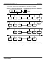
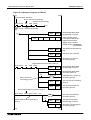
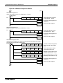
4) Connecting 126 stations (3 masters + 60 slaves or more) on the Profibus-DP network.
Please see “Note” on the next page.
Figure 1.6: Connecting 126 Stations (3 Masters + 60 Slaves or More) on the Profibus-DP
Network
FX2N-64DP-M
(Master of Class 1)
No.124 *1
FX2N
Series
FX2N-64DP-M
(Master of Class 1)
No.125 *2
FX2N
Series
FX2N-64DP-M
(Master of Class 1)
No.126 *3
FX2N
Series
Terminating
resistor
Terminating resistor
Repeater
Slave No.1
Slave No.14
Slave No.15
Slave No.17 Slave No.18
Profibus-DP
Network
Repeater
Slave No.19 Slave No.20
Slave No.55 Slave No.56
Repeater
Repeater
Slave No.57
Slave No.86
Slave No.107
Slave No.84 Slave No.85
Slave No.108
Slave No.123
*1 This 64DP -M has total 38 slaves (No.1 ~ 14, 19, 85 ~ 107).
*2 This 64DP-M has total 32 slaves (No.15 ~ 17, 56 ~ 84)
*3 This 64DP-M has total 53 slaves (No.18, 20 ~ 55, 108 ~ 123)
1-7
FX2N-64DP-M Profibus-DP Master Block
Introduction 1
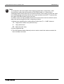
Note
In Configuration that use multiple master stations (multimaster configuration), when
reconnecting a cable after disconnecting a PROFIBUS cable for 1 master that is
exchanging data at allow baud rate, the communications of the master for which the cable
is not disconnected could stop and the slave output could be turned OFF. To prevent this,
the master PROFIBUS cable must be secured.
In addition, there is a high possibility that the above phenomena can be avoided if care is
taken with the following points when configuring a system.
1) Set the slave watchdog timer setting value to larger than (TTr × G)/BR. However,
TTr: Target token rotation time (Unit: Bit Time)
G:
Gap update factor
BR: Baud rate (Unit: bps)
2) Use a high baud rate.
3) The HSA (Highest Station Address) value is made to match the maximum station No.
that is actually connected.
1-8
FX2N-64DP-M Profibus-DP Master Block
1.3.2
Introduction 1
Applicable Programmable Controller
For setting up a system, the 64DP-M can be connected directly to the FX 2N series
programmable controller’s extension port, or to any other extension unit / block’s right side
extension port.
The 64 DP-M occupies 8 points of I/O on the FX2N’s expansion bus. The 8 points can be
allocated from either inputs or outputs. The maximum I/O for a FX2N system is 256 I/O.
Table 1.5: Applicable Programmable Controller
Programmable Controller Type
FX2N series
1.4
Version
From first product
(All versions)
Communication Time
The communication time is the data exchange time between FX 2N series programmable
controller and slave on the Profibus-DP. This communication time can be requested by the
expression below.
Communication time = Total of polling cycle time*1 for each slave + (2 × Scan time*2)
*1 The polling cycle time is a data update cycle time between 64DP-M and slave on the DPnetwork. For how to obtain the polling cycle time, refer to subsection 1.4.1.
*2 The scan time can be checked with D8010 ~ D8012 of the programmable controller.
Note;
The polling cycle time and FROM/TO instruction are operated asynchronously. If data is
written to the 64DP-M in the polling cycle, this data will move to the system area on the next
polling cycle.
1-9
FX2N-64DP-M Profibus-DP Master Block
1.4.1
Introduction 1
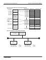
Polling Cycle Time
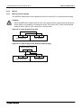
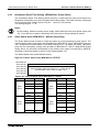
An explanation of the polling cycle time for one master is given in figure 1.6. In this example
there are 3 slaves. The polling cycle time is the larger of:
Number of slaves
Polling cycle time = the higher value of [MSI] or [
{Pt (Slave (i)) + Tsdi (M)} + Lr]
Σ
i=1
Explanation of MSI, Pt (Slave (i)), Treq (i), Max Tsdr (i), Tres (i), Tsdi (M), Lr see following table.
Table 1.6: Wording for Polling Cycle Time
Wording
Description
Pt (Slave (i))
The polling time of the slave = Treq (i) + Max Tsdr (i) + Tres (i)
Treq (i)
The request transmission time of the slave =
(number of output bytes to this slave + 9) × 11) / baud rate
Max tsdr (i)
Response time of the slave =
(This value is recorded in this slave GSD file.) / baud rate
Tres (i)
Response transmission time of the slave (Number of input bytes from this slave + 9) × 11) / baud rate
Tsdi (M)
Processing time of master request/response =
(This value is recorded in this slave GSD file.) / baud rate
Lr
Data refresh time = Max. 260 ms + 5 ms × number of slaves
MSI
Minimum slave interval is set in the configuration software (ProfiMap).
1-10
FX2N-64DP-M Profibus-DP Master Block
Introduction 1
Figure 1.7: Polling Cycle Time
Time
Programmable
controller
TO instruction
FROM instruction
BFM of the
64DP-M
System Data
Area for
communication
in 64DP-M
Slave No.1
Slave No.2
Slave No.3
Q
Lr
R
S
Q
T
Pt (Slave 1)
R
S
Pt (Slave 2)
Q
T
R
S
Pt (Slave 3)
T
Polling cycle time*1
Q This time is “Treq” for each slave.
R This time is “Maximum Tsdr” for each slave.
S This time is “Tres” for each slave.
T This time is Tsdi(M)
*1 The polling cycle time is the larger of the value obtained from the equation on the prior
page or the MSI. MSI (Minimum slave interval) is set in the configuration software
(ProfiMap).
Note;
FROM/TO instruction and the polling cycle are asynchronous.
1-11
FX2N-64DP-M Profibus-DP Master Block
Introduction 1
MEMO
1-12
FX2N-64DP-M Profibus-DP Master Block
2.
Wiring and Mounting
2.1
Mounting
2.1.1
Arrangements
Wiring and Mounting 2
The 64DP-M connects on the right side of an FX2N series main unit or extension unit/block
(include special function block). For further information of mounting arrangements, refer to
FX2N Series Hardware Manual.
2.1.2
Mounting
Mounting method of the 64DP-M is DIN rail mounting or direct wall mounting.
1) DIN rail mounting
• Align the upper side of the DIN rail mounting groove of the 64DP-M with a DIN rail*1 (Q),
and push it on the DIN rail(R). See Figure 2.1.
• When removing the 64DP-M from the DIN rail, the hook for DIN rail is pulled (S), and the
64DP-M is removed (T). See Figure 2.2.
Figure 2.1: Attach to DIN Rail
Figure 2.2: Remove from DIN Rail
*1 Uses DIN 46277 <35mm (1.38")>
2) Direct mounting to back walls
The 64DP-M can be mounted with M4 screws by using the direct mounting holes.
An interval space between each unit of 1 ~ 2 mm is necessary.
2-1
FX2N-64DP-M Profibus-DP Master Block
2.2
Wiring
2.2.1
Caution
Wiring and Mounting 2
1) Do not lay signal cable near to high voltage power cable or house them in the same
trunking duct. Effects of noise or surge induction may occur. Keep signal cables a safe
distance of more than 100 mm (3.94") from these power cables.
2) Ground the shield wire or the shield of a shielded cable at one point on the programmable
controller. Do not, however, ground at the same point as high voltage lines.
3) Terminal screws of the 64DP-M are M3 (0.12"), therefore crimp style terminals (see
drawing) suitable for use with these screws should be fitted to the cable for wiring.
Figure 2.3: Crimp Terminals
6.2 mm (0.24" )
or less
For M3 (0.12")
For M3 (0.12")
6.2 mm (0.24")
or less
4) The terminal tightening torque is 0.5 ~ 0.8 Nm. Tighten securely to avoid malfunction.
5) Cut off all phases of power source before installation or performing wiring work in order to
avoid electric shock or damage of product.
6) Replace the provided terminal cover before supplying power and operating the unit after
installation or wiring work, in order to avoid electric shock.
2-2
FX2N-64DP-M Profibus-DP Master Block
2.2.2
Wiring
2.2.3
Wiring of Power Supply
Wiring and Mounting 2
The 64DP-M needs power to be supplied from an FX2N series PLC or external power supply.
Caution
When the 64DP-M is supplied with 24V DC from external power supply, this external power
supply needs to be started up at same time as the FX2N series PLC. If this external power
supply is late to start up, FX2N series PLC could be down.
Figure 2.4: Power Supply From PLC
24V
0V
+24V
FX2N Series PLC
-24V
FX2N-64DP-M
Figure 2.5: Power Supply From External Power Supply
External power supply
0V
24V
0V
FX2N Series PLC
24V
+24V
-24V
FX2N-64DP-M
2-3
FX2N-64DP-M Profibus-DP Master Block
2.2.4
Wiring and Mounting 2
Wiring of Profibus-DP
To connect the 64DP-M to a Profibus-DP network use only the Profibus connectors and
shielded twisted-pair cable complying with EN50170. For Profibus connectors see the Profibus
connector manual.
Figure 2.6: Wiring
For Profibus connection,
refer to Figure 2.7.
Shielded twisted-pair
cable complying with
EN50170 to Profibus-DP
network
External power supply or the
service power supply of PLC
FG
+24
-24
FX2N-64DP-M
Profibus-DP Master
Block
Grounding plate
Grounding
resistance of
100 Ω or less
(Class D)
RS-232C connector
for connecting
configuration software
(ProfiMap)
For noise prevention please attach at least 50 mm
(1.97") of the twisted-pair cable along the
grounding plate to which the ground terminal is
connected.
Figure 2.7: Profibus Connection
Shielded twisted-pair cable to
Profibus-DP network
FX2N-64DP-M Profibus-DP
Master Block
2.2.5
Terminating resistor
The units at each end of the Profibus-DP network must have a terminating resistor. This will
either be in the master or slave unit or in the Profibus connector.
However, the 64DP-M does not have a terminating resistance built-in.
2-4
FX2N-64DP-M Profibus-DP Master Block
3.
Specifications
3.1
General Specifications
Specifications 3
Table 3.1: General Specifications
Items
Description
General specifications excluding
Same as those of the main unit
Dielectric Withstand Voltage
3.2
Dielectric Withstand Voltage
500 V AC > 1 min.
tested between DC power supply terminals and earth
Complies With
UL508
Power Supply Specifications
Table 3.2: Power Supply Specifications
Items
Description
External Power Supply
250 mA at 24 V DC
Internal Power Supply
30 mA at 5 V DC supplied via extension cable
3-1
FX2N-64DP-M Profibus-DP Master Block
3.3
Specifications 3
Performance Specifications
Table 3.3: Performance Specifications
Item
Specifications
Transmission Type
Bus network
Unit type
Profibus-DP master Class 1
Transmission Data
(Maximum Exchanged Data
Length)
ONLINE1(Normal service mode): 32 bytes / slave
ONLINE2(Extended service mode): 244 byte/slave
Maximum Number of Repeaters
3 units
/ Network
Maximum Number of Stations /
Segment
32 stations (See Note 1)
Maximum Number of Slaves /
Master
60 slaves (See Note 1)
Number Connection of Nodes
(Number of Repeaters)
32, 62 (1), 92 (2), 126 (3) (See Note 1)
9.6k, 19.2k,
93.75k
Supported
Baud Rates 187.5k
500k
(bps) and
Bus Length 1.5 M
3M, 6M, 12M
PNO ID
Connector
See Note 1
1,200 m (3,937') / segment
1,000 m (3,281') / segment
400 m (1,312') / segment
See Note 2
200 m (656') / segment
100 m (328') / segment
F264 H
RS-232C
Port for download configuration
(9 pin D-SUB Connector: #4-40unc inch screw thread)
Profibus-DP
Network
Port for Profibus-DP network
(9 pin D-SUB Connector: #4-40unc inch screw thread)
Synchronization
Synchronization, unsynchronization, freeze and unfreeze modes
shall be supported.
Terminal Resistor
Not built in.
Number of occupied I/O points
8 points taken from the programmable controller extension bus (can
be either input or output)
Applicable Programmable
Controller
FX2N Series
LED
indicators
POWER LED
ON when 24V DC power is supplied form the PLC or external power
supply.
RUN LED
ON: During normal operation
OFF: Error
SD / RD LED
Flashes during communication with slave on the Profibus network.
The flashing interval is the time interval of the bus parameter’s Data
Control Time.
TOKEN LED
ON when token is maintained.
READY LED
ON when the Profibus-DP network subscription preparation is
completed and during subscription.
FROM/TO LED
ON when a FROM/TO instruction from the programmable controller
is operating.
3-2
FX2N-64DP-M Profibus-DP Master Block
Specifications 3
Table 3.3: Performance Specifications
Item
LED
indicators
Specifications
PRM.SET LED
ON (PARAMETER SET) when in the parameter setting mode. When
flashing during normal operation, the parameter is not written.
RSP ERR LED
ON when a communication error occurs.
FAULT LED
ON when an error occurs.
TEST LED
ON when self-diagnosis is executing.
STATION LED
Displays the station address during normal operation.(Binary)
Displays the test type during a self-diagnosis. (B0 to B6)
Note 1;
When using a slave with expansion diagnostic information of more than 32 bytes, the
network will be limited. Maximum expansion diagnostic information data length is the
smaller of the value obtained from a slave address by the following equation or 244 bytes.
Maximum expansion diagnostic information data length (bytes)
= [12600 ÷ N*1 - 10] or [244]
*1 The value of N is the smaller of the value obtained by the following equation or 300.
N = [(Max. slave address value - Min. slave address value + 1) × 5] or [300]
It is not possible to communicate normally with the slave when the maximum diagnosis
information data length (Max_Diag_Data_Len) has been decided by the slave’s GSD file is
larger than the value obtained by the above expression.
In this case, please try the following things.
1) Make the slave address consecutive number if possible.
2) Change setting so that this value may become small if the maximum diagnosis information data length on the slave side can be set.
3) Reduce connected number of the slave.
Note 2;
Length that the bus can be expanded by using repeaters.
Maximum Bus Length = (“Number of repeaters” + 1) × “Bus Length / segment”
Table 3.4: Maximum Bus Length and Baud Rate
Baud Rate (bps)
Maximum Bus Length
No repeater
1 repeater
2 repeaters
3 repeaters
9.6k, 19.2k, 93.75k 1,200 m (3,937')
2,400 m (7,874')
3,600 m (11,811')
4,800 m (15,748')
187.5k
1,000 m (3,281')
2,000 m (6,562')
3,000 (9,843')
4,000 m (13,123')
500k
400 m (1,312')
800 m (2,625')
1,200 m (3,937')
1,600 m (5,249')
1.5 M
200 m (656')
400 m (1,312')
600 m (1,969')
800 m (2,625')
3M, 6M, 12M
100 m (328')
200 m (656')
300 m (984')
400 m (1,312')
3-3
FX2N-64DP-M Profibus-DP Master Block
Specifications 3
MEMO
3-4
FX2N-64DP-M Profibus-DP Master Block
Allocation of Buffer Memories (BFMs) 4
4.
Allocation of Buffer Memories (BFMs)
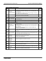
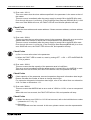
4.1
Buffer Memories (BFM) Lists
Table 4.1: Buffer Memory (BFM) List
BFM No.
(Hex code)
BFM #0 (000 H)
BFM #1 (001 H)
Name
Communication Status
Flags
BFM #2 (002 H)
Communication Control
flags
BFM #3 (003 H) ~
#8 (008 H)
Not used
BFM #9 (009 H)
Communication Stop
Timer Setting
BFM #10 (00A H)
Slave Data Consistency
Mode
Description
Read only
Read only
Read / Write
Read / Write
BFM #11 (00B H) ~ #14 Output Data Send
(00E H)
Request Flags
BFM #15 (00F H) ~ #18 Output Data Sending End
(012 H)
Flags
Read only
BFM #19 (013 H) ~ #22 Output Data Send Error
(016 H)
Flags
Read / Write
BFM #23~
#26 (01A H)
Not used
BFM #27 (01B H)
Master Reset
Read / Write
BFM #28 (01C H)
Initial Data Set
The initial data writing / reading instruction signal
BFM #29 (01D H)
Master Status
Read only
BFM #30 (01E H)
Module ID Code
K7060 (Read only)
BFM #31 (01F H) ~
#36 (024 H)
Not used
BFM #37 (025 H)
Number of Used Input
Byte
BFM #38 (026 H)
Number of Allocated Slave
BFM #39 (027 H)
Operation mode
Read only
BFM #40 (028 H) ~ #43
Input Slave State
(02B H)
BFM #44 (02C H) ~
#47 (02F H)
Output Slave State
BFM #48 (030 H) ~
#99 (063 H)
Not used
BFM #100 (064 H) ~
#1059 (423 H)
Input Data Area
This is the area that stores the input data from
the slave. (Read only)
BFM #1060 (424 H) ~
#2019 (7E3H)
Output Data Area
This is the area that stores the output data to the
slave. (Read / Write)
BFM #2020 (7E4 H) ~
#2139 (85BH)
Address Information Area
This is the area that shows the slave address
and I/O data length. (4 bytes/slave) <Read only)
4-1
FX2N-64DP-M Profibus-DP Master Block
Allocation of Buffer Memories (BFMs) 4
Table 4.1: Buffer Memory (BFM) List
BFM No.
(Hex code)
Name
Description
BFM #2140 (85C H) ~
#2179 (883 H)
Communication Trouble
Area
This is the area that shows the diagnostic
information that occurred during communication.
(Read only)
BFM #2180 (884 H)
Slave Diagnostic Status
Cancel
This is buffer memory that sets the data that
masks the slave the Diagnostic Status. (Read /
Write)
BFM #2181 (885 H)
Global Control Area
This is the global control function hold/cancel
selection area. (Read / Write)
BFM #2182 (886 H),
#2183 (887 H)
Not used
BFM #2184 (888 H)
Information Dwell Time
Setting
BFM #2185 (889 H) ~
#2195 (893 H)
Not used
BFM #2196 (894 H) ~
#2210 (8A2 H)
This area shows the extension information of the
Expansion Communication
diagnostic information which is occurred during
Trouble Area
the communication. (Read only)
BFM #2211 (8A3 H)
Not used
BFM #2212 (8A4 H) ~
#2216 (8A8 H)
Slave Status Area
BFM #2217 (8A9 H) ~
#2227 (8B3 H)
Not used
BFM #2228 (8B4 H) ~
#2347 (92B H)
This is the area that shows the addresses to
Input/Output Start Address start the input area and output area of each
Area
slave.
(Extended service mode only) <Read only>
BFM #2348 (92C H) ~
#9999 (270F H)
Not used
This is used to set the wait time before informing
the communication diagnostic after the
exchange start. (Read / Write)
This is the area that shows the status information
of each slave. (Read only)
Caution:
1) Do not access the buffer memory of “Not used” (BFM #3 ~ #8, #10 ~ #26, #31 ~ #99,
#2182, #2183, #2185 ~ #2195, #2211, #2217 ~ #2227, #2348 ~ #9999) by FROM/TO
instruction. There is a possibility to cause abnormality to the operation of the 64DP-M if
accessing these buffer memories.
2) Do not write to (access by TO instruction) the buffer memory of “Read only” (BFM #0, #1,
#29, #30, #100 ~ #1059, #2020 ~ #2179, #2196 ~ #2210, #2212 ~ #2216, #2228 ~
#2347) in the programmable controller. It is possible to operate the 64DP-M by writing to
(accessing by TO instruction) these buffer memories.
3) When large input/output data is read from or written to 64DP-M by many FROM/TO
instructions in a scan, the scan time is very slow.
Therefore, it is necessary to execute the FROM/TO instruction to read and to write the
input/output data little by little during the numerical scan cycle.
4) When writing data to BFMs, do not changed the value for 500 ms or more. If changing
value in BFMs, last data will not use by 64DP-M system
4-2
FX2N-64DP-M Profibus-DP Master Block
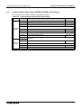
4.2
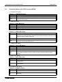
Allocation of Buffer Memories (BFMs) 4
Communication Status Flags <BFM #0, BFM #1> (Read Only)
The Communication Status flags are allocated as follows.
Table 4.2: Communication Status Flags (Read Only)
BFM No.
BFM #0
(000 H)
Bit No.
Description
Bit 0
Exchange Start End flag
Refer to 1)
Bit 1
Communication Trouble Detection flag
Refer to 2)
Bit 2
Communication Trouble Area Clear End flag
Refer to 3)
Bit 3
Not used
Bit 4
Global Control End flag
Refer to 4)
Bit 5
Global Control Error End flag
Refer to 5)
Bit 6 ~ 12
Bit 13
Bit 14 ~ 15
Bit 0 ~ 10
BFM #1
(001 H)
Name
Not used
Watchdog Timer Error flag
Not used
Bit 11
Communication READY flag
Bit 12
Not used
Bit 13
Module READY flag
Bit 14, 15
Refer to 6)
Refer to 7)
Refer to 8)
Not used
4-3
FX2N-64DP-M Profibus-DP Master Block
Allocation of Buffer Memories (BFMs) 4
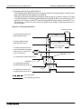
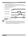
1) Exchange Start End flag <BFM #0 Bit 0>
This Exchange Start End flag can be used as an interlock for programmable controller write/
read output data and Input data to/from 64DP-M.
This flag is ON when the 64DP-M exchanges data with slave on the DP-network. This flag
is turned ON when the Exchange Start Request flag (BFM #2 Bit 0) is turned ON by a TO
instruction. This flag is turned OFF when Exchange Start Request flag is turned OFF by a
TO instruction, or when an error occurs that stops the exchange of data with the slave on
the DP-network.
Figure 4.1: Exchange Start End
Maximum 200 ms
Exchange Start Request flag
(BFM #2 (002 H) Bit 0)
ON
Exchange Start End flag
(BFM #0 (000 H) Bit 0)
The initial output data is write
to the Output Data Area (BFM
#1060 (424 H) ~ #2019 (7E3
H) by TO instruction.
ON
Exchanging data
to the slaves.
Write
BFM #28 = 1 → 0
The Initial Data Set (BFM #28 (01C H)
BFM #28 = 0 → 1
The Initial Output Data Set
flag (BFM #29 (01D H) Bit 14)
The Initalize Input Data Area
flag (BFM #29 (01D H) Bit 15)
ON
ON
:By user program
:Automatically by 64DP-M
4-4
FX2N-64DP-M Profibus-DP Master Block
Allocation of Buffer Memories (BFMs) 4
Note;
• Before the Exchange Start Request flag is turned ON the output data initial value must
be written to BFM #1060 (424 H) ~ #2019 (7E3 H).
For the Initial Data Set buffer memory, refer to section 4.7. For the Initial Output Data Set
flag and the Initialize Input Data Area flag, refer to section 4.8.
• There is a possibility that it is not possible to communicate with the slave, even if the
Exchange Start Request flag (BFM #2 Bit 0) is turned ON, when the slave power supply
is turned ON simultaneously with 64DP-M.
Therefore, please turn ON the Exchange Start Request flag after Communication
READY flag (BFM #1 Bit 11) is turned ON.
• It is not possible to stop the communication with slaves, even if the FX2N plc is in STOP.
Therefore, please turn OFF the Exchange Start Request flag, or each power supply of
the 64DP-M and FX2N plc, before the FX2N plc is in STOP.
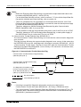
2) Communication Trouble Detection flag <BFM #0 Bit 1>
The Communication Trouble Detection flag can check that the communication diagnostic
error occurred.
This flag is turned ON when the communication diagnostic error occurs. At the same time
the RSP ERR LED turns ON, and Diagnostic Information is stored in BFM #2140 ~ #2179
<Communication Trouble Area>. This flag is turned OFF when the Communication Trouble
Detection Flag Reset flag (BFM #2 Bit 1) turns ON by a TO instruction. At the same time,
the RSP ERR LED is turned OFF.
Figure 4.2: Communication Trouble Detection Flag
Communication Trouble Detection Flag Reset flag
(BFM #2 (002 H) Bit 1)
Communication Trouble Detection flag
(BFM #0 (000 H) Bit 1)
The Diagnostic Information is read
form the Communication Trouble
Area <BFM #2140 (85C H) ~ #2179
(883 H)> by FROM instruction.
ON
ON
Read
:By user program
:Automatically by 64DP-M
Note;
• If this flag is turned ON, Diagnostic Information needs to be read from the
Communication Trouble Area area (BFM #2140 ~ #2179) by a FROM instruction.
• The Communication Trouble Detection Reset flag (BFM #2 Bit 1) is turned OFF by a TO
instruction after it has been confirmed that the Communication Trouble Detection flag
(BFM #0 Bit 1) has been turned OFF.
4-5
FX2N-64DP-M Profibus-DP Master Block
Allocation of Buffer Memories (BFMs) 4
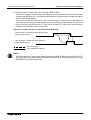
3) Communication Trouble Area Clear End flag <BFM #0 Bit 2>
The Communication Trouble Area Clear End flag can check that all of the Communication
Trouble Area (BFM #2140 ~ #2179) and the Expansion Communication Trouble Area (BFM
#2196 ~ #2210) are cleared.
This flag is turned ON when all of the Communication Trouble Area and Expansion
Communication Trouble Area are cleared by turning ON the Communication Trouble Area
Clear Request flag (BFM #2 Bit 2). This flag is turned OFF when the Communication
Trouble Area Clear Request is turned OFF.
Figure 4.3: Communication Trouble Area Clear End Flag
Communication Trouble Area Clear Request flag
(BFM #2 (002 H) Bit 2)
Communication Trouble Area Clear End flag
(BFM #0 (000 H) Bit 2)
ON
ON
:By user program
:Automatically by 64DP-M
Note;
The Communication Trouble Area Clear Request flag (BFM #2 Bit 2) is turned OFF by a TO
instruction after it has been confirmed that the Communication Trouble Area Clear End flag
(BFM #0 Bit 2) has been turned ON.
4-6
FX2N-64DP-M Profibus-DP Master Block
Allocation of Buffer Memories (BFMs) 4
4) Global Control End flag <BFM #0 Bit 4>
The Global Control End flag can check the finishing action of the global control service.
This flag is turned ON when the global control has finished, after the Global Control
Request flag (BFM #2 Bit 4) is turned ON by a TO instruction. This flag is turned OFF when
the Global Control Request flag is turned OFF.
For the Global Control, refer to chapter 5.
Figure 4.4: Global Control End
Exchange Start End flag
(BFM #0 (000 H) Bit 0)
ON
Global Control Request flag
(BFM #2 (002 H) Bit 4)
ON
Global Control End flag
(BFM #0 (000 H) Bit 4)
FROM/TO instruction for the Global Control.
ON
Write
Read
:By user program
:Automatically by 64DP-M
Note;
• The Global Control Request flag (BFM #2 Bit 4) is turned OFF by a TO instruction after it
has been confirmed that the Global Control End flag (BFM #0 Bit 4) has turned ON.
• The Global Control Request flag (BFM #2 Bit 4) cannot operate if the Exchange start
End flag (BFM #0 Bit 0) is OFF. In this case, the Global Control End flag (BFM #0 Bit 4)
and the Global Control Error End flag (BFM #0 Bit 5) will turn ON.
4-7
FX2N-64DP-M Profibus-DP Master Block
Allocation of Buffer Memories (BFMs) 4
5) Global Control Error End flag <BFM #0 Bit 5>
The Global Control Error End flag can check that the global control service does not
operate.
This flag is turned ON when the global control service does not operate. This flag is turned
OFF when the Global Control Request (BFM #2 Bit 4) turned ON → OFF.
For global control, refer to chapter 5.
Figure 4.5: Global Control Error End Flag
Global Control Request flag
(BFM #2 (002 H) Bit 4)
ON
Global Control Error End flag
(BFM #0 (000 H) Bit 5)
ON
:By user program
:Automatically by 64DP-M
Note;
• The Global Control Request flag (BFM #2 Bit 4) cannot operate if the Exchange start
End flag (BFM #0 Bit 0) is OFF. In this case, the Global Control End flag (BFM #0 Bit 4)
and the Global Control Error End flag (BFM #0 Bit 5) will turn ON.
• When the Global Control Error End flag is ON, the Input/Output data of the slave is not
held/deleted on the DP-network.
6) Watchdog Timer Error flag <BFM #0 Bit 13>
The Watchdog Timer Error flag can check that the Watchdog Timer Error occurs.
Table 4.3: Watchdog Timer Error Flag Status
Bit Status
Description
ON
Watchdog timer error occurs in the 64DP-M. In this case, 64DP-M cannot exchange
input data and output data to the slaves on the DP-network.
OFF
The 64DP-M is operating normally.
Caution;
If this flag is turned ON, the 64DP-M can restart by the following method. When it is not
possible to restart by these methods, please contact a service representative.
• Adjust the Master Reset (BFM #27) from “1” →”0”.
However, interval of 1 second or more is necessary when the Master Reset is changed
from “1” →”0”. For explanation of the Master Reset (BFM #27), refer to section 4.5.
• Turn the Restart Request flag (BFM #2 Bit 13) ON → OFF.
For the Restart Request flag, refer to subsection 4.3 6).
• Turn power supply of the 64DP-M and programmable controller OFF → ON.
4-8
FX2N-64DP-M Profibus-DP Master Block
Allocation of Buffer Memories (BFMs) 4
7) Communication READY flag <BFM #1 Bit 11>
The Communication READY flag can be used as an interlock when the Exchange Start
Request flag (BFM #2 Bit 0) turn ON by a TO instruction.
This flag is turned ON when the status of the 64DP-M can communicate to slaves on the
DP-network, after the 64DP-M has started up and the Module READY flag (BFM #1 Bit 13)
has turned ON. This flag is turned OFF when an error*1 occurs in the 64DP-M, and it is
impossible to communicate with slaves on the DP-network.
*1 When this error occurs, the FAULT LED will be ON. For checking point of the FAULT
LED, refer to chapter 10.
8) Module READY flag <BFM #1 Bit 13>
The Module READY flag can check that the 64DP-M has started up. If this flag is OFF, the
64DP-M cannot receive FORM/TO instructions form the programmable controller or
communicate to slaves on the DP-network.
This flag is turned ON when the 64DP-M is started up. Therefore, it is turned ON regardless
of the operation mode. This flag is OFF when the 64DP-M is powered down.
4-9
FX2N-64DP-M Profibus-DP Master Block
4.3
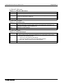
Allocation of Buffer Memories (BFMs) 4
Communication Control Flags <BFM #2> (Read / Write)
The Communication Control flags are allocated as follows.
Table 4.4: Communication Control Flags (Read / Write)
Bit No.
Name
Description
Bit 0
Exchange Start Request flag
Refer to 1) and
section 4.2 1)
Bit 1
Communication Trouble Detection Flag Reset flag
Refer to 2) and
section 4.2 2)
Bit 2
Communication Trouble Area Clear Request flag
Refer to 3) and
section 4.2 3)
Bit 3
Communication Trouble Area Type Selection flag
Refer to 4)
Bit 4
Global Control Request flag
Refer to 5),
section 4.2 4) and
chapter 6
Bit 5 ~ 12
Not used
Bit 13
Restart Request flag
Bit 14, 15
Not used
Refer to 6)
Caution;
Do not write “1 (ON)” to any bit that is “Not used” (Bit 5 ~ 12, 14, 15) from the programmable
controller. There is the possibility of corrupting the operation of the 64DP-M if writing “1” to
these bits.
1) Exchange Start Request flag <BFM #2 Bit 0>
The Exchange Start Request flag is used for exchanging data between the 64DP-M and the
slaves on the DP-network.
For further explanation, refer to section 4.2 1).
2) Communication Trouble Detection Flag Reset flag <BFM #2 Bit 1>
The Communication Trouble Detection Flag Reset flag is used to reset the Communication
Trouble Detection flag (BFM #0 Bit 1) and turn PSR ERR LED to OFF.
For further explanation, refer to section 4.2 2).
Note;
• Before the Exchange Start Request flag is turned ON the output data initial value must
be written to BFM #1060 (424 H) ~ #2019 (7E3 H).
For the Initial Data Set buffer memory, refer to section 4.7. For the Initial Output Data Set
flag and the Initialize Input Data Area flag, refer to section 4.8.
• There is a possibility that it is not possible to communicate with the slave, even if the
Exchange Start Request flag (BFM #2 Bit 0) is turned ON, when the slave power supply
is turned ON simultaneously with 64DP-M.
Therefore, please turn ON the Exchange Start Request flag after Communication
READY flag (BFM #1 Bit 11) is turned ON.
• It is not possible to stop the communication with slaves, even if the FX2N plc is in STOP.
Therefore, please turn OFF the Exchange Start Request flag, or each power supply of
the 64DP-M and FX2N plc, before the FX2N plc is in STOP.
4-10
FX2N-64DP-M Profibus-DP Master Block
Allocation of Buffer Memories (BFMs) 4
3) Communication Trouble Area Clear Request flag <BFM #2 Bit 2>
The Communication Trouble Area Clear Request flag is used to clear all of the
Communication Trouble Area (BFM #2140 ~ #2179) and the Expansion Communication
Trouble Area (BFM #2196 ~ #2210).
For further explanation, refer to section 4.2 3).
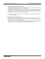
4) Communication Trouble Area Type Selection flag <BFM #2 Bit 3>
The Communication Trouble Area Type Selection flag is used to select Ring type or Fixed
type.
This flag is turned ON when selecting Fix type, or turned OFF when selecting Ring type.
This flag becomes valid when the Exchange Start End flag (BFM #0 Bit 0) change OFF →
ON, or the Communication Information Area Clear (Communication Trouble Area Clear) flag
(BFM #0 (000 H) Bit 2) changes from OFF → ON.
For Ring type and Fix type, refer to section 4.17.1
Figure 4.6: Communication Trouble Area Type Selection Flag
Communication Trouble Area Type Selection flag
(BFM #2 (002 H) Bit 3)
ON
Ring Type is chosen
This timing is for when the Exchange Start
End flag is turned OFF → ON ,or the
Communication Trouble Area Clear
Request flag is turned ON → OFF.
Fixed Type is chosen
Note;
The content of the selection does not change even if this flag is switched to the other type,
Fixed or Ring, after the selection has become valid.
Therefore, if changing the content of the selection, it is necessary that the Exchange Start
Request flag (BFM #2 Bit 0) is turned OFF → ON or the Communication Trouble Area Clear
Request flag (BFM #2 Bit 2) is turned ON → OFF.
5) Global Control Request flag <BFM #2 Bit 4>
The Global Control Request flag is used for operating global control.
For further explanation, refer to the subsection 4.2 4) and chapter 5.
6) Restart Request flag <BFM #2 Bit 13>
The Restart Request flag is used for restarting the 64DP-M when the main power fails,
either the FAULT LED is ON or Module READY flag is OFF.
When this flag is turned ON → OFF, the 64DP-M is restarted. This action is same as the
64DP-M turn power supply OFF → ON.
Caution;
The 64DP-M restarts when this flag is operated. Therefore, please make sure this bit is
turned OFF (default status) when it is not necessary to restart.
4-11
FX2N-64DP-M Profibus-DP Master Block
4.4
Allocation of Buffer Memories (BFMs) 4
Communication Stop Timer Setting <BFM #9> (Read / Write)
The communication stop timer is adjusted in 10 ms steps. Default value is 50 (50 × 10 ms =
500 ms). When this value is 0, the setting of the communication stop timer assumes it is
default value. The setting range is 0 and 10 ~ 6,000.
When FROM / TO instructions do not access any buffer memories, the communication timer
begins operating.
Note;
When restarting the communication between the 64DP-M and slaves on the DP-network,
do in the following process.
1) Write new values of communication stop timer to the Communication Stop Timer Setting
(BFM #9). The FROM / TO Error flag (BFM #29 Bit 9) is turned OFF.
2) Write initial or new output data to the Output Data Area (BFM #1060 ~ #2019), as the
contents of the Output Data Area is held when the FROM / TO Error occurs.
3) Turn OFF to ON the Exchange Start Request flag (BFM #2 Bit 0). The 64DP-M will start to
communicate to the slaves on the DP-network.
Caution;
If the communication timer reaches it is set time (BFM #9 × 10 ms), the 64DP-M
experiences a communication time out. At this time, The FROM / TO Error flag (BFM #29 Bit
9) is turned ON, and data will not be exchanged with slaves on the DP-network. The
Exchange Start Request flag (BFM #2 Bit 0) will turn OFF.
4-12
FX2N-64DP-M Profibus-DP Master Block
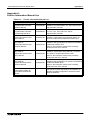
4.5
Allocation of Buffer Memories (BFMs) 4
Slave Data Consistency Mode <BFM #10 ~ #22>
BFM #10 is used for the selection of Slave Data Consistency Mode. This mode is used to
control the storage of data written in the output data area (BFM #1060 ~ #2019) in the send
buffer.
This mode is used to control output data is controlled. Output Data Send Request flags and
Sending End flags are used in each slave. For details on the Slave Data Consistency Mode
refer to subsection 4.5.1. For allocation of Output Data Send Request flags refer to subsection
4.5.2. For allocation of Output Data Sending End flags refer to subsection 4.5.3.
Table 4.5: Slave Data Consistency Mode <BFM #10> (Read / Write)
Value
Description
K0
Slave Data Consistency Mode disabled.
Other (≠ K0)
Slave Data Consistency Mode enabled.
Note:
When 64DP-M is exchanging data to the slaves, an error will result if the mode is changed.
When changing this mode, the Exchange Start End flag (BFM #0 bit 0) has to be OFF and
the Exchange Start Request flag (BFM #2 bit 0) is turned OFF.
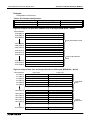
Figure 4.7: Input/Output Data Areas and Receive/Send Buffers
64DP-M
DP-Slave
Input Data Area
(BFM #100 ~ #1059)
Receive
Buffer
Output Data Area
(BFM #1060 ~ #2019)
Send
Buffer
This process can be controlled by the user
program in Slave Data Consistency Mode.
This process can be controlled by the user program
with the Global Control Function.
Note:
In the update of the data between 64DP-M and the slave, the data consistency can usually
be kept to only the units of a single word. Therefore, 64DP-M has Slave Data Consistency
Mode and Global Control Function. Refer to the table below for consistency of sending/
receiving data and the relation of each function.
Table 4.6: Consistency of Exchanged Data
Using Function
Using Slave Data Consistency Mode
Using Global Control
Function
Sending Data
(To Slave)
Receiving Data
(From Slave)
Single word data
ü
ü
Multiple word data
Single word data
ü
Slave data
consistency
Slave data
consistency
ü
Single word data
Slave data
consistency
4-13
FX2N-64DP-M Profibus-DP Master Block
4.5.1
Allocation of Buffer Memories (BFMs) 4
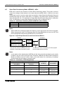
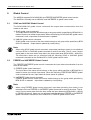
Slave Data Consistency Mode Process
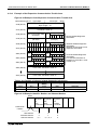
The Slave Data Consistency Mode process is shown in Figure 4.8. When sending output data
to the slave, the Output Data Send Request flag is turned ON. When output data has been
stored in the send buffer, the Output Data Sending End flag is turned ON by 64DP-M. In this
case, the output data of the 64DP-M will be sent to the slave. If an error occurs, the Output
Data Send Error flag is turned ON.
For allocation of the Output Data Send Request flags, refer to Table 4.7. For allocation of the
Output Data Sending End flags, refer to Table 4.8. For allocation of the Output Data Send Error
flags, refer to Table 4.9.
Figure 4.8: Slave Data Consistency Mode Process
Writes the data to the output area by
TO instruction.
Do not write to output data area
of the slave at this time.
Write
Output Data Send Request flag
Output Data Sending End flag
ON
ON
:By user program
:Automatically by 64DP-M
Note
Output data is not stored in the send buffer unless the Output Data Request flag is ON. The
data is written only to the Output Data area (BFM #1060 ~ #2019). See Figure 4.7.
4-14
FX2N-64DP-M Profibus-DP Master Block
4.5.2
Allocation of Buffer Memories (BFMs) 4
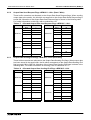
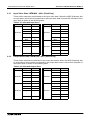
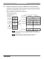
Output Data Send Request Flags <BFM #11 ~ #14> (Read / Write)
These buffer memories are allocated to the Output Data Send Request flags. When sending
output data to the station, the bit which corresponds to the Output Data Send Request flag is
turned ON. Allocation of the Output Data Send Request flags is shown in the following table.
For further information on this flag, refer to subsection 4.5.1
Table 4.7: Allocated Output Data Send Request Flags <BFM #11 ~ #14>
BFM No.
BFM #11
Bit No.
Station No.
Bit 0
BFM No.
Bit No.
Station No.
1
Bit 0
33
Bit 1
2
Bit 1
34
Bit 2
3
Bit 2
35
BFM #13
:
:
:
:
Bit 15
16
Bit 15
48
Bit 0
17
Bit 0
49
Bit 1
20
Bit 1
50
Bit 2
21
Bit 2
51
:
:
:
:
:
:
:
:
Bit 11
60
Bit 15
32
BFM #12
4.5.3
BFM #14
Bit 12 ~ 15 Not used
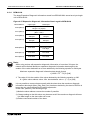
Output Data Sending End Flags <BFM #15 ~ #18> (Read Only)
These buffer memories are allocated to the Output Data Sending End flags. When output data
has been stored in the send buffer, the bit which corresponds to the Output Data Sending End
flag is turned ON by 64DP-M. Allocation of the Output Data Sending End flags is shown in the
following table. For further information on this flag, refer to subsection 4.5.1.
Table 4.8: Allocated Output Data Sending End Flags <BFM #15 ~ #18>
BFM No.
BFM #15
Bit No.
Station No.
Bit 0
BFM No.
Bit No.
Station No.
1
Bit 0
33
Bit 1
2
Bit 1
34
Bit 2
3
Bit 2
35
BFM #17
:
:
:
:
Bit 15
16
Bit 15
48
Bit 0
17
Bit 0
49
Bit 1
20
Bit 1
50
Bit 2
21
Bit 2
51
:
:
:
:
:
:
:
:
Bit 11
60
Bit 15
32
BFM #16
BFM #18
Bit 12 ~ 15 Not used
4-15
FX2N-64DP-M Profibus-DP Master Block
4.5.4
Allocation of Buffer Memories (BFMs) 4
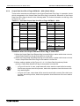
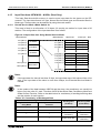
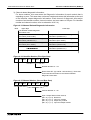
Output Data Send Error Flags <BFM #19 ~ #22> (Read / Write)
These buffer memories are allocated to the Output Data Send Error flags. In operation, the bit
which corresponds to the Output Data Send Error flag is turned ON. Allocation of the Output
Data Send Error flags is shown in the following table. For further information on this flag, refer
to Figure 4.9 ~ 4.11
Table 4.9: Allocated Output Data Send Error Flags <BFM #19 ~ #22>
BFM No.
BFM #11
Bit No.
Station No.
Bit 0
BFM No.
Bit No.
Station No.
1
Bit 0
33
Bit 1
2
Bit 1
34
Bit 2
3
Bit 2
35
BFM #13
:
:
:
:
Bit 15
16
Bit 15
48
Bit 0
17
Bit 0
49
Bit 1
20
Bit 1
50
Bit 2
21
Bit 2
51
:
:
:
:
:
:
:
:
Bit 11
60
Bit 15
32
BFM #12
BFM #14
Bit 12 ~ 15 Not used
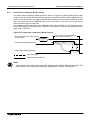
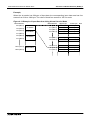
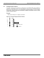
Situations when the Output Data Send Error flag is turned ON
1) When the Output Data Send Request flag is turned ON by a station which does not exist,
Output Data Send Error flag for that station is turned ON.
2) When the Output Data Send Request flag is turned ON by a station which does not have
output, Output Data Send Error flag for that station is turned ON.
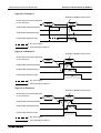
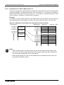
3) When making mistake as like Figure 4.9 ~ 4.11 in Slave Data Consistency Mode
process, Output Data Send Error flag for that station is turned ON.
• In Figure 4.9 and 4.11 case, output data will not be stored to send buffer incorrectly.
Check user program about this process, before this operation should be done to the
error station again.
• In Figure 4.10 case, output data will be stored to send buffer correctly. But check user
program about this process, before this operation should be done to the error station
next time.
4-16
FX2N-64DP-M Profibus-DP Master Block
Allocation of Buffer Memories (BFMs) 4
Figure 4.9: Example 1
Rewrites to BFMs for same slave
Writes data to the output data area
by TO instruction.
Write
Write
ON
Output Data Send Request flag
ON
Output Data Sending End flag
Output Data Send Error flag
ON
ON
:By user program
:Automatically by 64DP-M
Figure 4.10:Example 2
Rewrites to BFMs for same slave
Writes data to the output data area
by TO instruction.
Write
Write
ON
Output Data Send Request flag
Output Data Sending End flag
ON
Output Data Send Error flag
ON
:By user program
:Automatically by 64DP-M
Figure 4.11:Example 3
Rewrites to BFMs for same slave
Writes data to the output data area
by TO instruction.
Write
Output Data Send Request flag
Write
ON
Output Data Sending End flag
ON
Output Data Send Error flag
ON
:By user program
:Automatically by 64DP-M
4-17
FX2N-64DP-M Profibus-DP Master Block
4.6
Allocation of Buffer Memories (BFMs) 4
Master Reset <BFM #27> (Read / Write)
The Master Reset buffer memory is used when changing to the test mode or the parameter set
mode. When the value of this buffer memory is “K1”, the 64DP-M can be changed to the test
mode or parameter set mode. When the value of this buffer memory is changed to “K0”, the
64DP-M will restart.
However, interval of 1 second or more is necessary when the Master Reset is changed to “K0”.
When finished in the test mode or parameter mode, reset the power supply for PLC and 64DPM.
Table 4.10: Master Reset
Value
Description
K1 → K0
64DP-M will restart. Do not access 64DP-M for 1 second by FROM/TO
instruction at when 64DP-M is restarting.
K0 → K1
64DP-M stop to access Profibus-DP system.
An interval of 1 second or more is necessary when the Master Reset is
changed to “K0”.
Caution;
• The 64DP-M restarts when the value of this buffer memory changes to “K0”. Therefore,
please do not access this buffer memory when it is not necessary to restart or change
the test mode and the parameter set mode.
4.7
Initial Data Set <BFM #28> (Read / Write)
The Initial Data Set buffer memory is used to check that the initial data for output to slaves on
the DP-network has finished to write to the Output Data Area buffer memory (BFM #1060 ~
BFM #2019).
A value of “1” is written to this BFM when the initial contents of the Output Data Area is for all
slaves, after these status flags (BFM #29 Bit 14, 15) are turned ON. When these flags are ON,
a value of “0” is written to this BFM and the Exchange Start Request flag (BFM #2 Bit 0) is
turned ON. At this time, the Exchange Status Request flags are turned OFF.
For status flags (BFM #29 Bit 14, 15), refer to section 4.8.
Caution;
This process is necessary for the 64DP-M to communicate correctly with the slaves on the
DP-network.
If the Exchange Start Request flag is turned ON before the initial data is prepared in the
64DP-M, it will communicate incorrectly with slaves on the DP-network.
4-18
FX2N-64DP-M Profibus-DP Master Block
4.8
Allocation of Buffer Memories (BFMs) 4
Master Status <BFM #29> (Read Only)
The Master Status buffer memory is allocated as shown on the following table.
Table 4.11: Master Status <BFM #29 (01D H)>
Bit No.
Name
Description
ON when the value of the Master Reset buffer memory
(BFM #27) is “1”.
Bit 0
Master Reset Status flag
Bit 1 ~ 7
Not used
Bit 8
BFM Access Error flag
ON when accessing the buffer memory of “Not used”.
Bit 9
Communication Stop Timer
Timed Up flag
ON when the Communication Stop Timer is timed up.
Bit 10 ~ 11 Not used
4.9
Bit 12
ON when writing to the Communication Control flags
Writing Communication Control buffer memory (BFM #2) by TO instruction. This flag uses
Status flag
an interlock for exclusive assessing to the
Communication Control flags buffer memory.
Bit 13
Not used
Bit 14
Initial Output Data Set flag
ON when the 64DP-M finishes to set initial data for output
of the slaves. OFF when writing “0” to the Initial Data Set
buffer memory (BFM #28).
Bit 15
Initialize Input Data Area flag
ON when the 64DP-M finishes to initialize data for input
of the slaves. OFF when writing “0” to the Initial Data Set
buffer memory (BFM #28).
Module ID code <BFM #30> (Read Only)
The identification code for a 64DP-M is available using a FROM instruction. The identification
code for the 64DP-M is K7060. By reading this identification code, the user may create built-in
checking routines to check whether the physical position of 64DP-M matches the software.
4.10
Number of Used Input Byte <BFM #37> (Read Only)
This buffer memory is used to check the 64DP-M for the number of bytes used in the input data
area. This value may be more than the value of the configuration software. As the occupied
number of bytes is included in this value.
4.11
Number of Allocated Slave <BFM #38> (Read Only)
This buffer memory is used to check the number of slaves connected to the 64DP-M. This
value is same as the number of slaves in the configuration software.
4.12
Operation Service Mode <BFM #39> (Read Only)
This buffer memory is used to check the operation service mode of the 64DO-M.
Table 4.12: Operation Service Mode
Value (Hex)
Description
0
64DP-M is in normal service mode.
E
64DP-M is in extended service mode.
Other value
Configuration error will be occurred in 64DP-M.
4-19
FX2N-64DP-M Profibus-DP Master Block
4.13
Allocation of Buffer Memories (BFMs) 4
Input Slave State <BFM #40 ~ #43> (Read Only)
These buffer memories are allocated to the input slave state. When the 64DP-M already has
an input slave, the bit which corresponds to the input slave state is turned ON. Allocation of the
input slave is shown in the following table.
Table 4.13: Allocated Input Slave
BFM No.
BFM #40
Bit No.
Slave No.
Bit 0
BFM No.
Bit No.
Slave No.
1
Bit 0
33
Bit 1
2
Bit 1
34
Bit 2
3
Bit 2
35
BFM #42
:
:
:
:
Bit 15
16
Bit 15
48
Bit 0
17
Bit 0
49
Bit 1
18
Bit 1
50
Bit 2
19
Bit 2
51
:
:
:
:
:
:
:
:
Bit 11
60
Bit 15
32
BFM #41
4.14
BFM #43
Bit 12 ~ 15 Not used
Output Slave State <BFM #44 ~ #47> (Read Only)
These buffer memories are allocated to the output slave state. When the 64DP-M already has
an output slave, the bit which corresponds to the output slave state is turned ON. Allocation of
the output slave is shown in the following table.
Table 4.14: Allocated Output Slave
BFM No.
BFM #44
Bit No.
Slave No.
Bit 0
BFM No.
Bit No.
Slave No.
1
Bit 0
33
Bit 1
2
Bit 1
34
Bit 2
3
Bit 2
35
BFM #46
:
:
:
:
Bit 15
16
Bit 15
48
Bit 0
17
Bit 0
49
Bit 1
18
Bit 1
50
Bit 2
19
Bit 2
51
:
:
:
:
:
:
:
:
Bit 11
60
Bit 15
32
BFM #45
BFM #47
Bit 12 ~ 15 Not used
4-20
FX2N-64DP-M Profibus-DP Master Block
4.15
Allocation of Buffer Memories (BFMs) 4
Input Data Area <BFM #100 ~ #1059> (Read Only)
This Input Data Area buffer memory is used to store input data for the slaves on the DPnetwork. The input data format is 2 type, Normal Service Mode type and Extended Service
Mode type. These modes can be selected by using the mode switch.
4.15.1
Normal Service Mode <Mode Switch: 0>
This area is fixed to an allocation of 32 bytes (16 words) per station for input data of 60
stations. The configuration of the input data area is as follows.
Figure 4.12:Input Data Area Using Normal Service Mode
BFM Address
100 (064 H)
Upper byte
2nd byte
4th byte
7th byte
9th byte
Lower byte
1st byte
3th byte
5th byte
8th byte
115 (073 H)
116 (074 H)
117 (075 H)
118 (076 H)
119 (077 H)
32th byte
2nd byte
4th byte
7th byte
9th byte
31th byte
1st byte
3th byte
5th byte
8th byte
131 (083 H)
32th byte
31th byte
BFM Address
100 (064 H)
101 (065 H)
102 (066 H)
103 (067 H)
1st station
115 (073 H)
116 (074 H)
2nd station
Bit 0
131 (083 H)
132 (084 H)
3rd station
147 (093 H)
1044 (414 H)
60th station
1059 (423 H)
Note;
If the input data of a slave is less than 32 byte, the input data area of this slave will be a free
area. If the input data of the slave is more than 32byte, the Extended Service Mode is
needed.
Note:
In the update of the data between 64DP-M and the slave, the consistency can usually be
kept to only the units of 1 word. Therefore, 64DP-M has Slave Data Consistency Mode and
Global Control Function. Refer to the table below for consistency of sending/receiving data
and the relation of each function.
Table 4.15: Consistency of Exchanged Data
Using Function
Using Slave Data Consistency Mode
Using Global Control
Function
Sending Data
(To Slave)
Receiving Data
(From Slave)
Single word data
ü
ü
Multiple word data
Single word data
ü
Slave data
consistency
Slave data
consistency
ü
Single word data
Slave data
consistency
4-21
FX2N-64DP-M Profibus-DP Master Block
Allocation of Buffer Memories (BFMs) 4
Example;
When the 1st station has 20 bytes of input data, the corresponding input data area has free
sectors from 21th to 32th byte. The value of these free sectors is “00” hex code.
Figure 4.13:Example of Input Data Area Using Normal Service Mode
BFM Address
100 (064 H)
1st station
115 (073 H)
116 (074 H)
2nd station
Upper byte
2nd byte
4th byte
7th byte
9th byte
Lower byte
1st byte
3th byte
5th byte
8th byte
109 (06D H)
110 (06E H)
20th byte
Not used
19th byte
Not used
115 (073 H)
116 (074 H)
117 (075 H)
Not used
2nd byte
4th byte
Not used
1st byte
3th byte
BFM Address
100 (064 H)
101 (065 H)
102 (066 H)
103 (067 H)
131 (083 H)
132 (084 H)
3rd station
147 (093 H)
1044 (414 H)
60th station
1059 (423 H)
4-22
Bit 0
FX2N-64DP-M Profibus-DP Master Block
4.15.2
Allocation of Buffer Memories (BFMs) 4
Extended Service Mode <Mode Switch: E>
This area is assigned in variable length according to the parameter file set in the configuration
software (ProfiMap). The data length can be set in the range of 0 ~ 244 bytes. The number of
stations that can be set will vary in the range of 1 ~ 60. However, this Input Data Area is 1920
bytes (32 bytes × 60 stations = 1920 bytes) for all slaves.
Example;
An example is shown below where the input data length of the 1st station is 23 bytes and the
input data length of the 2nd station is 7 bytes. The value of this free area is “00” hex code.
Figure 4.14:Example of Input Data Area Using Extended Service Mode
BFM Address
100 (064 H)
1st station
111 (06F H)
112 (070 H)
2nd station
BFM Address
100 (064 H)
101 (065 H)
102 (066 H)
103 (067 H)
Upper byte
2nd byte
4th byte
6th byte
8th byte
Lower byte
1st byte
3th byte
5th byte
7th byte
Not used
2nd byte
4th byte
6th byte
Not used
2nd byte
23th byte
1st byte
3rd byte
5th byte
7th byte
1st byte
Bit 0
115 (073 H)
116 (074 H)
3rd station
111 (06F H)
112 (070 H)
113 (071 H)
114 (072 H)
115 (073 H)
116 (074 H)
Note;
• When the data length is an odd number of bytes, the last upper byte becomes a free
area as the 1st byte of station data needs to be assigned as a lower byte, and data for
the next station is assigned from the next address.
• When the data length is 0 byte, the input data area for this station will be not be in the
Input Data Area buffer memory.
4-23
FX2N-64DP-M Profibus-DP Master Block
4.16
Allocation of Buffer Memories (BFMs) 4
Output Data Area <BFM #1060 ~ #2019> (Read / Write)
This Output Data Area buffer memory is used to stored output data for the slaves on the DPnetwork. The output data format is 2 type, Normal Service Mode type and Extended Service
Mode type. These mode can be chosen by mode switch.
Caution;
Even if the programmable controller is in “STOP”, output data is maintained. Therefore,
1) Appropriate output data must be sent, before the programmable controller is “STOP”.
2) The entire system must stop before the programmable controller enters in “STOP”.
Note;
Appropriate initial data should be stored in the send buffer (Output Data Area <BFM #1060
~ #2019>) before it begins to communicate.
4.16.1
Normal Service Mode <Mode Switch: 0>
This area is fixed to an allocation of 32 bytes (16 words) per station for input data of 60
stations. The configuration of output data area is as follows.
Figure 4.15:Output Data Area Using Normal Service Mode
BFM Address
1060 (424 H)
1st station
1075 (433 H)
1076 (434 H)
2nd station
BFM Address
1060 (424 H)
1061 (425 H)
1062 (426 H)
1063 (427 H)
Upper byte
2nd byte
4th byte
7th byte
9th byte
Lower byte
1st byte
3th byte
5th byte
8th byte
1075 (433 H)
1076 (434 H)
1077 (435 H)
1078 (436 H)
1079 (437 H)
32th byte
2nd byte
4th byte
7th byte
9th byte
31th byte
1st byte
3th byte
5th byte
8th byte
1091 (443 H)
32th byte
31th byte
Bit 0
1091 (443 H)
1092 (444 H)
3rd station
1107 (453 H)
2004 (7D4 H)
60th station
2019 (7E3 H)
Note;
If the output data of the slave is less than 32 byte, the output data area of this slave will have
a free area. If output data of the slave is more than 32byte, the Extended Service Mode, will
need to be used.
4-24
FX2N-64DP-M Profibus-DP Master Block
Allocation of Buffer Memories (BFMs) 4
Note:
In the update of the data between 64DP-M and the slave, the consistency can usually be
kept to only the units of 1 word. Therefore, 64DP-M has Slave Data Consistency Mode and
Global Control Function. Refer to the table below for consistency of sending/receiving data
and the relation of each function.
Table 4.16: Consistency of Exchanged Data
Using Function
Using Slave Data Consistency Mode
Using Global Control
Function
Sending Data
(To Slave)
Receiving Data
(From Slave)
Single word data
ü
ü
Multiple word data
Single word data
ü
Slave data
consistency
Slave data
consistency
ü
Single word data
Slave data
consistency
Example;
When the 1st station has 20 bytes for output data, the output data area of 1st station has free
area of 21th ~ 32th byte. The value of this free area is “00” hex code.
Figure 4.16:Example of Output Data Area Using Normal Service Mode
BFM Address
1060 (424 H)
1st station
1075 (433 H)
1076 (434 H)
2nd station
BFM Address
1060 (424 H)
1061 (425 H)
1062 (426 H)
1063 (427 H)
Upper byte
2nd byte
4th byte
7th byte
9th byte
Lower byte
1st byte
3th byte
5th byte
8th byte
1069 (42C H)
1070 (42D H)
20th byte
Not used
19th byte
Not used
1075 (433 H)
1076 (434 H)
1077 (435 H)
Not used
2nd byte
4th byte
Not used
1st byte
3th byte
1091 (443 H)
1092 (444 H)
3rd station
1107 (453 H)
2004 (7D4 H)
60th station
2019 (7E3 H)
4-25
Bit 0
FX2N-64DP-M Profibus-DP Master Block
4.16.2
Allocation of Buffer Memories (BFMs) 4
Extended Service Mode <Mode Switch: E>
This area is assigned in variable length according to the parameter file set in the configuration
software (ProfiMap). The data length can be set in the range of 0 ~ 244 bytes. The number of
stations that can be set will vary in the range of 1 ~ 60. However, this Output Data Area is 1920
bytes (32 bytes × 60 stations = 1920 bytes) for all slaves. The value of this free area is “00” hex
code.
Example;
An example is shown below where the output data length of the 1st station is 23 bytes and the
output data length of the 2nd station is 7 bytes.
Figure 4.17:Example of Output Data Area Using Extended Service Mode
BFM Address
1060 (424 H)
1st station
1071 (42F H)
1072 (430 H)
2nd station
BFM Address
1060 (424 H)
1061 (425 H)
1062 (426 H)
1063 (427 H)
Upper byte
2nd byte
4th byte
6th byte
8th byte
Lower byte
1st byte
3th byte
5th byte
7th byte
1071 (42F H)
1072 (430 H)
1073 (431 H)
1074 (432 H)
1075 (433 H)
1076 (434 H)
Not used
2nd byte
4th byte
6th byte
Not used
2nd byte
23th byte
1st byte
3rd byte
5th byte
7th byte
1st byte
Bit 0
1075 (433 H)
1076 (434 H)
3rd station
Note;
• When the data length is an odd number of bytes, the last upper byte becomes a free
area as the 1st byte of the station data needs to be assigned as a lower byte, and data
for the next station is assigned from the next address.
• When the data length is 0 byte, the output data area for this station will not be in the
Output Data Area buffer memory.
4-26
FX2N-64DP-M Profibus-DP Master Block
4.17
Allocation of Buffer Memories (BFMs) 4
Address Information Area <BFM #2020 ~ #2139> (Read Only)
This Address Information Area buffer memory can check that the slave address number, the
input data bytes length and the output data length of all slaves is assigned by the configuration
software (ProfiMap). The Address Information Area assign as follows.
The station number is not the slave address number. Therefore, the setting range of slave
address number is 1 ~ 126. Slave addresses do not need to be sequential numbers.
Figure 4.18:Address Information Area
BFM Address Bit 15
Upper byte
Lower byte
Bit 0
2020 (7E4 H)
Slave address of 1st station
2021 (7E5 H) 1st station output byte length
1st station input byte length
2022 (7E6 H)
Slave address of 2nd station
2023 (7E7 H) 2nd station output byte length 2nd station input byte length
2138 (85A H)
2139 (85B H)
Slave address of 60th station
60th station output byte length 60th station input byte length
Note;
Any station address that is not assigned by the configuration software (ProfiMap) is
assigned “FFFF” hex code, the input or output byte length is “FF” hex code.
Example;
When using the Extended Service Mode, the relation among the Address Information Area
(BFM #2020 ~ #2139), Input Data Area (BFM #100 ~ #1059) and Output Data Area (BFM
#1060 ~ #2019) is as follows.
Figure 4.19:Example of Address Information Area
BFM Address Bit 15
Upper byte
Lower byte
Bit 0
2020 (7E4 H)
Slave address of 1st station = 5 H
2021 (7E5 H)
1st station output byte length = 0
1st station input byte length =3
2022 (7E6 H)
Slave address of 2nd station = 10 H
2023 (7E7 H)
2nd station output byte length = 5 H
2nd station input byte length = 7 H
2024 (7E8 H)
Slave address of 3rd station = FFFF H
2025 (7E9 H) 3rd station output byte length = FF H
3rd station input byte length =FF H
2138 (85A H)
2139 (85B H)
Slave address of 60th station = FFFF H
60th station output byte length = FF H 60th station input byte length = FF H
4-27
FX2N-64DP-M Profibus-DP Master Block
Allocation of Buffer Memories (BFMs) 4
Figure 4.20:Input Data Area and Output Data Area
BFM Address
100 (064 H)
1st station
101 (065 H)
102 (066 H)
2nd station
105 (069 H)
106 (06A H)
1059 (423 H)
This slave does
not have
output.
1060 (424 H)
This area is
not used in
this system
configuration
1st station
2nd station
1062 (426 H)
1063 (427 H)
2019 (7E3 H)
This area is
not used in
this system
configuration
BFM Address
100 (064 H)
101 (065 H)
102 (066 H)
103 (067 H)
104 (068 H)
105 (069 H)
106 (06A H)
107 (06B H)
Upper byte
2nd byte
Not used
2nd byte
4th byte
6th byte
Not used
Not used
Not used
Lower byte
1st byte
3th byte
1st byte
3rd byte
5th byte
7th byte
Not used
Not used
1059 (423 H)
1060 (424 H)
1061 (425 H)
1062 (426 H)
1063 (427 H)
1064 (428 H)
Not used
2nd byte
4th byte
Not used
Not used
Not used
Not used
1st byte
3th byte
5th byte
Not used
Not used
2019 (7E3 H)
Not used
Not used
Figure 4.21:System configuration of Example
FX2N-32MR
FX2N-64DP-M
Slave
Slave address No.:
Input data length:
Output data length:
Slave
10
7 bytes
5 bytes
Slave address No.:
Input data length:
Output data length:
5
3 bytes
0 bytes
4-28
Bit 0
FX2N-64DP-M Profibus-DP Master Block
4.18
Allocation of Buffer Memories (BFMs) 4
Communication Trouble Area <BFM #2140 ~ #2179> (Read Only)
This Communication trouble area can check the Diagnostic Information of a slave when a
communication error occurs on the DP-network (in this case, the Communication Trouble
Detection flag (BFM #0 Bit 1) will be ON.). When some kind of error occurs on the DP-network,
Diagnostic Information is stored in this area. It contains the Error Code, Detailed Data Length
and Detailed Data. The method storing is 2 type, Ring Type and Fixed Type. These 2 types
can be chosen by the Communication trouble Area Type Selection flag (BFM #2 Bit 3) turned
ON or OFF. When this flag is turned ON, Fixed Type is chosen. When this flag is turned OFF,
Ring Type is chosen.
Regardless of the storage method (Fixed Type or Ring Type), up to 8 sets of Diagnostic
Information can be stored in this area. The area can be cleared by turning ON the
Communication Trouble Area Clear Request flag (BFM #2 Bit 2). This area is assigned as
follows.
For the Communication Trouble Detection flag, refer to section 4.2. For the Communication
Trouble Area Clear Request flag, refer to section 4.3.
Figure 4.22:Communication Trouble Area configuration
BFM Address
2140 (85C H)
2144 (860 H)
2145 (861 H)
2149 (865 H)
2150 (866 H)
2154 (86A H)
2175 (87F H)
2179 (883 H)
Information
area 1
Information
area 2
BFM Address
2140 (85C H)
2141 (85D H)
2142 (85E H)
2143 (85F H)
2144 (860 H)
Error code (Refer to subsection 4.17.2.)
Detailed data length (0 ~ 3 H)
Detail data 1
Detail data 2
Detail data 3
Information
area 3
Information
area 8
4-29
FX2N-64DP-M Profibus-DP Master Block
4.18.1
Allocation of Buffer Memories (BFMs) 4
Fixed Type and Ring Type methods
With Fixed type, when 8 pieces of Diagnostic Information are stored, areas 2 to 8 are fixed, so
when the next new diagnostic communication occurs only header area 1 is updated. Refer to
Figure 4.23.
Ring type is stored in order from the header, with the header always being the last Diagnostic
Information. Refer to Figure 4.24
Figure 4.23:The Fixed Type
New Diagnostic Information
Information
area 1
1st Information
2nd Information
8th Information
9th Information
1st
Information
2nd
Information
8th
Information
9th
Information*1
1st
Information
7th
Information
7th
Information
This area is
not the
Diagnostic
Information
now.
2nd
Information
2nd
Information
1st
Information
1st
Information
Information
area 2
Information
area 3
This area is
not the
Diagnostic
Information
now.
Information
area 8
*1 This Diagnostic Information is discarded.
Figure 4.24:The Ring Type
New Diagnostic Information
Information
area 1
1st Information
2nd Information
8th Information
9th Information
1st
Information
2nd
Information
8th
Information
9th
Information
1st
Information
7th
Information
8th
Information
This area is
not the
Diagnostic
Information
now.
2nd
Information
3rd
Information
1st
Information
2nd
Information*1
Information
area 2
Information
area 3
Information
area 8
This area is
not the
Diagnostic
Information
now.
*1 This Diagnostic Information is discarded.
4-30
FX2N-64DP-M Profibus-DP Master Block
4.18.2
Allocation of Buffer Memories (BFMs) 4
Error codes
Error codes are shown in the following table.
Table 4.17: Error Codes in the Diagnostic Information
Error
code
Data
length
0200 H
3
1121 H
1
1300 H
2
3000 H
1
Detailed Data
Data 1
Data 2
Data 3
Refer to 1)
03 H
-
Refer to 3)
Ignored
-
Communication Status
Continues communication
-
Further Information
Refer to 1)
Refer to 2)
Stops communication after
the error occurs.
-
Refer to 3)
Refer to 4)
1) Error code: 0200 H
When this error occurs, configuration of the Diagnostic Information assigns following figure
4.25.
In addition, the Expansion Diagnostic Information is stored in the Expansion communication
Trouble Area <BFM #2196 ~ #2210> for only the latest the Diagnostic Information of the
error code = 0200 H.
Figure 4.25:Configuration of the Diagnostic Information Occurring 0200 H Error Code
Error Code = 0200 H
Detailed data length = 3 H
Detail Data 1 Master Address *1 (hex code) Slave Address *2 (hex code)
Detail Data 2
Diagnostic Status (Refer to Table 4.14.) *3 (hex code)
Detail Data 3
Slave ID *4 (hex code)
*1 The address of the master that controls the slave in which this Diagnostic Information
occurred is stored.
However, FF H is stored when the Diagnostic Information shows that communication to
the slave is failed.
*2 The address of the slave in which this Diagnostic Information occurred is stored.
*3 This diagnostic status is assigned as follows table 4.16.
*4 The NPO ID code of the slave is stored.
However, FF H is stored when the Diagnostic Information shows that communication to
the slave is failed.
4-31
FX2N-64DP-M Profibus-DP Master Block
Allocation of Buffer Memories (BFMs) 4
Table 4.18:Diagnostic Bit Status
Bit
No.
Name
Description and Check points
Setting
Station
slave
slave
Bit 0
Parameter
allocation request
Master parameter allocation request from slave.
This diagnostic information will always occur at exchange start, so it
can be ignored.
If this diagnostic information occurs during exchange, check the
slave status and communication line.
Bit 1
Slave status error
Master diagnostic data read request from slave.
If this bit is ON, check the slave status.
Bit 2
Not used (This bit is OFF.)
Bit 3
WDT monitoring
Watchdog monitoring is being conducted in the slave.
(normal operation)
slave
Bit 4
FREEZE mode
This slave in FREEZE mode. (normal operation)
slave
Bit 5
SYNC mode
This slave in SYNC mode. (normal operation)
slave
Bit 6
Not used (This bit is OFF.)
Bit 7
The cyclic
communication
stop
The cyclic communication for this module was separated by the
parameter setting.
This diagnostic information will always occur at exchange start, so it
can be ignored.
If this bit is ON, check the parameter on the DP-network was
changed by class 2 master.
Bit 8
No comms with
slave
Master can not communicate with slave.
Check the slave status and communication circuit. And check the
parameter.
Master
Bit 9
Slave not ready
The slave is not ready to exchange.
This diagnostic status will always occur at exchange start, check
the slave status and communication circuit.
slave
Bit 10
Parameter
mis-match
The parameter received for byte length of Input/Output from the
master does not match that of the slave.
Check the slave parameter.
slave
Expansion
Diagnostic
Bit 11
Information
received
Expansion Diagnostic Information received.
Master
Master
Bit 12
Not support
function
The function requested by the master is not supported in the slave.
Bit 13
Incorrect slave
data
Data from the slave is incorrect.
Bit 14
Incorrect
parameter
The parameter transmitted to this slave by the master is incorrect.
Bit 15
Multiple master
comms
This slave is controlled by another master.
slave
Master
slave
Master
4-32
FX2N-64DP-M Profibus-DP Master Block
Allocation of Buffer Memories (BFMs) 4
2) Error code: 1121 H
This error means that the slave address specified in the parameter is the same as that of
the master.
This error occurs immediately after the power supply is turned ON or the 64DP-M is reset.
Even though this error is occurring, if the Exchange Start Request (BFM #2 Bit 0) is ON
then error code 3000h will occur, the FAULT LED will turn ON and operation will stop.
Check Point
Check the slave address and master address. If these are same address, set these address
correctly.
3) Error code: 1300 H
This error means that no active slaves are set in the parameter. When this error occurs the
detailed data is set number of slaves set in the parameter to the detailed data 1.
This error occurs immediately after the power supply is turned ON or the 64DP-M is reset.
Even though this error is occurring, if the Exchange Start Request(BFM2:b0) is on then
error 3000h will occur, the FAULT LED will turn ON, and operation will stop.
Check Points
a) Set 1 or more active slave in the parameter.
b) When the FAULT LED is turned on, reset by turning OFF → ON → OFF the BFM #0 Bit
13 for (a) above.
4) Error code: 1302 H
This error means that the capacity of the parameter area is insufficient.
This error occurs immediately after the power supply is turned ON or the 64DP-M is reset.
When this error has occurred, the FAULT LED will turn ON, and operation will stop.
Check Points
Check capacity of the parameter area and expansion diagnostic information data length.
Please, decrease the number of slaves or change slave's type.
For expansion diagnostic information data length, refer to the either Note on subsection
4.18.1 or Note on subsection 1.3.1.
5) Error code: 3000 H
This error means that 64DP-M had an error code of 1300H or 1121H, or has an unexpected
error.
When this error has occurred, the FAULT LED will turn ON, and operation will stop.
Check Points
a) When the above error 1300 H or 1121 H had occurred, refer to the individual error codes
(subsection 4.17.3. 2), 3)).
b) Otherwise
An unexpected error has occurred. In this case, please contact a service representative.
4-33
FX2N-64DP-M Profibus-DP Master Block
4.19
Allocation of Buffer Memories (BFMs) 4
Expansion Communication Trouble Area <BFM #2196 ~ #2210> (Read Only)
The Expansion Communication Trouble Area shows only the latest Expansion Diagnostic
Information in error code 0200 H. For Communication Trouble Information Area, refer to
section 4.17. For Error code 0200 H, refer to 4.17.2.
Figure 4.26:Expansion Communication Trouble Area
Communication Trouble Area
(Communication Trouble Area
choosing Fixed type.)
BFM Address
2140 (85C H)
2144 (860 H)
2145 (861 H)
2149 (865 H)
2150 (866 H)
2154 (86A H)
2175 (87F H)
2179 (883 H)
Expansion Communication Trouble Area
BFM Address
9th Diagnostic
Information
data
7th Diagnostic
Information
data
6th Diagnostic
Information
data
Latest
data
Upper Byte
Lower Byte
2196 (894 H)
Expansion Diagnostic Information Data
Length
2197 (895 H)
Over 27 Bytes Status
(Refer to subsection 4.18.2.
2198 (896 H)
Information Data
2nd Byte
Information Data
1st Byte
2199 (897 H)
Information Data
4th Byte
Information Data
3rd Byte
2210 (8A2 H)
Information Data
26th Byte
Information Data
25th Byte
1st Diagnostic
Information
data
: This Information does not have the Expansion Diagnostic Information,
when Error Code ≠ 0200 H, or Diagnostic status Bit 11 is OFF when Error
Code = 0200 H
: This Information has the Expansion Diagnostic Information, when
Diagnostic status Bit 11 is ON when Error Code = 0200 H
4-34
FX2N-64DP-M Profibus-DP Master Block
4.19.1
Allocation of Buffer Memories (BFMs) 4
BFM #2196
The latest Expansion Diagnostic Information stored from BFM #2198 is stored as a byte length
unit in BFM #2196.
Figure 4.27:Expansion Diagnostic Information Data Length in BFM #2196
BFM Address
Upper Byte
Lower Byte
2196 (894 H)
Expansion Diagnostic Information Data
Length = 21 (bytes)
2197 (895 H)
Over 27 Bytes Status = OFF
(Bit 7 = OFF)
2198 (896 H)
Information Data
2nd Byte
Information Data
1st Byte
2199 (897 H)
Information Data
4th Byte
Information Data
3rd Byte
2208 (8A0 H)
Free Area
Information Data
21th Byte
2209 (8A1 H)
Free Area
Free Area
2210 (8A2 H)
Free Area
Free Area
Note;
When using a slave with expansion diagnostic information of more than 32 bytes, the
network will be limited. Maximum expansion diagnostic information data length is the
smaller of the value obtained from a slave address by the following equation or 244 bytes.
Maximum expansion diagnostic information data length (bytes)
= [12600 ÷ N*1 - 10] or [244]
*1 The value of N is the smaller of the value obtained by the following equation or 300.
N = [(Max. slave address value - Min. slave address value + 1) × 5] or [300]
It is not possible to communicate normally with the slave when the maximum diagnosis
information data length (Max_Diag_Data_Len) has been decided by the slave’s GSD file is
larger than the value obtained by the above expression.
In this case, please try the following things.
1) Make the slave address consecutive number if possible.
2) Change setting so that this value may become small if the maximum diagnosis information data length on the slave side can be set.
3) Reduce connected number of the slave.
4-35
FX2N-64DP-M Profibus-DP Master Block
4.19.2
Allocation of Buffer Memories (BFMs) 4
BFM #2197
Only Bit 7 is valid in BFM #2197. Other bits always are turned OFF (0). Bit 7 is turned ON
when the slave sends Expansion Diagnostic Information of 27 bytes or more.
4.19.3
BFM #2198 ~ #2210
The following information is stored in this area:
- Device related diagnostic information
This stores the slave module inherent diagnostic information that is not set by the
Profibus-DP standards.
- Identifier related diagnostic information
For slave modules, whether or not a module error has occurred is stored as bit
information.
- Channel related diagnostic information
For slave modules, this area stores the diagnostic information for each module that is
outputting an error.
For individual information, refer to 4.18.3 1), 2), 3).
1) Device related diagnostic information
This stores the slave module inherent diagnostic information that is not set by the ProfibusDP standards. The device related diagnostic information can be divided to header and
diagnostic information. Please see Figure 4.29 for the constitution of the header byte.
Figure 4.28:Device Related Diagnostic Information
BFM Address
Upper Byte
Lower Byte
2198 (896 H)
Information Data
(2nd Byte)
Header
(1st byte)
2199 (897 H)
Information Data
(4th Byte)
Information Data
(3rd Byte)
Figure 4.29:Header Byte for Device Related Diagnostic Information
Bit 7 Bit 6 Bit 5 Bit 4 Bit 3 Bit 2 Bit 1 Bit 0
Device Related Diagnostic Information length: 2 ~ 63 bytes
Both bits are fixed OFF (0). These bits shows that this
information is the Device Related Diagnostic information.
4-36
FX2N-64DP-M Profibus-DP Master Block
Allocation of Buffer Memories (BFMs) 4
2) Identifier related diagnostic information
For slave modules, whether or not a module error has occurred is stored as bit information.
The identifier related diagnostic information can be divided to header and diagnostic
information. Please see Figure 4.30 for the constitution of the header byte and Figure 4.31
for the constitution of the diagnostic information.
For identifier number, refer to subsection 4.18.3 4)
Figure 4.30:Identifier Related Diagnostic Information
Upper Byte
BFM
Lower Byte
Last device related diagnostic information
area
Information Data
(2nd Byte)
Header
(1st Byte)
Information Data
(4th Byte)
Information Data
(3rd Byte)
Figure 4.31:Header Byte for Identifier related Diagnostic Information
Bit 7 Bit 6 Bit 5 Bit 4 Bit 3 Bit 2 Bit 1 Bit 0
Identifier Related Diagnostic Information area length:
2 ~ 63 bytes
Bit 6 is fixed ON (1), and Bit 7 is fixed OFF (0) . These bits
shows that this information is the Identifier Related
Diagnostic Information.
Figure 4.32:Diagnostic Information Data Byte
Bit 7
Identifier No.
Bit 0
2nd byte
7
2
1
0
3rd byte
15 14 13 12 11 10
9
8
4th byte
6
5
4
3
When slave has error on some modules, the bit
which corresponds to the module number is
turned ON.
16
4-37
FX2N-64DP-M Profibus-DP Master Block
Allocation of Buffer Memories (BFMs) 4
3) Channel related diagnostic information
For slave modules, this area stores the Diagnostic Information for each module that is
outputting an error. This area does not have a header and stores this information at the end
of the identifier related diagnostic information. Each channel of diagnostic information
consists of an identifier number, channel number, and error status of 3 bytes. For identifier
number and channel number, refer to subsection 4.18.3 4).
Figure 4.33:Channel Related Diagnostic Information
BFM
Upper Byte
Last identifier related diagnostic
information area
Lower Byte
2nd byte of 1st channel related diagnostic
information (Channel No.)
1st byte of 1st channel related diagnostic
information (Identifier No.)
1st byte of 2nd channel related diagnostic
information (Identifier No.)
3rd byte of 1st channel related diagnostic
information (Error status)
3rd byte of 2nd channel related diagnostic
information (Error status)
2nd byte of 2nd channel related diagnostic
information (Channel No.)
1st byte of 3rd channel related diagnostic
information (Identifier No.)
Figure 4.34: Identifier Number (First Byte Data)
Bit 7 Bit 6 Bit 5 Bit 4 Bit 3 Bit 2 Bit 1 Bit 0
Identifier Number: 0 ~ 63
Bit 6 is fixed OFF (0), and Bit 7 is fixed ON (1). These bits
shows that this information is the Channel Related
Diagnostic Information.
Figure 4.35:Channel Number (Second Byte Data)
Bit 7 Bit 6 Bit 5 Bit 4 Bit 3 Bit 2 Bit 1 Bit 0
Channel Number: 0 ~ 63
Input / Output Status of this channel;
(Bit 7, 6) = (0, 0): Reserved
(Bit 7, 6) = (0, 1): Input only module
(Bit 7, 6) = (1, 0): Output only module
(Bit 7, 6) = (1, 1): Input and Output module
4-38
FX2N-64DP-M Profibus-DP Master Block
Allocation of Buffer Memories (BFMs) 4
Figure 4.36:Error Status (Third Byte Data)
Bit 7 Bit 6 Bit 5 Bit 4 Bit 3 Bit 2 Bit 1 Bit 0
Error Status;
(Bit 0 ~ 4) = K0: Reserved
(Bit 0 ~ 4) = K1: Shrt circuit
(Bit 0 ~ 4) = K2: Voltage too low
(Bit 0 ~ 4) = K3: Voltage too high
(Bit 0 ~ 4) = K4: Overload
(Bit 0 ~ 4) = K5: Temperature too high
(Bit 0 ~ 4) = K6: Disconnected wire
(Bit 0 ~ 4) = K7: Upper limit exceeded
(Bit 0 ~ 4) = K8: Lower limit exceeded
(Bit 0 ~ 4) = K9: Error
(Bit 0 ~ 4) = K10 ~ 15: Reserved
(Bit 0 ~ 4) = K16 ~ 31: Manufacturer
Channel type;
(Bit 7, 6, 5) = (0, 0, 0):
(Bit 7, 6, 5) = (0, 0, 1):
(Bit 7, 6, 5) = (0, 1, 0):
(Bit 7, 6, 5) = (0, 1, 1):
(Bit 7, 6, 5) = (1, 0, 0):
(Bit 7, 6, 5) = (1, 0, 1):
(Bit 7, 6, 5) = (1, 1, 0):
(Bit 7, 6, 5) = (1, 1, 1):
Reserved
Bit
2 bit
4 bit
byte
word
2 word
Reserved
4) Identifier Number and Channel Number
The identifier number is that which is attached from the header of each slave module. Each
module can have multiple channels as in Figure 4.37.
For the channel numbering method, refer to the manual of each slave.
Figure 4.37:Identifier Number and Channel Number
Slave
16 points
DI
byte
2 channels
32 points
DO
byte
4 channels
32 points
DO
2 words
1 channel
0
0
0, 1
1
1
0, 1, 2, 3
2
2
0
Profibus-DP
network
Slot Number:
Identifier Number:
Channel Number:
4-39
FX2N-64DP-M Profibus-DP Master Block
4.19.4
Allocation of Buffer Memories (BFMs) 4
Example of the Expansion Communication Trouble Area
Figure 4.38:Example of the Expansion Communication Trouble Area
BFM Address Bit 15
2196 (894 H)
Upper Byte
Lower Byte
Expansion Diagnostic Information
Byte Length = 14
2197 (895 H)
Bit 0
This BFM is fixed "0".
Length 4 bytes
0 0 0 1 0 0
2198 (896 H)
Device information data
(2nd byte)
2199 (897 H)
Device information data Device information data
(4th byte)
(3rd byte)
2200 (898 H)
0 0 0 0 0 1 0 1
2201 (899 H)
0 0 0 0 0 0 0 0 0 0 0 0 0 0 0 0
2202 (89A H)
2203 (89B H)
2204 (89C H)
00
01
Channel No.1
0 0 0 0 0 1
Identifier No.2
01
0 0 0 0 1 0
Error Status
110
0 0 1 1 1
Length 4 bytes
0 0 0 1 0 0
Identifier No.0
0 0 0 0 0 0
Error Status
100
0 0 1 0 0
Channel No.0
10
0 0 0 0 0 0
01
10
2205 (89D H)
In this case, this BFM is fixed "0".
2210 (8A2 H)
In this case, this BFM is fixed "0".
Device Related Diagnostic
Information
Identifier Related Diagnostic
Information;
Identifier No.0 and No.2 have
diagnostic information
Channel Related Diagnostic
Information;
For channel information of
identifier No.0 and No.2, refer
to table 4.15
Table 4.19: Example of channel related diagnostic information
Identifier No.
Channel No.
Input/Output
Status
Channel Type
Error Status
No.0
No.1
Input
Byte
Overload
No.2
No.0
Output
2 words
Upper limited exceeded
Figure 4.39:Example Identifier Number and Channel Number
Slave
16 points
DI
byte
2 channels
32 points
DO
byte
4 channels
32 points
DO
2 words
1 channel
0
0
0, 1
1
1
0, 1, 2, 3
2
2
0
Profibus-DP
network
Slot Number:
Identifier Number:
Channel Number:
4-40
FX2N-64DP-M Profibus-DP Master Block
4.20
Allocation of Buffer Memories (BFMs) 4
Slave Diagnostic Status Cancel <BFM #2180> (Read / Write)
This stores the value that masks the slave Diagnostic status (error code = 0200 H detailed data
2). Even if the slave diagnostic status corresponding to this area bit occurs the Communication
Trouble Detection flag (BFM #0 Bit 1) and RSP ERR LED does not turn ON. In addition, the
diagnostic information is not stored in the Communication Trouble Area (BFM #2140 ~ #2179).
The default value is 02B9 H.
For the Diagnostic Status of further information, refer to 4.17.2.
Note;
This 02B9 H diagnostic information also occurs during normal situation and is masked. This
value can only be changed when Exchange Start Request flag (BFM #2 Bit 0) is OFF. If this
flag is turned ON, changes are ignored.
Figure 4.40:Slave Diagnostic Status Channel Area
Bit
15 14 13 12 11 10
BFM
#2180 (884 H)
0
0
0
0
0
0
1
0
9
8
7
6
5
4
3
2
1
Bit
0
1
0
1
0
1
1
1
0
0
1
B
2
Default
value:
02B9 H
9
: The Diagnostic Status of this bit is masked. For the diagnostic Status,
refer to table 4.14 or 4.16.
Table 4.20: Diagnostic Status
Bit No.
Name
Bit No.
Name
0
Parameter allocation request
8
No comms with slave
1
Slave status error
9
Slave not ready
2
Not used (This bit is OFF.)
10
Parameter mis-match
3
WDT monitoring
11
Expansion Diagnostic Information
received
4
FREEZE mode
12
Not support function
5
SYNC mode
13
Incorrect slave data
6
Not used (This bit is OFF.)
14
Incorrect parameter
7
The cyclic communication stop
15
Multiple master comms
4-41
FX2N-64DP-M Profibus-DP Master Block
4.21
Allocation of Buffer Memories (BFMs) 4
Global Control Area <BFM #2181> (Read / Write)
Global control contains 4 functions, SYNC, UNSYNC, FREEZE, and UNFREEZE. These are
functions used to maintain/cancel slave I/O for which multicast communication is conducted at
the same time.
Each slave which executes a global control function belongs to 1 or more groups among 8
groups. The number of the group containing the slaves is set by the configuration software. In
the 64DP-M the group can be arbitrary specified and the global control commands transmitted
using multicast communication. As a result, the 64DP-M selects the slave, and it is possible to
conduct the global control.
The global control function is executed using the Communication Status flag (BFM #0, #1), the
Communication Control flag (BFM #2) and the Global Control Area (BFM #2181).
This section explains about the Global Control Area. The buffer memory assigned as follows
can decide group and function for executing global control.
For further explanation of global control refer to chapter 5. For the Communication Status flag,
refer to section 4.2. For the Communication Control flag, refer to section 4.3.
Table 4.21: Global Control Area
Bit No.
Description
ON (1)
OFF (0)
Bit 0, 1
Not used
Bit 2 ~ 5
Global control
For global control command executed, refer to Table 4.22.
commands
Bit 6, 7
Not used
Bit 8 *1
Group 1
Bit 9 *1
Group 2
Bit 10 *1
Group 3
Bit 11 *1
Group 4
Bit 12 *1
Group 5
Bit 13 *1
Group 6
Bit 14 *1
Group 7
bit 15 *1
Group8
This group executes global control
command Bit 2 ~ 5.
This group does not execute global
control command Bit 2 ~ 5.
*1 when executing the global command, multiple groups can be chosen.
Table 4.22: Selecting Global Control command
Bit No.
Global Control Commands
Bit 2
Bit 3
Bit 4
Bit 5
UNFREEZE
FREEZE
UNSYNC
SYNC
0
0
0
0
û
û
û
û
1
1 or 0 *1
0
0
ü
û
û
û
0
1
0
0
û
ü
û
û
0
0
1
1 or 0 *1
û
û
ü
û
0
0
0
1
û
û
û
ü
1
1 or 0 *1
1
1 or 0 *1
ü
û
ü
û
0
1
1
1 or 0 *1
û
ü
ü
û
1
1 or 0 *1
0
1
ü
û
û
ü
0
1
0
1
û
ü
û
ü
ü:
Execute,
û: Not Execute
*1 The global control command from which either state is executed, is the same.
4-42
FX2N-64DP-M Profibus-DP Master Block
4.22
Allocation of Buffer Memories (BFMs) 4
Information Dwell Time Setting <BFM #2184> (Read / Write)
The Information Dwell Time Setting buffer memory is used to set the time period where the
Diagnostic Information is not received after the exchange start. The buffer memory is adjusted
in one second steps. Default value is 20 (20 × 1 second = 20 second).
The setting range is 1 ~ 30.
Note;
By this setting, when the master power supply ON is faster than the slave power supply ON
etc., it is made not to detect a temporary error that occurs during starting up system.
4.23
Slave Status Area <BFM #2212 ~ #2216> (Read Only)
The Slave Status Area is used to check the status for communicating to each slaves. The
communication status of all slaves can be checked by BFM #2212 value. If BFM #2212 value is
“K0”, all slaves are normal status. If the BFM’s value is “K1”, all slaves are faulty. This faulty
slave can be checked by viewing each bit status in BFM #2213 ~ #2216. When 64DP-M has
faultily slave, the bit which corresponds to the faultily slave state is turned ON by 64DP-M.
Allocation of the input faultily is shown in the following table 4.21.
The Slave Status Area is allocated as follows.
Figure 4.41:Slave Status Area (BFM #2212 ~ #2216)
BFM Address
2212 (8A4 H)
2213 (8A5 H)
2214 (8A6 H)
2215 (8A7 H)
2216 (8A8 H)
Communication status for all stations (value = K0, or K1)
Communication status for station No.1 ~ station No.60
(For allocation of bits, refer to Table 4.19.)
Table 4.23: Status of Each Slave (BFM #2213 ~ #2216)
BFM No.
BFM
#2213
BFM
#2214
Bit No.
Slave No.
Bit 0
Bit No.
Slave No.
1
Bit 0
33
Bit 1
2
Bit 1
34
Bit 2
3
Bit 2
35
:
:
BFM No.
BFM
#2215
:
:
Bit 15
16
Bit 15
48
Bit 0
17
Bit 0
49
Bit 1
18
Bit 1
50
Bit 2
19
Bit 2
51
:
:
:
:
:
:
:
:
Bit 11
60
Bit 15
32
BFM
#2216
Bit 12 ~ 15 Not used
4-43
FX2N-64DP-M Profibus-DP Master Block
4.24
Allocation of Buffer Memories (BFMs) 4
Input / Output Start Address Area <BFM #2228 ~ #2347>
(Extended Service Mode Only) <Read Only>
The Input / Output Start Address Area is used to check start address of input and output data
for each slave. However, This value is effective when the extended service mode (ONLINE 2) is
used. When the normal service mode (ONLINE 1) use, this value is “K 100” in all areas.
Data is set in this area during module startup according to the parameters stored in the 64DPM. The start address is set in 1 word units for both input and output. The data range is from
K100 ~ K2019. If nothing is assigned, K100 will be set.
Figure 4.42:Input / Output Start Address Area
BFM Address
2228 (8B4 H)
2229 (8B5 H)
2230 (8B6 H)
1st station
2nd station
3rd station
Start Address of Input data for each slaves.
2285 (8EDH)
2286 (8EE H)
2287 (8EF H)
58th station
59th station
60th station
2288 (8F0 H)
1st station
2nd station
3rd station
2289 (8F1 H)
2290 (8F2 H)
Start Address of Output data for each slaves.
2345 (929 H)
2346 (92A H)
2347 (92B H)
58th station
59th station
60th station
4-44
FX2N-64DP-M Profibus-DP Master Block
Allocation of Buffer Memories (BFMs) 4
Example;
Configuration is as follows.
Table 4.24: Example Configuration
Station No.
Input Data Length
Output Data Length
Station No.1 (Address No.0)
3 bytes
5 bytes
Station No.2 (Address No. 2)
6 bytes
2 bytes
Figure 4.43:Input / Output Start Address Area of Example (BFM #2228 ~ #2347)
BFM Address
2228 (8B4 H)
2229 (8B5 H)
2230 (8B6 H)
Input start addres of 1st station is 100 (064 H).
Input start addres of 2nd station is 102 (066 H).
Input start addres of 3rd station is 100 (064 H).
Input start address area
2285 (8EDH)
2286 (8EE H)
2287 (8EF H)
Input start addres of 58th station is 100 (064 H).
Input start addres of 59th station is 100 (064 H).
Input start addres of 60th station is 100 (064 H).
2288 (8F0 H)
Output start addres of 1st station is 1060 (424 H).
Output start addres of 2nd station is 1063 (427 H).
Output start addres of 3rd station is 100 (064 H).
2289 (8F1 H)
2290 (8F2 H)
Output start address
area
2345 (929 H)
2346 (92A H)
2347 (92B H)
Output start addres of 58th station is 100 (064 H).
Output start addres of 59th station is 100 (064 H).
Output start addres of 60th station is 100 (064 H).
Figure 4.44:Input Data Area and Output Data Area of Example (BFM #100 ~ #2019)
BFM Address
100 (064 H)
101 (065 H)
102 (066 H)
103 (067 H)
104 (068 H)
105 (069 H)
1059 (423 H)
Upper byte
2nd byte of 1st station
Free area
2nd byte of 2nd station
4th byte of 2nd station
6th byte of 2nd station
Free area
Free area
Lower byte
1st byte of 1st station
3rd byte of 1st station
1st byte of 2nd station
3rd byte of 2nd station
5th byte of 2nd station
Free area
Input Data
Area
Free area
1060 (424 H)
1061 (425 H)
1062 (426 H)
1063 (427 H)
1064 (428 H)
2nd byte of 1st station
4th byte of 1st station
Free area
2nd byte of 2nd station
Free area
1st byte of 1st station
3rd byte of 1st station
5th byte of 1st station
1st byte of 2nd station
Free area
2019 (7E3 H)
Free area
Free area
Output
Data Area
4-45
FX2N-64DP-M Profibus-DP Master Block
Allocation of Buffer Memories (BFMs) 4
MEMO
4-46
FX2N-64DP-M Profibus-DP Master Block
5.
Global Control 5
Global Control
The 64DP-M supports SYNC/UNSYNC and FREEZE/UNFREEZE global control service.
The 64DP-M is normally set as UNSYNC and UNFREEZE in global control mode.
5.1
SYNC and UNSYNC Global Control
The SYNC/UNSYNC global control commands the output data communication from the
master to the slave.
1) SYNC global control command
The output data to the slave which belongs to the group which is specified by BFM #2181 is
made to freeze (not refresh output data). When the following SYNC/UNSYNC global control
command is sent, output data to those slaves is updated.
2) UNSYNC global control command
SYNC global control mode of the slave which belongs to the group which specifies by BFM
#2181 is released. Output data is updated by usual polling.
Note
When using SYNC global control command, output data (sending to slave) is not refreshed
until next SYNC or UNSYNC global command is send to the slave. That is, even if output
(send) data to the slave writes new data in the output data area (BFM #1060 ~ #2019) by
TO instructions, these are not refreshed until the following SYNC or UNSYNC global
command is issued from the Profibus-DP in SYNC global control mode.
5.2
FREEZE and UNFREEZE Global Control
The FREEZE/UNFREEZE global control commands the input data communication from the
slave to the master.
1) FREEZE global control command
The input data of the slave which belongs to the group which specifies by BFM #2181 is
made to freeze (not refresh input data). When the following FREEZE/UNFREEZE global
control command is sent, input data from those slaves is updated.
2) UNFREEZE global control command
FREEZE global control mode of the slave which belongs to the group which specifies by
BFM #2181 is released. Input data is updated by usual polling.
Note
When using FREEZE global control command, input data (receiving from slave) is not
refreshed until next FREEZE or UNFREEZE global command is send to the slave. That is,
even if input (receive) data from the slave reads the input data area (BFM #1000 ~ #2019)
by FROM instructions, these are not refreshed until the following FREEZE or UNFREEZE
global command is issued from the Profibus-DP in FREEZE global control mode.
5-1
FX2N-64DP-M Profibus-DP Master Block
5.3
Global Control 5
Global Control Service Process
Figure 5.1: Global Control Service Process
Set global control command and group to BFM #2181.
Turn global control request lfag (BFM #2 Bit4) to ON.
Starts global control service on Profibus-DP. The global
control end flag (BFM #0 bit4) is turned ON.
5-2
FX2N-64DP-M Profibus-DP Master Block
Mode and Displayed Station Address 6
6.
Mode and Displayed Station Address
6.1
Mode
The 64DP-M has 4 modes, decided by the mode setting switch. For setting instructions, refer
to subsection 6.1.1.
Table 6.1: Mode
Mode
Description
ONLINE 1 (Normal service mode)
64DP-M can exchange 32 bytes/slave.
ONLINE 2 (Extended service mode) 64DP-M can exchange 244 byte/slave.
PRE SET (Parameter Setting mode) This mode is used for setting the parameter.
This mode is used for checking hardware of 64DP-M. For self
test, refer to subsection 9.3.
TEST (Self diagnostic mode)
Mode Setting Switch
The mode is decided by the mode setting switch. Default setting is “0” (Online 1 mode).
Caution
When changing the Mode, the power supply of the PLC and 64DP-M should be OFF.
Figure 6.1: Mode Switch
0 1
E F
0 1
E F
0 1
E F
C D
AB
C D
AB
0 1
E F
C D
AB
P R E S E T
( P a r a m e te r S e ttin g M o d e )
4 5 6
23
T E S T
( S e lf D ia g n o s tic M o d e )
Table 6.2: Mode Switch
Mode Switch
Positions
Mode
0
ONLINE 1 (Normal service mode)
1
PRE SET (Parameter Setting mode)
2
TEST (Self diagnostic mode)
E
ONLINE 2 (Extended service mode)
3 ~ D, F
7 8 9
O N L IN E 2
( E x te n d e d S e r v ic e M o d e )
7 8 9
O N L IN E 1
( N o r m a l S e r v ic e M o d e )
4 5 6
23
7 8 9
4 5 6
23
7 8 9
4 5 6
23
C D
AB
6.1.1
Not used
6-1
FX2N-64DP-M Profibus-DP Master Block
6.2
Mode and Displayed Station Address 6
Displayed Station Address
The station address set by parameter is displayed by the STATION LEDs when 64DP-M is
ONLINE 1 and ONLINE 2 mode. The station address is displayed by the STATION LED (B0B6) in binary. The parameter is set by configuration software (ProfiMap). For the ProfiMap
configuration software, please see the MELSEC ProfiMap Configuration System for Open
Networks Software Manual.
Example
When station address is 10, display is as follows.
Figure 6.2: Example Displayed Station Address
TEST
64
B6
32
B5
16
B4
8
B3
4
B2
2
B1
1
B0
ST NO
: LED is not lit.
: LED is lit.
6-2
FX2N-64DP-M Profibus-DP Master Block
7.
Setting Parameters and Configuration 7
Setting Parameters and Configuration
Use ProfiMap to set the parameters and configuration for Profibus-DP. For information on
ProfiMap refer to the ProfiMap manual.
For example setting of parameter and configuration, refer to section 8.3.
Note
The module type is chosen [Profibus DP (A(1S)J71PB92D)] from the drop-down list box in
the Network Setup.
Figure 7.1: Network Setup
The operation mode is chosen by the [32 Byte / Operation Mode 0] or [244 Byte / Operation
Mode E] button in the following window.
Figure 7.2: Select Operation Mode
7-1
FX2N-64DP-M Profibus-DP Master Block
7.1
Setting Parameters and Configuration 7
Master Parameter
Set each part in the following dialog box.
Figure 7.3: Master Parameter
7-2
FX2N-64DP-M Profibus-DP Master Block
7.2
Setting Parameters and Configuration 7
Bus Parameter
Set each part in the following dialog box.
Figure 7.4: Bus parameter
Note
Max ST delay resp (Max Tsdr), Quiet Time (Tqui), Setup Time (Tset) in the parameter to be
set by the ProfiMap must match the maximum value connected to the network, including the
master station. The value of 64DP-M show the following table.
Table 7.1: Max Tsdr, Tqui, Tset and Baud Rate
9.6k ~
187.5kbps
500kbps
1.5Mbps
3Mbps
6Mbps
12Mbps
Max Tsdr
60
100
150
250
450
800
Tqui
0
0
0
3
6
9
Tset
1
1
1
4
8
16
Items
7-3
FX2N-64DP-M Profibus-DP Master Block
7.3
Setting Parameters and Configuration 7
Network Configuration
Set the slave parameter and system configuration in the following dialog box.
Figure 7.1: Network Configuration
7-4
FX2N-64DP-M Profibus-DP Master Block
8.
Example Program
8.1
System Configuration
Example Program 8
Figure 8.1: System Configuration
FX2N
Series
Configuration
Software (ProfiMap
3.0 or more)
FX2N-64DP-M
(Address No.0)
Terminating
resistor
Terminating resistor
FX2N-16EX-ES/UL
Profibus-DP Network
FX0N
Series
FX0N32NT-DP
Slave station No.1
(Address No.1)
8.2
FX2N32DP-IF
Slave station No.2
(Address No.2)
FX2N-16EYR-ES/UL
Contents of Operation
• D0 ~ D15 of master (FX2N PLC) is written in D0 ~ D15 of slave station 1 (FX0N PLC), and
D20 ~ D35 of slave station 1 is written to D40 ~ D55 of master. In slave station 1 D0 is
moved to D20 and D1 is moved to D21. Therefore, the value of D0 and D1 that sent from
master to slave station 1 returns to D40 and D41.
• D60 in master (FX2N PLC) is output to the FX2N-16EYR-ES/UL on the slave station 2 (FX2N32DP-IF), and the input status of FX2N-16EX-ES/UL on the slave station 2 are read to D20
in master.
• When an error occurs on Profibus-DP, the error information is stored in D400 ~ D439, and
Y000 is turned ON.
When X000 is turned ON, 64DP-M recovers from error, and Y000 is turned OFF.
When X001 is turned ON, the diagnostic information in D400 ~ D439 are cleared.
• When X002 is turned ON, the 64DP-M will restart.
• When X003 is turned ON with a watchdog timer error in 64DP-M, 64DP-M recovers from
this error, and the 64DP-M will restart.
8-1
FX2N-64DP-M Profibus-DP Master Block
8.3
Example Program 8
Parameter Setting
When setting the parameter of 64DP-M for Profibus-DP, use ProfiMap V3.00.
For operation of ProfiMap, please see the MELSEC ProfiMap Configuration System for Open
Networks Software Manual.
1) Make Example Project
After selecting the command [New] in the [File] menu choose the module type Profibus DP
(A(1S)J71PB92D) from the drop-down list box in the Network Setup.
Figure 8.2: Network Setup
Click “OK” button, the dialog box below is displayed:
Figure 8.3: Operation Mode Selection
In this example, click on the 32 Byte / Operation Mode 0 button in the above dialog box.
The dialog box on the next page is automatically displayed.
8-2
FX2N-64DP-M Profibus-DP Master Block
Example Program 8
Figure 8.4: Project
- When clicking on the Master Parameter button, the master setting window opens.
For master setting, refer to next page “2) Master parameter”.
- When clicking on the Define I/O-Slaves button, the network configuration window opens.
For network configuration, refer to “3) Network configuration”.
- When clicking on the Write to AJ71 button, this project data is downloaded to 64DP-M
8-3
FX2N-64DP-M Profibus-DP Master Block
Example Program 8
2) Master Setting
Within the Master parameters, the baud rate, different addresses and other parameters for
the 64DP-M can be set.
Figure 8.5:
Master Setting
8-4
FX2N-64DP-M Profibus-DP Master Block
Example Program 8
3) Network configuration
When clicking on the Define I/O-Slaves button, a symbolic graphical display of the network
comes up which contains only the master station and the ProfiMap PC with the currently
selected connection to the master station.
Figure 8.6: Insert New Insert DP-Slave
Right-click within the graphical network configuration editor and select Insert DP-Slave to
access the Device Database.
8-5
FX2N-64DP-M Profibus-DP Master Block
Example Program 8
After having selected a group in the window Device Database, a list of all slave models
assigned to the respective group is displayed. For the selected slave the vendor and
revision string, the path of the GSD file along with a thumbnail image of the bitmap and the
bitmap file are displayed.
a) Setting of FX0N-32NT-DP
When PLC is selected in “Slave Device Group”, the GSD Device Database dialog box
appears as shown below.
Figure 8.7: Select Slave module
When a FX0N-32NT-DP is selected and the <OK> button has been pressed, the Slave
Parameter Settings dialog box appears as shown below.
Figure 8.8: Slave Parameter Settings
8-6
FX2N-64DP-M Profibus-DP Master Block
Example Program 8
When an FX 0N -32NT-DP module is selected the type of module can be defined after
clicking on <SELECT MODULES>. This button is enabled depending on the GSD file of the
selected Profibus-DP slave.
The following dialog box is displayed:
Figure 8.9: Select Modules Configuration
8-7
FX2N-64DP-M Profibus-DP Master Block
Example Program 8
b) Setting of FX0N-32NT-DP
When I/O is selected in “Slave Device Group”, the GSD Device Database dialog box
appears as shown below.
Figure 8.10: Select Slave module
When an FX2N modular station V1.10 is selected and the <OK> button has been pressed,
the Slave Parameter Settings dialog box appears as shown on the next page.
Figure 8.11: Slave Parameter Settings
8-8
FX2N-64DP-M Profibus-DP Master Block
Example Program 8
When an FX 0N -32NT-DP module is selected the type of module can be defined after
clicking on <SELECT MODULES>. This button is enabled depending on the GSD file of the
selected Profibus-DP slave.
The following dialog box is displayed:
Figure 8.12: Select Modules Configuration
8-9
FX2N-64DP-M Profibus-DP Master Block
Example Program 8
When the device configuration has been entered, click “OK” and the bitmap for that model
is inserted into the graphical network layout. The bitmap of the installed slave device is
shown in the following dialog box.
Figure 8.13: Network layout
8-10
FX2N-64DP-M Profibus-DP Master Block
8.4
Example Program 8
Example Program
Figure 8.14 (page 8-11 ~ 8-22) is an example program for 64DP-M in the FX2N PLC. Figure
8.15 (page 8-23) is an example program in the FX0N PLC.
For FX0N-32NT-DP, refer to the FX0N -32NT-DP User’s Manual. For an explanation of each
instruction, refer to FX Programming Manual (II).
Figure 8.14:Example Program of 64DP-M
Initial pulse
M8002
Restart system interval
FNC 01
CALL
P125
RST
T4
T4
Execute subroutine program
P125 for setting the
Communication stop timer
and select the
Communication trouble area
type.
Restart system interval
M8000
FNC 78
FROM
K0
K0
K4M30
K1
FNC 78
FROM
K0
K1
K4M50
K1
FNC 78
FROM
K0
K29
K4M70
K1
FNC 78
FROM
K0
K37
D165
K1
FNC 78
FROM
K0
K38
D166
K1
FNC 78
FROM
K0
K40
K4M200
K4
FNC 78
FROM
K0
K44
K4M270
K4
FNC 79
TO
K0
K2
K4M90
K1
Communication Watchdog Timer
Error flag
READY flag
M61
M63
M43
M30
M110
(a)
Module READY
flag
Exchange Start
End flag
Read M30 ~ M45 from the
communication status flags
in BFM #0.
Read M50 ~ M65 from the
communication status flags
in BFM #1.
Read M70 ~ M85 from the
master status in BFM #29.
Read D165 from the Number
of used input byte in BFM
#37.
Read D166 from the Number
of allocated slave in BFM
#38.
Read M200 ~ M263 from the
Input slave state in BFM #40
~ #43.
Read M270 ~ M333 from the
Output slave state in BFM
#44 ~ #47.
Write M90 ~ M105 to the
communication control flags
in BFM #2.
Communication valid flag
(a)
8-11
FX2N-64DP-M Profibus-DP Master Block
Example Program 8
Figure 8.14:Example Program of 64DP-M
(a)
Initial pulse
M8002
(a)
FNC 16
FMOV
Module READY flag
M63
H0
D80
K32
Execute subroutine program
P124 for initializing the send
data in the 64DP-M.
FNC 01
CALL
P124
SET
M90
Set Exchange Start Request
flag.
K0
K1
Write K0 to the Initial data set
in BFM #28.
SET
M5
Set source device for the Bit
shift left instruction.
PLS
M10
First input for shift left
instruction.
Initial Output Data Set flag
M84
Initialize Output Data Area flag
M85
FNC 79
K0
TO
Set Initial Output Data to D80
~ D111 for slave station.
K28
Communication valid flag
M110
M6
M7
Group 2 access request flag
Group 1 access
request flag
FNC 79
TO
K0
Set Slave Data Consistency
Mode.
K10
K1
K1
M6
K2
K1
RST
M5
Reset source device for the
Bit shift left instruction.
FNC 67
ALT
M22
Switching the sending data to
the slave
Communication valid flag
Data Exchange Start flag
M110
M10
M11
M12
FNC 35
SFTL
M5
Group 1 access flag
Group 2 access flag
Bit shift left instruction for
accessing group order.
M5: Source device for Bit
shift left instruction
M6: Group 1 access request
flag
M7: Group 2 access request
flag
Communication valid flag
Group 1 access request flag
M110
M6
Data change flag of slave 1
M22
FNC 16 K1000
FMOV
M22
FNC 16 K2000
FMOV
(b)
D40
K2
K1000 is stored the 1st and
2nd output data of slave 1
D40
K2
K2000 is stored the 1st and
2nd output data of slave 1
(b)
8-12
FX2N-64DP-M Profibus-DP Master Block
Example Program 8
Figure 8.14:Example Program of 64DP-M
(b)
Communication valid flag
Group 2 access request flag
M110
M7
(b)
SET
M5
Reset source device for the
Bit shift left instruction.
FNC 66
ALT
M23
Switching the sending data to
slave 2
D60
HFFFF is stored the 1st and
2nd output data of slave 2
D60
H0000 is stored the 1st and
2nd output data of slave 2
Data change flag of slave 2
M23
FNC 12 HFFFF
MOV
M23
FNC 12 H0000
MOV
Communication valid flag
M110
FNC 78
K0
K2212 K1M120
FROM
K1
FNC 78
FROM
K0
FNC 78
FROM
K0
K15
K4M340
K4
FNC 78
FROM
K0
K19
K4M410
K4
K2213 K4M130
K4
Communication valid flag
M110
M130
Group 1 access request flag
M6
FNC 79
K0
K2181 H0128
TO
K1
slave 1 Error
flag
M20
(b)
Read M130 ~ M193 from the
Communication Status For
Each Station in BFM #2213 ~
#2216.
Read M340 ~ M403 from the
output data sending end flag
for each station in BFM #15 ~
#18.
Read M410 ~ M473 from the
output data send error flag
for each station in BFM #19 ~
#23.
Set the global control
command in BFM #2181
(Global Control Area).
Object group: Group 1
Global control: FREEZE and
SYNC
SET
M20
Set flag of FREEZE and
SYNC for group 1.
SET
M94
Set Global Control Request
flag.
RST
M20
Reset flag of FREEZE and
SYNC for group 1.
Global Control End flag
M34
FREEZE and SYNC flag for
group 1.
Read M120 ~ M123 from the
Communication Status For
All in BFM #2212.
(c)
8-13
FX2N-64DP-M Profibus-DP Master Block
Example Program 8
Figure 8.14:Example Program of 64DP-M
(c)
(c)
Communication valid flag
Group 1 access order flag
M110 M130
Slave 1 error
flag
M110 M130
M6
M11
Global Control End flag
M34
Group 1 access
flag
M6
M94
FNC 01
CALL
P0
SET
M480
RST
FNC 79
TO
M6
K0
M480
K2181 H0114
K1
SET
M94
SET
M11
RST
C1
Output Data Send Error flag of slave 1
M11 M410
RST
M480
RST
C1
C1
(d)
Reset Global Control
Request flag.
Call subroutine P0. (write
output data to BFM #1060 ~
#1075.)
Set Output Data Send
Request flag of slave 1.
Output Data Sending End flag of slave 1
M11 M340
(1)
(1)
M110 M130
RST
M410
K3
Reset Output Data Send
Request flag of slave 1.
Set the global control
command in BFM #2181
(Global Control Area).
Object group: Group 1
Global control: UNFREEZE
and UNSYNC
Set Global Control Request
flag.
Set Group 1 access flag.
Reset retry counter for
accessing group 1.
Reset Output Data Send
Request flag of slave 1.
Reset Output Data Send
Error flag of slave 1.
Operating retry counter for
accessing group 1.
SET
Y011
Set error flag for accessing
group 1.
SET
M15
Set retry request flag for
accessing group 1.
(d)
8-14
FX2N-64DP-M Profibus-DP Master Block
Example Program 8
Figure 8.14:Example Program of 64DP-M
(d)
Communication valid flag
(d)
Retry request flag for accessing group 1
Output Data Send Error flag of slave 1
M110 M130 M15 M480 M410
C1
T5
Slave 1 error
flag
Retry counter
for accessing
group 1
SET
M480
Set Output Data Send
Request flag of slave 1.
RST
M15
Reset retry request flag for
accessing group 1.
RST
M94
Reset Global Control
Request flag.
FNC 01
CALL
P1
RST
M11
Global Control End flag
M34
Group 1 access flag
Group 2 access request
flag
M110 M131
Operqte interval timer.
T5
Output Data Send Request flag of slave 1
M110 M130 M11
K5
M7
FNC 79
TO
K0
K2181 H0228
K1
Slave 2
error flag
M21
M110 M131
M7
M12
(e)
Set the global control
command in BFM #2181
(Global Control Area).
Object group: Group 2
Global control: FREEZE
and SYNC
M21
Set flag of FREEZE and
SYNC for group 2.
SET
M94
Set Global Control Request
flag.
RST
M21
Reset flag of FREEZE and
SYNC for group 2.
RST
M94
Reset Global Control
Request flag.
FNC 01
CALL
P2
SET
M481
M34
Group 2 access flag
Reset Group 1 access flag.
SET
M34
FREEZE and SYNC flag
for group 2.
Call subroutine P1. (Read
input data from BFM #100 ~
#115.)
Call subroutine P1. (write
output data to BFM #1076 ~
#1091.)
Set Output Data Send
Request flag of slave 2.
(e)
8-15
FX2N-64DP-M Profibus-DP Master Block
Example Program 8
Figure 8.14:Example Program of 64DP-M
(e)
(e)
Communication valid flag
Group 2 access request flag
Global Control End flag
M110 M131
M7
M12 M341
(1)
Slave 2 error Group 2 access flag
flag
RST
(1)
FNC 79
TO
M110 M131
M7
K0
M481
K2181 H0214
K1
SET
M94
SET
M12
RST
C2
Output Data Send Error flag of slave 2
M12 M411
RST
M481
RST
C2
C2
M411
K3
Reset Output Data Send
Request flag of slave 2.
Set the global control
command in BFM #2181
(Global Control Area).
Object group: Group 2
Global control: UNFREEZE
and UNSYNC
Set Global Control Request
flag.
Set Group 2 access flag.
Reset retry counter for
accessing group 2.
Reset Output Data Send
Request flag of slave 2.
Reset Output Data Send
Error flag of slave 2.
Operating retry counter for
accessing group 2.
Retry counter for
accessing group 2
SET
Y12
Set error flag for accessing
group 2.
SET
M16
Set retry request flag for
accessing group 2.
Retry request flag for accessing group 2
M110 M131 M16 M481 M411
C2
T6
Output Data Send Request flag of
slave 2
(f)
K5
Set retry request flag for
accessing group 2.
T6
SET
M481
Set Output Data Send
Request flag of slave 2.
SET
M16
Reset retry request flag for
accessing group 2.
(f)
8-16
FX2N-64DP-M Profibus-DP Master Block
Example Program 8
Figure 8.14:Example Program of 64DP-M
(f)
Communication valid flag
(f)
Slave 2 error flag
Global Control End flag
M110 M131 M12
M34
Group 2 access flag
M110
FNC 79
TO
K0
K11
RST
M94
FNC 01
CALL
P3
RST
M12
K4M480
K4
Global Control Error End flag
M35
RST
M94
SET
M17
C0
K3
Reset Global Control
Request flag.
Call subroutine P3. (Read
input data from BFM #116 ~
#131.)
Reset Group 2 access flag.
Write the output data send
request for each slave to
BFM #11 ~ #14.
Reset Global Control
Request flag.
Set the retry request flag.
Count the number of retries.
Retry request flag
M17
M34
Retry counter of the
Global control
M35
C0
SET
M94
RST
M17
RST
C0
M34
M31
(g)
FNC 01 P126
CALL P
(g)
Set Global Control Request
flag.
Reset the retry request flag.
Reset the retry counter.
Call subroutine P126. (Read
Communication Trouble Area
and Expansion Trouble Area
from BFM #2140~ #2159,
#2196 ~ #2210.)
8-17
FX2N-64DP-M Profibus-DP Master Block
Example Program 8
Figure 8.14:Example Program of 64DP-M
(g)
(g)
Error reset
Received Diagnostic
Information flag
X000 Y000
SET
M0
SET
M91
Error reset start flag
M0
T2
K10
Start the error reset process.
(Set error reset start flag.)
Set the Communication
Trouble Detection Flag Reset
flag.
Operate interval timer of the
Communication Trouble
Detection Flag reset flag.
Error Communication
Trouble Detection flag
T2 M31
RST
M91
RST
Y000
RST
M0
SET
M1
SET
M92
Diagnostic Message Clear
X001
Communication trouble Area
clear start flag
Reset the Communication
Trouble Detection Flag Reset
flag.
Reset the Received
Diagnostic Information flag.
Reset error reset request
flag.
Start the Diagnostic Message
Clear process. (Set
Communication Trouble Area
Clear Start flag.)
Set the Communication
Trouble Clear Reset flag.
Communication Trouble
Area Clear End flag
M1
M32
T1
K10
Operate interval timer of the
Communication Trouble
Clear Reset flag.
T1
RST
M92
Reset the Communication
Trouble Clear Reset flag.
RST
M1
Reset Communication
Trouble Area Clear Start flag.
M32
FNC 40
ZRST
(h)
D120
D159
Clear the diagnostic
message in D120 ~D159.
(h)
8-18
FX2N-64DP-M Profibus-DP Master Block
Example Program 8
Figure 8.14:Example Program of 64DP-M
(h)
(h)
64DP-M unit restart request
X002
64DP-M unit restart request flag
M2
SET
M2
FNC 01
CALL
P127
SET
M103
64DP-M Profibus-DP system restart
Watchdog Timer Error flag
X003 M43
Restart request flag for recovery of
64DP-M system
M103
T3
K10
M103
FEND
Subroutine Program P0:
Write output data of slave 1 to BFM #1060 ~ #1075.)
P0
RUN monitor
M8000
FNC 79
K0
K1060
TO
D40
Call subroutine P127.
(Operate program for
restarting 64DP-M unit.)
Initialize the process to reset
the process for the recovery
64DP-M watchdog timer out.
(Set request flag for recovery
of Profibus-DP system in
64DP-M.)
Operate interval timer for
recovery of Profibus-DP
system in 64DP-M.
T3
RST
Initialize the 64DP-M unit
restart request process.
(Set 64DP-M unit restart
request flag.)
Reset restarts request flag
for recovery of Profibus-DP
system in 64DP-M.
Main program end
K16
Write output data of slave 1
to BFM #1060 ~ #1075.
WDT
Reset the watchdog timer of
FX2N PLC.
SRET
Return to main program.
Subroutine Program P1:
Read input data of slave 1 from BFM #100 ~#115.)
P1
RUN monitor
M8000
FNC 78
FROM
K0
K100
D0
K16
WDT
SRET
(i)
Read input data of slave 1
from BFM #100 ~ #115.
Reset the watchdog timer of
FX2N PLC.
Return to main program.
(i)
8-19
FX2N-64DP-M Profibus-DP Master Block
Example Program 8
Figure 8.14:Example Program of 64DP-M
(i)
(i)
Subroutine Program P2:
Write output data of slave 2 to BFM #1076 ~ #1091.)
RUN monitor
P2
M8000
FNC 79
TO
K0
K1076
D60
K16
Write output data of slave 1
to BFM #1076 ~ #1091.
WDT
Reset the watchdog timer of
FX2N PLC.
SRET
Return to main program.
Subroutine Program P3:
Read input data of slave 2 from BFM #116 ~ #131.
P3
M8000
FNC 78
FROM
K0
K116
D20
K16
WDT
SRET
Subroutine Program P124:
Initialize the send data in the 64DP-M. Allocate the Slave Diagnostic Status
Cancel. Set the Information Dwell Time.
P124 M8000
FNC 79
K0
K2180 H02B9
K1
TO
Reset the watchdog timer of
FX2N PLC.
Return to main program.
Allocate the Slave Diagnostic
Status Cancel. See section
4.19.
FNC 79
TO
K0
K2184
K20
K1
Set the Information Dwell
Time. See section 4.21.
FNC 79
TO
K0
K1060
D80
K32
Initialize the send data in the
64DP-M. See section 4.2 1).
FNC 79
TO
K0
K28
K1
K1
Set K1 to BFM #28 (the Initial
Data Set). See section 4.2 1).
WDT
SRET
(j)
Read input data of slave 2
from BFM #116 ~ #131.
Reset the watchdog timer of
FX2N PLC.
Return to main program.
(j)
8-20
FX2N-64DP-M Profibus-DP Master Block
Example Program 8
Figure 8.14:Example Program of 64DP-M
(j)
(j)
Subroutine Program P125:
Reset D0 ~ D183 and M0 ~ M543. Set the Communication Stop Timer.
RUN monitor
P125 M8000
FNC 79
K0
K9
K50
K1
TO
FNC 40
ZRST
D0
D183
FNC 40
ZRST
M0
M543
SRET
Set the Communication Stop
Timer.
Reset D0 ~ D183.
Reset M0 ~ M543.
Return to main program.
Subroutine Program P126:
Read the Diagnostic Information from BFM #2140 ~ #2179. Read the
Extension Diagnostic Information from BFM # 2196 ~ #2210.
P126 M8000
FNC 78
FROM
K0
K2140
D120
K40
SET
Y000
WDT
Read the diagnostic
information from BFM #2140
~ #2179.
Set the received Diagnostic
Information flag.
Reset the watchdog timer of
FX2N PLC.
D122 = H200
FNC 232 D120
AND=
(1)
H200
FNC 23
DIV
(1)
FNC 78
FROM
K0
D122
H100
D160
K2196
D170
K14
WDT
SRET
(k)
Divide D122 into master
(D160) and slave (D161)
address .
Read the extension
diagnostic information from
BFM #2196 ~ #2209.
Reset the watchdog timer of
FX2N PLC.
Return to main program.
(k)
8-21
FX2N-64DP-M Profibus-DP Master Block
Example Program 8
Figure 8.14:Example Program of 64DP-M
(k)
(k)
Subroutine Program P127:
Operate program for restarting 64DP-M unit.
P127
Interval timer 1 for
restarting 64DP-M unit
TO
RUN monitor
M8000
FNC 79
TO
K0
K27
K1
T0
TO
FNC 79
TO
K1
64DP-M stop to access
Profibus-DP system.
Operate interval timer 1 for
restarting 64DP-M unit
K10
64DP-M restart.
K0
K27
K0
RST
Exchange Start Request flag.
M90
T4
K1
M90
Reset the Exchange Start
Request flag.
Operate interval timer 2 for
restarting 64DP-M unit
K10
Interval timer 2 for restarting 64DP-M unit
T4
RST
M2
Reset 64DP-M unit restart
request flag
RST
T0
Reset interval timer 1 for
restarting 64DP-M unit
SRET
END
Return to main program.
Program end
8-22
FX2N-64DP-M Profibus-DP Master Block
Example Program 8
Figure 8.15:Example Program of FX0N-32NT-DP
Initial pulse
M8000
RUN monitor
M8000
FNC 79
TO
K0
K21
K0
K1
Set K0 to BFM #21 (Swap
byte order). See FX0N-32NTDP User's Manual.
FNC 79
TO
K0
K27
K1
K1
Set K1 to BFM #27 (Slave
address). See FX0N-32NTDP User's Manual.
FNC 79
TO
K0
K28
K2M0
K1
Set M0 ~ M7 to BFM #28
(User diagnosis). See FX0N32NT-DP User's Manual.
FNC 78
FROM
K0
K29
K4M10
K1
Read the Error status from
BFM #29. See FX0N-32NTDP User's Manual.
FNC 78
FROM
K0
K20
D40
K1
D40
K1
M30
K0
K22
D22
K4
K0
K0
D0
K16
FNC 10
CMP
FNC 78
FROM
Data exchange mode flag
M31
FNC 78
FROM
WDT
FNC 15
BMOV
FNC 79
TO
K0
Read the Data exchange
status bit from BFM #20.
See FX0N-32NT-DP User's
Manual.
Check the Data exchange
status bit. When FX0N32NT-DP is in data exchange
mode, M31 is turned ON.
See FX0N-32NT-DP User's
Manual.
Read the following status
from BFM #22 ~ #25.
D22: Length of send data
(BFM #22)
D23: Length of received data
(BFM #23)
D24: Baud rate (BFM #24)
D25: DP module
communication status
(BFM #25)
See FX0N-32NT-DP User's
Manual.
Read input data from BFM
#0 ~ #15. See FX0N-32NTDP User's Manual.
Reset the watchdog timer of
FX0N PLC.
Copy 2 words input data (D0,
D1) to output data (D20,
D21).
D0
D20
K2
K0
D20
K16
Write output data to BFM #0
~ #15. See FX0N-32NT-DP
User's Manual.
WDT
Reset the watchdog timer of
FX0N PLC.
END
Program End.
8-23
FX2N-64DP-M Profibus-DP Master Block
Example Program 8
MEMO
8-24
FX2N-64DP-M Profibus-DP Master Block
9.
Diagnostics 9
Diagnostics
If the 64DP-M does not see to operate normally, check the following items.
9.1
Preliminary Checks
1) Check “POWER LED”
If “POWER LED” is OFF, check the wiring of the 24V DC power supply, and check whether
the 24V DC voltage source capacity is sufficient.
2) Check “RUN LED”
If “RUN LED” is OFF, check status of the Exchange Start Request (BFM #2 Bit0). If this bit is
OFF, turns this bit to ON.
3) Check “FAULT LED”
If “FAULT LED” is OFF, check the diagnostic information in the Communication Trouble
Area (BFM #2140 ~ #2179). For diagnostic information, refer to section 4.12.
4) Check the wiring and connection for the Profibus-DP
If the wiring and connection for the Profibus-DP is incorrect, correct wiring and connection.
5) Check the system configuration and parameter of the 64DP-M for the Profibus-DP
If the system configuration of Profibus-DP is not corresponding to parameter of the
64DP-M, match them.
6) Check the error of the PLC.
If the FROM/TO instruction error occurs at this instruction for the 64DP-M in the PLC,
operate correctly this instruction.
9-1
FX2N-64DP-M Profibus-DP Master Block
9.2
Diagnostics 9
Check the Status of the LEDs for the 64DP-M
1) POWER LED check
Table 9.1: POWER LED Check
State
Description
Lit
The 24V DC power supply (PLC or external power supply) is correctly supplied.
Unlit
Check wiring of power supply, and check whether the 24V DC voltage source capacity
of 24V DC power supply.
2) RUN LED check
Table 9.2: RUN LED Check
State
Description
Lit
Normal Operation
Unlit
The watchdog timer timed out. Please contact a service representative.
3) SD/RD LED check
Table 9.3: SD/RD LED Check
State
Description
Lit
If 64DP-M is the exchange start processing or exchange stop processing status, this
state of LED is normal operation. However, when 64DP-M exchange to slave(s), check
parameter setting of slave in 64DP-M.
Flashing
64DP-M exchanges data to the slave(s).
Unlit
64DP-M does not exchanges data to the slave(s). Check correctly state of the
Exchange start end flag (BFM #0 bit 0).
4) TOKEN LED check
Table 9.4: Token LED Check
State
Description
Lit
64DP-M is in operation mode 0 or E.
Flashing
64DP-M is in operation mode 0 or E with a multi master configuration.
Unlit
64DP-M is in not operation mode 0 or E. Check mode switch, wiring, address setting
about duplicate address, and if the HSA exceeds the network maximum station
Number.
5) RADY LED check
Table 9.5: RADY LED Check
State
Description
Lit
64DP-M is in operation mode 0 or E. If it is not in these mode, please contact a service
representative.
Unlit
64DP-M is not operation mode 0 or E. If it is in these mode, please contact a service
representative.
6) FROM/TO LED check
Table 9.6: FROM/TO Check
State
Description
Lit
BFM in 64DP-M is accessed from PLC.
Unlit
BFM in 64DP-M is not accessed from PLC. Please check program about FROM/TO
instruction.
9-2
FX2N-64DP-M Profibus-DP Master Block
Diagnostics 9
7) PRM. SET LED check
Table 9.7: PRM. SET LED Check
State
Description
Lit
64DP-M is in operation mode 1.
Flashing
When this LED is flashing in operation mode 1, there is not parameter in 64DP-M.
Please write parameter to 64DP-M.
Unlit
64DP-M is in operation mode 0 or E.
8) RSP ERR LED check
Table 9.8: RSP ERR Check
State
Description
Lit
64DP-M is fault when exchange data to slave. Check diagnostic information. For
diagnostic information, refer to section 4.12.
Unlit
64DP-M is normal operation.
9) FAULT LED check
Table 9.9: FAULT LED Check
State
Description
Lit
1) When exchange start request flag (BFM #2 bit 0) is turned OFF to ON, check
parameter about following points.
• There is no active slave on the network.
• There is slave station of same as master station address.
2) In other case, please contact a service representative.
Unlit
64DP-M is normal operation.
9-3
FX2N-64DP-M Profibus-DP Master Block
9.3
Diagnostics 9
Self Diagnostic of the 64DP-M
When setting the self diagnostic mode (The mode switch is “2” position.), TEST LED and ST
NO LED will be lit as following table. When the test result is normal, these tests are repeated in
order of a) - e). If an error is detected, then the LED status at the tie the error occurs for that
test will be displayed. If error state is displayed, please contact a service representative.
Table 9.10: Self Diagnostic
Items
LED State
Description
MPU test
Timer test
Interrupt test
DRAM test
Order
TEST
B6
B5
B4
B3
B2
B1
B0
During test
a)
l
¡
¡
¡
¡
¡
l
l
Error
-
l
l
¡
¡
¡
¡
l
¡
During test
b)
l
¡
¡
¡
¡
l
¡
l
Error
-
l
l
¡
¡
¡
l
¡
¡
During test
c)
l
¡
¡
¡
¡
l
l
l
Error
-
l
l
¡
¡
¡
l
l
¡
d)
l
¡
¡
¡
l
¡
l
l
e)
l
¡
¡
¡
l
l
¡
l
-
l
l
¡
¡
l
l
l
¡
During test
Error
¡: This LED is not lit.
l: This LED is lit.
Figure 9.1: LED Location
TEST
B6
B5
B4
B3
ST NO
B2
B1
B0
9.4
: LED is not lit.
: LED is lit.
Diagnostic Information and Error Code
For error code and diagnostic information, refer to section 4.18. For expansion diagnostic
information, refer to section 4.19.
9-4
FX2N-64DP-M Profibus-DP Master Block
Appendix A
Appendix A:
Further Information Manual List
Table A-1:
Further Information Manual List
Manual name
Manual No.
Discription
FX2N Series
Programmable controllers
Hardware Manual
This manual contents expianations for wiring,
JY992D66301 installation and specification, etc. about FX2N Series
programmable controller.
FX Series of
Programmable controllers
Programming Manual ΙΙ
This manual contains explanations for instruction of
JY992D88101 the FX1S, FX1N, FX2N and FX2NC Series
programmable controller.
FX0N-32NT-DP
Profibus-DP Interface Unit
User’s Manual
This manual contents expranations for wiring,
JY992D61401 installation, specification and allocation BFM’s, etc.
about FX0N-32NT-DP Profibus-DP Interface Unit.
FX2N-32DP-IF
Profibus-DP Interface Unit
Hardware Manual
This manual contents explanations for wiring,
installation and specification, etc. about FX2N-32DP-IF
JY992D77101 Profibus-DP Interface Unit.
However, this hardware manual’s text is already
contained in this user’s manual.
FX2N-32DP-IF
Profibus-DP Interface Unit
User’s Manual
This manual contents expranations for wiring,
installation, specification and parameter, etc. about
JY992D79401 FX2N-32DP-IF Profibus-DP Interface Unit.
However, this hardware manual’s text is already
contained in this user’s manual.
FX2N-64DP-M
Profibus-DP Master Block
Hardware Manual
This manual contents expranations for wiring,
installation and specification, etc. about FX2N-64DP-M
JY992D82901 Profibus-DP Master Block.
However, this hardware manual’s text is already
contained in this user’s manual.
MELSEC ProfiMap
Configuration System for
Open Networks Software
Manual
-
This manual contents expranations for operation of
MELSEC ProfiMap Configuration System for Open
Networks Software.
A-1
FX2N-64DP-M Profibus-DP Master Block
Appendix A
MEMO
A-2
USER’S MANUAL
FX2N-64DP-M Profibus-DP Master Block
HEAD OFFICE: MITSUBISHI DENKI BLDG MARUNOUCHI TOKYO 100-8310
HIMEJI WORKS: 840, CHIYODA CHO, HIMEJI, JAPAN
JY992D88001B
(MEE)
TELEX: J24532 CABLE MELCO TOKYO
Effective MAR. 2001
Specification are subject
to change without notice.