1
MITSUBISHI ELECTRIC
GX Configurator-DP 7
Configuration System
for Open Networks
Software Manual
Art. no.: 165778
05 08 2005
Version I
MITSUBISHI ELECTRIC
INDUSTRIAL AUTOMATION
About this Manual
The texts, illustrations, diagrams, and examples in this manual are only
intended as aids to help explain the functioning, operation, use, and
programming of the open network configuration system
MELSOFT GX Configurator-DP.
Separate manuals are available for MITSUBISHI ELECTRIC's various
series of MELSEC programmable logic controllers.
This manual is only intended for users with experience in handling
automation and communication networks.
For using and usage of this software only the user his own is responsible.
If you have any questions regarding the installation and operation of the
software described in this manual, please do not hesitate to contact your
sales office or one of your Mitsubishi distribution partners.
You can also obtain information and answers to frequently asked questions
from our Mitsubishi website under
www.mitsubishi-automation.com.
The GX Configurator-DP software is supplied under a legal license
agreement and may only be used and copied subject to the terms of this
License Agreement.
No part of this manual may be reproduced, copied, stored in any kind of
information retrieval system or distributed without the prior express written
consent of MITSUBISHI ELECTRIC.
MITSUBISHI ELECTRIC reserves the right to change the specifications of
its products and/or the contents of this manual at any time and without
prior notice.
The IEC 61131.1 standard cited in this manual is available from the
publishers Beuth Verlag in Berlin (Germany).
ã August 2005
Reference Manual for
MELSOFT GX Configurator-DP
Art. no.: 65778
Version
Changes / Additions / Corrections
A
07/1997 ME
First issue
B
12/1998 pdp-rs
Update to software version 2.00
C
12/1999 pdp-rs
Update to software version 3.00
D
12/2000 pdp-rs
Update to software version 4.00
E
07/2002 pdp-rs
Update to software version 5.00A.
Major changes:
- Added section 4.2, "Parameter Setting for QJ71PB93D Slave Modules"
- Added chapter 5, "Online Access of Modules"
F
03/2003 pdp-cr
Update to software version 5.01B
G
12/2003 pdp-cr
Update to software version 6.00A
Major changes:
- Integration of configuration tool GX Configurator-ST
H
06/2004 pdp-cr
Update to software version 6.01B
I
08/2005 pdp-ow
Update to software version 7
Typographic conventions
Use of notes
Notes containing important information are clearly identified as follows:
NOTE
Note text
Use of examples
Examples containing important information are clearly identified as follows:
Example
Example
쑶
Numbering in figures and illustrations
Reference numbers in figures and illustrations are shown with white numbers in a black circle
and the corresponding explanations shown beneath the illustrations are identified with the
same numbers, like this:
� � � �
Procedures
In some cases the setup, operation, maintenance and other instructions are explained with
numbered procedures. The individual steps of these procedures are numbered in ascending
order with black numbers in a white circle, and they must be performed in the exact order
shown:
햲 Text
햳 Text
햴 Text
Footnotes in tables
Footnote characters in tables are printed in superscript and the corresponding footnotes
shown beneath the table are identified by the same characters, also in superscript.
If a table contains more than one footnote, they are all listed below the table and numbered in
ascending order with black numbers in a white circle, like this:
햲
햳
햴
Text
Text
Text
Character formatting and orientation aids
Menu names, menu commands, submenu commands, and dialog box options are printed in
boldface type. Examples: The menu item New in the menu Project or the options PLC interface and Computer Link in the dialog box Transfer-Setup.
Please keep this manual in a place where it is always available for the users.
Contents
CONTENTS
1
Introduction
1.1
This manual... . . . . . . . . . . . . . . . . . . . . . . . . . . . . . . . . . . . . . . . . . . . . . . . . . . .1 - 1
1.2
If you're not yet familiar with MS Windows... . . . . . . . . . . . . . . . . . . . . . . . . . . . . 1 - 1
1.3
If you have problems with parameter settings, ... . . . . . . . . . . . . . . . . . . . . . . . . 1 - 1
1.4
If you get stuck... . . . . . . . . . . . . . . . . . . . . . . . . . . . . . . . . . . . . . . . . . . . . . . . . .1 - 1
2
Installation
2.1
Before You Begin . . . . . . . . . . . . . . . . . . . . . . . . . . . . . . . . . . . . . . . . . . . . . . . . .2 - 1
2.2
2.1.1
Software Purpose . . . . . . . . . . . . . . . . . . . . . . . . . . . . . . . . . . . . . . . . .2 - 1
2.1.2
General Features . . . . . . . . . . . . . . . . . . . . . . . . . . . . . . . . . . . . . . . . .2 - 1
System Requirements . . . . . . . . . . . . . . . . . . . . . . . . . . . . . . . . . . . . . . . . . . . . .2 - 2
2.2.1
Minimum Hardware requirements . . . . . . . . . . . . . . . . . . . . . . . . . . . . . 2 - 2
2.2.2
Software requirements . . . . . . . . . . . . . . . . . . . . . . . . . . . . . . . . . . . . .2 - 2
2.2.3
Copyright . . . . . . . . . . . . . . . . . . . . . . . . . . . . . . . . . . . . . . . . . . . . . . . .2 - 2
2.3
Project file compatibility . . . . . . . . . . . . . . . . . . . . . . . . . . . . . . . . . . . . . . . . . . . .2 - 3
2.4
Software installation. . . . . . . . . . . . . . . . . . . . . . . . . . . . . . . . . . . . . . . . . . . . . . .2 - 4
2.4.1
GX Configurator-DP software setup . . . . . . . . . . . . . . . . . . . . . . . . . . . 2 - 4
2.4.2
Installing GX Configurator-DP/GX Configurator-ST
on your hard disk. . . . . . . . . . . . . . . . . . . . . . . . . . . . . . . . . . . . . . . . . .2 - 4
2.4.3
Button functions. . . . . . . . . . . . . . . . . . . . . . . . . . . . . . . . . . . . . . . . . . .2 - 7
3
The Menus
3.1
Starting GX Configurator-DP . . . . . . . . . . . . . . . . . . . . . . . . . . . . . . . . . . . . . . . .3 - 1
3.2
Main menu . . . . . . . . . . . . . . . . . . . . . . . . . . . . . . . . . . . . . . . . . . . . . . . . . . . . . .3 - 1
3.3
File menu . . . . . . . . . . . . . . . . . . . . . . . . . . . . . . . . . . . . . . . . . . . . . . . . . . . . . . .3 - 3
3.3.1
Command New . . . . . . . . . . . . . . . . . . . . . . . . . . . . . . . . . . . . . . . . . . .3 - 4
3.3.2
Command Open . . . . . . . . . . . . . . . . . . . . . . . . . . . . . . . . . . . . . . . . . .3 - 5
3.3.3
Command Close . . . . . . . . . . . . . . . . . . . . . . . . . . . . . . . . . . . . . . . . . .3 - 5
3.3.4
Command Save. . . . . . . . . . . . . . . . . . . . . . . . . . . . . . . . . . . . . . . . . . .3 - 6
3.3.5
Command Save As . . . . . . . . . . . . . . . . . . . . . . . . . . . . . . . . . . . . . . . .3 - 6
3.3.6
Command Change Master Type . . . . . . . . . . . . . . . . . . . . . . . . . . . . . . 3 - 6
3.3.7
Command Print . . . . . . . . . . . . . . . . . . . . . . . . . . . . . . . . . . . . . . . . . . .3 - 7
3.3.8
Command Page Setup . . . . . . . . . . . . . . . . . . . . . . . . . . . . . . . . . . . . .3 - 8
3.3.9
Command Recent Files. . . . . . . . . . . . . . . . . . . . . . . . . . . . . . . . . . . . .3 - 8
3.3.10
Command Exit. . . . . . . . . . . . . . . . . . . . . . . . . . . . . . . . . . . . . . . . . . . .3 - 8
GX Configurator-DP Software Manual
VII
Contents
3.4
3.5
3.6
Setup menu . . . . . . . . . . . . . . . . . . . . . . . . . . . . . . . . . . . . . . . . . . . . . . . . . . . . .3 - 9
3.4.1
Command Transfer Setup . . . . . . . . . . . . . . . . . . . . . . . . . . . . . . . . . . .3 - 9
3.4.2
Command MXChange support . . . . . . . . . . . . . . . . . . . . . . . . . . . . . . 3 - 10
3.4.3
Command GSD Device Database . . . . . . . . . . . . . . . . . . . . . . . . . . . 3 - 12
3.4.4
Command Language Selection. . . . . . . . . . . . . . . . . . . . . . . . . . . . . . 3 - 16
3.4.5
Command Options . . . . . . . . . . . . . . . . . . . . . . . . . . . . . . . . . . . . . . .3 - 16
3.4.6
Command AutoRefresh Settings. . . . . . . . . . . . . . . . . . . . . . . . . . . . . 3 - 18
Actions menu . . . . . . . . . . . . . . . . . . . . . . . . . . . . . . . . . . . . . . . . . . . . . . . . . . .3 - 19
3.5.1
Create POU. . . . . . . . . . . . . . . . . . . . . . . . . . . . . . . . . . . . . . . . . . . . .3 - 20
3.5.2
Access to Master Module . . . . . . . . . . . . . . . . . . . . . . . . . . . . . . . . . . 3 - 21
3.5.3
Overlapping I/O . . . . . . . . . . . . . . . . . . . . . . . . . . . . . . . . . . . . . . . . . .3 - 22
Tools menu. . . . . . . . . . . . . . . . . . . . . . . . . . . . . . . . . . . . . . . . . . . . . . . . . . . . .3 - 23
3.6.1
3.7
View menu . . . . . . . . . . . . . . . . . . . . . . . . . . . . . . . . . . . . . . . . . . . . . . . . . . . . .3 - 24
3.7.1
Command Toolbar . . . . . . . . . . . . . . . . . . . . . . . . . . . . . . . . . . . . . . . .3 - 24
3.7.2
Command Status bar . . . . . . . . . . . . . . . . . . . . . . . . . . . . . . . . . . . . .3 - 24
3.7.3
Command Zoom In . . . . . . . . . . . . . . . . . . . . . . . . . . . . . . . . . . . . . . .3 - 24
3.7.4
Command Zoom Out. . . . . . . . . . . . . . . . . . . . . . . . . . . . . . . . . . . . . .3 - 24
3.8
Window menu . . . . . . . . . . . . . . . . . . . . . . . . . . . . . . . . . . . . . . . . . . . . . . . . . .3 - 25
3.9
Help menu . . . . . . . . . . . . . . . . . . . . . . . . . . . . . . . . . . . . . . . . . . . . . . . . . . . . .3 - 25
3.9.1
Command Index . . . . . . . . . . . . . . . . . . . . . . . . . . . . . . . . . . . . . . . . .3 - 25
3.9.2
Command Using Help . . . . . . . . . . . . . . . . . . . . . . . . . . . . . . . . . . . . .3 - 25
3.9.3
Command About... . . . . . . . . . . . . . . . . . . . . . . . . . . . . . . . . . . . . . . .3 - 26
4
PROFIBUS/DP Interface
4.1
Parameter Setting for PROFIBUS Master Modules. . . . . . . . . . . . . . . . . . . . . . . 4 - 1
4.2
VIII
Starting GX Configurator-ST . . . . . . . . . . . . . . . . . . . . . . . . . . . . . . . . 3 - 23
4.1.1
Introduction and Overview . . . . . . . . . . . . . . . . . . . . . . . . . . . . . . . . . . 4 - 1
4.1.2
Graphical network editor . . . . . . . . . . . . . . . . . . . . . . . . . . . . . . . . . . . .4 - 2
4.1.3
Master Settings . . . . . . . . . . . . . . . . . . . . . . . . . . . . . . . . . . . . . . . . . . .4 - 3
4.1.4
Bus Parameters. . . . . . . . . . . . . . . . . . . . . . . . . . . . . . . . . . . . . . . . . . .4 - 8
4.1.5
Insert DP Slave . . . . . . . . . . . . . . . . . . . . . . . . . . . . . . . . . . . . . . . . . .4 - 10
4.1.6
Duplicate Slave . . . . . . . . . . . . . . . . . . . . . . . . . . . . . . . . . . . . . . . . . .4 - 11
4.1.7
Slave Parameter Settings . . . . . . . . . . . . . . . . . . . . . . . . . . . . . . . . . . 4 - 12
4.1.8
Project transfer . . . . . . . . . . . . . . . . . . . . . . . . . . . . . . . . . . . . . . . . . .4 - 20
Parameter Setting for QJ71PB93D Slave Modules . . . . . . . . . . . . . . . . . . . . . . 4 - 21
4.2.1
Introduction . . . . . . . . . . . . . . . . . . . . . . . . . . . . . . . . . . . . . . . . . . . . .4 - 21
4.2.2
Parameter setting . . . . . . . . . . . . . . . . . . . . . . . . . . . . . . . . . . . . . . . .4 - 21
4.2.3
Project transfer . . . . . . . . . . . . . . . . . . . . . . . . . . . . . . . . . . . . . . . . . .4 - 24
MITSUBISHI ELECTRIC
Contents
5
Transfer Setup
5.1
Introduction . . . . . . . . . . . . . . . . . . . . . . . . . . . . . . . . . . . . . . . . . . . . . . . . . . . . .5 - 1
5.2
5.1.1
Supported connection types . . . . . . . . . . . . . . . . . . . . . . . . . . . . . . . . . 5 - 1
5.1.2
Supported network configurations . . . . . . . . . . . . . . . . . . . . . . . . . . . . 5 - 2
Transfer Setup Handling . . . . . . . . . . . . . . . . . . . . . . . . . . . . . . . . . . . . . . . . . . .5 - 3
5.2.1
Opening the transfer setup and defining a network connection . . . . . . 5 - 3
5.2.2
Defining an Ethernet connection . . . . . . . . . . . . . . . . . . . . . . . . . . . . . . 5 - 6
5.2.3
Network connection test . . . . . . . . . . . . . . . . . . . . . . . . . . . . . . . . . . . .5 - 9
5.2.4
Changing the network symbolic name . . . . . . . . . . . . . . . . . . . . . . . . 5 - 11
5.2.5
Delete a network connection. . . . . . . . . . . . . . . . . . . . . . . . . . . . . . . . 5 - 12
5.2.6
Transferring the network settings . . . . . . . . . . . . . . . . . . . . . . . . . . . . 5 - 12
6
Online Access to Modules
6.1
System requirements. . . . . . . . . . . . . . . . . . . . . . . . . . . . . . . . . . . . . . . . . . . . . .6 - 3
6.1.1
Supported platforms . . . . . . . . . . . . . . . . . . . . . . . . . . . . . . . . . . . . . . .6 - 3
6.1.2
Supported DP modules . . . . . . . . . . . . . . . . . . . . . . . . . . . . . . . . . . . . .6 - 3
6.1.3
Supported PLC types . . . . . . . . . . . . . . . . . . . . . . . . . . . . . . . . . . . . . .6 - 3
6.1.4
Supported connections to PLC . . . . . . . . . . . . . . . . . . . . . . . . . . . . . . . 6 - 4
6.2
Read/Write operations with the master module . . . . . . . . . . . . . . . . . . . . . . . . . 6 - 4
6.3
Server Administrator . . . . . . . . . . . . . . . . . . . . . . . . . . . . . . . . . . . . . . . . . . . . . .6 - 5
6.4
GX Configurator Client. . . . . . . . . . . . . . . . . . . . . . . . . . . . . . . . . . . . . . . . . . . . .6 - 7
6.5
6.4.1
Authentication . . . . . . . . . . . . . . . . . . . . . . . . . . . . . . . . . . . . . . . . . . . .6 - 7
6.4.2
Network Path Selection . . . . . . . . . . . . . . . . . . . . . . . . . . . . . . . . . . . . .6 - 8
6.4.3
Rack Configuration . . . . . . . . . . . . . . . . . . . . . . . . . . . . . . . . . . . . . . . .6 - 9
6.4.4
Module Configuration . . . . . . . . . . . . . . . . . . . . . . . . . . . . . . . . . . . . .6 - 10
6.4.5
Trouble Information . . . . . . . . . . . . . . . . . . . . . . . . . . . . . . . . . . . . . . .6 - 13
6.4.6
Auto Refresh Settings . . . . . . . . . . . . . . . . . . . . . . . . . . . . . . . . . . . . .6 - 13
6.4.7
Slave List . . . . . . . . . . . . . . . . . . . . . . . . . . . . . . . . . . . . . . . . . . . . . . .6 - 14
6.4.8
Current Module Settings . . . . . . . . . . . . . . . . . . . . . . . . . . . . . . . . . . .6 - 14
6.4.9
Module Configuration . . . . . . . . . . . . . . . . . . . . . . . . . . . . . . . . . . . . .6 - 15
6.4.10
Device Memory Request. . . . . . . . . . . . . . . . . . . . . . . . . . . . . . . . . . .6 - 16
6.4.11
Device Memory . . . . . . . . . . . . . . . . . . . . . . . . . . . . . . . . . . . . . . . . . .6 - 17
Troubleshooting . . . . . . . . . . . . . . . . . . . . . . . . . . . . . . . . . . . . . . . . . . . . . . . . .6 - 18
6.5.1
GX Configurator starting problems . . . . . . . . . . . . . . . . . . . . . . . . . . . 6 - 18
6.5.2
Web browser related hints. . . . . . . . . . . . . . . . . . . . . . . . . . . . . . . . . . 6 - 19
6.5.3
TCP/IP network related hints . . . . . . . . . . . . . . . . . . . . . . . . . . . . . . . 6 - 20
GX Configurator-DP Software Manual
IX
Contents
X
MITSUBISHI ELECTRIC
Introduction
This manual...
1
Introduction
1.1
This manual...
...is a compact guide to using GX Configurator-DP software suitable both for beginners and
experienced users upgrading from other systems. The manual includes explanations of the
terms and structural concepts about the software and the configuration of an open network
system. The manual provides a precise step-by-step description of how to use GX
Configurator-DP including sample projects. These executable application is used to demonstrate the operation of the program with the help of the exercises provided in this manual.
The PLC series MELSEC Q Series is designated as MELSEC system Q in this manual.
1.2
If you're not yet familiar with MS Windows...
... please at least read the Windows Fundamentals section in the Windows User's Guide, or
work through the Windows Tutorial accessible through the Help menu of the Windows
Program Manager. This will teach you what you need to know about using the basic elements
of Microsoft® Windows, and the operating procedures that are identical in all Windows application programs.
1.3
If you have problems with parameter settings, ...
... please refer to the user´s manuals of the concerning open network modules.
1.4
If you get stuck...
... don't despair, help is never far away! If you run up against seemingly insoluble problems, or if
you have questions about GX Configurator-DP or the connected programmable logic
controller (PLC) configuration, please first refer to the manuals and documentation. Many
answers and solutions can also be found directly in the GX Configurator-DP context-sensitive
online help system, which can always be accessed by pressing . Make use of the Index
command in the Help menu as well, as this will often locate the information you need. If you
cannot find answers to your questions in any of these places, contact your local MITSUBISHI
ELECTRIC representative or call our European headquarters in Ratingen directly. The
addresses and phone numbers are provided on the back covers of all our manuals.
GX Configurator-DP Software Manual
1–1
If you get stuck...
1–2
Introduction
MITSUBISHI ELECTRIC
Installation
Before You Begin
2
Installation
2.1
Before You Begin
2.1.1
Software Purpose
This software is a configuration utility software package which will be used to configure
PROFIBUS/DP network interface modules of MELSEC System Q, QnA, A and FX series' PLC
such as:
2.1.2
ꔴ
PROFIBUS/DP master interface A(1S)J71PB92D
ꔴ
PROFIBUS/DP master interface QJ71PB92D
ꔴ
PROFIBUS/DP V1/V2 master interface QJ71PB92V
ꔴ
PROFIBUS/DP V1 master interface FX3U-64DP-M
ꔴ
PROFIBUS/DP slave interface QJ71PB93D
General Features
This software package has the following features:
ꔴ
Editor windows
ꔴ
Network parameter checking functions
ꔴ
Download and Verify possibilities to the network modules
ꔴ
Parameter file handling on floppy disk / hard disk
ꔴ
Parameter print feature
ꔴ
Screen resolution independent
GX Configurator-DP Software Manual
2–1
System Requirements
2.2
Installation
System Requirements
To install the GX Configurator-DP software package, your computer has to meet the following
requirements.
2.2.1
2.2.2
Minimum Hardware requirements
ꔴ
Pentium II 350 processor
ꔴ
32 MB RAM for Microsoft® Windows 98/Windows Me
ꔴ
64 MB RAM for Microsoft® Windows NT 4.0, Windows 2000
ꔴ
128 MB RAM for Microsoft® Windows XP
ꔴ
VGA compatible graphics adapter
ꔴ
17"/43 cm diag. VGA monitor
ꔴ
At least 200 MB free hard disk space
ꔴ
CD-ROM drive
ꔴ
One serial port for communication with the PLC system
Software requirements
GX Configurator-DP is a 32-bit software that runs on the following operating systems:
NOTES
ꔴ
Microsoft® Windows 98 or Windows Me (at least Microsoft® Internet Explorer 5.5
installed)
ꔴ
Microsoft® Windows NT 4.0 (Service Pack 6 or later and at least Microsoft® Internet
Explorer 5.5 installed)
ꔴ
Microsoft® Windows 2000 (Service Pack 2 or later installed)
ꔴ
Microsoft® Windows XP Home or Professional Edition
It is recommended to use Microsoft® Windows 2000 or Windows XP.
On all operating systems with the exception of Microsoft® Windows XP, Microsoft® Internet
Explorer 5.5 must be installed.
2.2.3
NOTE
2–2
Copyright
IMPORTANT NOTICE: This software is protected by copyright. By operating the distribution
disks package you automatically accept terms and conditions of the Licence Agreement.
You are only permitted to make one single copy of the original distribution disks for your own
backup and archiving purposes.
MITSUBISHI ELECTRIC
Installation
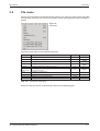
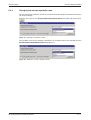
2.3
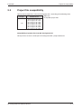
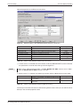
Project file compatibility
Project file compatibility
Open previous project files in the GX Configurator-DP 7 according to the following table:
File type
Software version
*.dp2
ProfiMap 3.0
GX Configurator-DP 4.00
GX Configurator-DP 4.01A
GX Configurator-DP 4.02C
GX Configurator-DP 5.00A
GX Configurator-DP 5.01B
GX Configurator-DP 6.00A
GX Configurator-DP 6.01B
GX Configurator-DP 6.02C
Tab. 2-1:
Compatible project files
Compatibility of project files from GX Configurator-DP
Other previous versions cannot open GX Configurator-DP 7 project databases.
GX Configurator-DP Software Manual
2–3
Software installation
Installation
2.4
Software installation
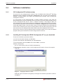
2.4.1
GX Configurator-DP software setup
To install the GX Configurator-DP software from CD-ROM under Microsoft® Windows
98/Windows Me or Windows NT/Windows 2000/Windows XP, you need to have Microsoft®
Windows installed properly. You might need administrator privileges when installing GX
Configurator software.
If an old version of GX Configurator-DP is already installed, uninstall it first. After the
deinstallation please start the installation of the new version. If you want to keep the older version
of GX Configurator-DP please select a different directory and program folder for
GX Configurator-DP 7. If the newer version is installed over the older version into the same directory, this will cause problems with the old entries in the Start 씮 Programs menu. A deinstallation
of the older GXDP version, after the newer version has been installed, will also damage the
newer version. Therefore if you want to correct problems with the older entries please reinstall
new version after uninstalling both the older and the newer GX Configurator-DP versions.
Please close all other running software before installation and do not run other installation
programs during the installation of the GX Configurator-DP software.
2.4.2
Installing GX Configurator-DP/GX Configurator-ST on your hard disk
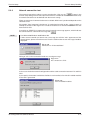
To start the installation, proceed as follows:
햲 If you have not done already, start Windows.
햳 Insert the installation CD-ROM into your CD-ROM drive.
햴 On the Desktop select the Start menu and the Run... command.
햵 Enter: d:\setup.exe
(for "d:" enter the drive letter of YOUR CD-ROM drive)
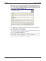
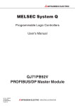
햶 The language selection screens of GX Configurator-DP appear. Choose the required
language.
Fig. 2-1:
Language selection screen
Follow the given instructions that guide you through the installation procedure. Continue
with Next >.
2–4
MITSUBISHI ELECTRIC
Installation
Software installation
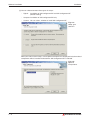
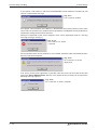
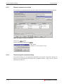
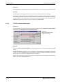
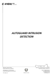
햷 Then you are in the licensing agreement window. Please read these terms carefully.
햸 Click on Yes to agree to the licensing agreement, if you want to proceed or No, if you
want to abort. You are then in the User Information screen. You must enter your name,
company, and the product serial number here.
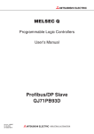
Fig. 2-2:
User information screen of GX Configurator-DP
Click on Next > to proceed to the Registration Confirmation. Here you can check the
registration information you have provided.
햹 Click on Yes to proceed with the installation.
Now you will be asked for the installation path. Enter the destination folder where you
want the GX Configurator-DP software to be installed.
(Default C:\Melsec\GX Configurator-DP).
햺 If you agree with the default setting, just click on Next >. If you want to choose another
destination click on Browse and enter your desired drive and directory.
햻 Now you can select the program folder which you want to have installed. Enter a new
folder name or accept the displayed one and click on Next >.
GX Configurator-DP Software Manual
2–5
Software installation
Installation
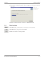
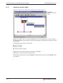
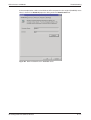
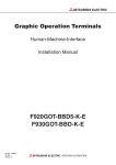
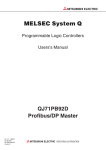
햽 You can choose between three types of setups:
- Typical:
Installation of GX Configurator-DP and GX Configurator-ST
(Default setting)
- Compact: Installation of GX Configurator-DP only
- Custom: You can select, whether to install GX Configurator-ST
Fig. 2-3:
Setup type
selection
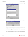
When you select custom setup, a list of optional components is displayed. Only the marked
components will be installed. As default the GX Configurator-ST is selected.
Fig. 2-4:
Optional
Components
2–6
MITSUBISHI ELECTRIC
Installation
Software installation
햾 The installation of GX Configurator-DP will start. Progress bars will inform you about the
setup status.
Fig. 2-5:
Setup status on
progress bar
햿 After the successfull installation, you will see an appropriate message.
2.4.3
Button functions
With the Next button you will leave the current menu and enter the next menu.
With the Back button you go to the previous window.
Cancel button ends the installation procedure.
GX Configurator-DP Software Manual
2–7
Software installation
2–8
Installation
MITSUBISHI ELECTRIC
The Menus
Starting GX Configurator-DP
3
The Menus
3.1
Starting GX Configurator-DP
Select GX Configurator-DP from the Windows Start menu:
Start/Programs/MELSOFT Application/GX Configurator-DP
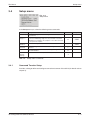
3.2
Main menu
The main menu offers the following pull-down menus. The menu items Actions, Tools, and
Windows are available only if a project file is opened.
Fig. 3-1:
Main menu
The pull-down menus can be selected via mouse or keyboard.
File:
¦F
Setup:
¦S
Actions: ¦ a
Tools:
¦t
View:
¦V
Window: ¦ w
Help:
¦H
The items in the open pull-down menus can be accessed via mouse or keyboard.
The underlined character will start the function. In addition there are some menu items which
may be started using predefined hotkeys.
GX Configurator-DP Software Manual
3–1
Main menu
The Menus
The toolbar just below the main menu contains buttons for an instant access of the most
frequently used functions of GX Configurator-DP. (The MXChange button is only available, if
MXChange actually is installed on your computer):
New
Starting a new project
§N
Open
Opening an existing project
§O
Save
Saving a modified project
§S
Print
Printing the current project
§p
Page Setup
Defining the parameters to be printed
—
Transfer Setup
Defining the network connection type (PC to PLC)
—
MXChange
MXChange support properties
§M
GSD
GSD device database
§g
Help
Getting context help
Help Tool
Getting help on items you click on
—
About
Displaying program information
Tab. 3-1:
3–2
Toolbar icons
MITSUBISHI ELECTRIC
The Menus
3.3
File menu
File menu
After having started the GX Configurator-DP software, this is the first menu to work with. With
the help of this menu you can create a new project, load an existing project, import and export a
project.
Fig. 3-2:
File menu
The menu commands have the following functions.
Command
Purpose
Shortcut
Hotkey
§N
§O
New
Starting a new project
N
Open
Opening an existing project
O
Close
Closing an opened project
C
Save
Saving a modified project
S
§S
Save As...
Saving a modified project with a new name
A
—
Change
Master Type
Changing the type and operating mode (0 or E) of the DP
master in the project
H
§t
Print...
Printing the current project
P
§p
Page Setup
Defining the parameters to be printed
T
—
Project select
Opening one of four recent projects
1,2,3,4
—
Exit
Leaving the software
X
—
Tab. 3-2:
File menu commands
All these menu commands are described in detail on the following pages.
GX Configurator-DP Software Manual
3–3
File menu
3.3.1
The Menus
Command New
The menu command New is used to create a new project.
NOTE
No default module type is selected. Choose a module type before continuing.
First you have to select one of the following module types you intend to setup:
ꔴ
DP master A(1S)J71PB92D (operating mode 0 or E)
ꔴ
DP master QJ71PB92D (operating mode 0 or E)
ꔴ
DP V1/V2 master QJ71PB92V
ꔴ
DP V1 master FX3U-64DP-M
ꔴ
DP slave QJ71PB93D
Fig. 3-3:
Module type selection
Then the graphical network editor appears:
Fig. 3-4:
Graphical network editor
Here you edit the dedicated parameters for the selected network interface module in specific
editors.
At present the A(1S)J71PB92D, QJ71PB92D, QJ71PB93D, QJ71PB92V and
FX3U-64DP-M PROFIBUS/DP network interfaces are supported.
3–4
MITSUBISHI ELECTRIC
The Menus
File menu
The following parameters can be edited:
ꔴ
Master settings (see page 4-3)
ꔴ
Bus parameters (see page 4-8)
ꔴ
Slave settings (see page 4-12)
Chapter 4 of this manual contains a detailed description of the meaning and setting of these
parameters.
3.3.2
Command Open
The menu command Open allows to open a project, which has previously been saved. This
command uses the Windows dialog box for file open operation.
Fig. 3-5:
Opening a project file
The Open dialog box lists only files of the following type:
ꔴ
*.DP2: Project of any master module's PROFIBUS/DP network
ꔴ
*.DPX: Module configuration for QJ71PB93D DP slave modules
This functionality ensures that any GX Configurator-DP 7 PROFIBUS/DP project can be
opened that was generated on any other personal computer running GX Configurator-DP 7.
The shortcuts defined by the Windows dialog box for file open are valid.
NOTE
3.3.3
*.DP-projects generated with software versions previous to MELSEC ProfiMap V. 3.0 cannot
be opened.
Command Close
This menu command closes the active project.
GX Configurator-DP Software Manual
3–5
File menu
3.3.4
The Menus
Command Save
This menu command is used to save a modified project. The project will be saved to the
assigned file name. If no file name exists (e.g. new project) the standard dialog box for Save as
will be opened.
Two different file types are used:
ꔴ
*.DP2: Project of any master module's PROFIBUS/DP network
ꔴ
*.DPX: Module configuration for QJ71PB93D DP slave modules
Saving a DP2 project:
ꔴ
The project is saved with the extension *.DP2 where PROFIBUS/DP network
configuration is stored.
Exporting GSD to project file:
ꔴ
NOTE
3.3.5
The GSD information belonging to a specific project is stored in the project file.
This ensures that all information, which is required to edit the project, is available. It is
therefore no longer required to add GSD information to the local GSD database in order
to open a project.
The project files are saved in a special format with the file extension "*.DP2". These files
increase typically its size, whenever entries are removed or added. Therefore the file will be
compressed by any saving automatically. If you use Microsoft® Windows 98/Windows Me
the compression of the database is not available.
Command Save As
This menu command is used to save a modified project with a new assigned file name. This
command uses the dialog box for file saving.
The file extension *.DP2 or *.DPX is appended automatically depending on the module type
you selected.
3.3.6
Command Change Master Type
Available for *.DP2 projects only. This menu command changes the current project to a
different type of master module.
3–6
MITSUBISHI ELECTRIC
The Menus
3.3.7
File menu
Command Print
Available for *.DP2 projects only. The purpose of this menu command is to print the generated
parameters of the selected network unit, based on a HTML formatting. The information about
what is to be printed is set by the command Page Setup.
The printout function starts the default webbrowser to open the generated HTML file. Detailed
appearance of the printout depends therefore on the browser. The document from the
webbrowser can either be printed or saved to a file, e.g. for including it in the project documentation.
Because the printout accesses the project file, the currently open project must first be saved,
before the settings can be printed. This is done automatically, unless it is a new project, which
has not yet been saved under a file name. In this case the file dialog for saving the project will
be displayed.
Fig. 3-6:
Browser window when Print command is selected
GX Configurator-DP Software Manual
3–7
File menu
3.3.8
The Menus
Command Page Setup
Available for *.DP2 projects only. When you choose Page Setup you can select which parameters will be printed. The selections to be checked depend on the used network interface. Additionally, you can indicate the position of the printed header on the page: top or bottom. If you
select No header the header information will not be printed.
The project header is not part of the project. It is saved in a local file and is the same for all
projects until changed.
Fig. 3-7:
Page setup
3.3.9
Command Recent Files
The pull-down menu shows you the last four used projects. You can open one of them by
pressing the shortcut 1 to 4 or selecting it with the mouse cursor.
3.3.10
Command Exit
You can use this menu command to quit the software. If anything in the current project has
been modified and has not yet been saved the following message appears:
Fig. 3-8:
Save changes to project?
If you want to save the last changes before leaving this software choose
If you choose
3–8
.
all modifications are lost.
MITSUBISHI ELECTRIC
The Menus
3.4
Setup menu
Setup menu
Fig. 3-9:
Setup menu
In the Setup menu you select the following menu commands.
Command
Purpose
Transfer Setup Provides a dialog to define and configure connections between
PC and PLC.
Hotkey
T
MXChange
Support
Provides a dialog to set up the properties of the MXChange
connection. MXChange support is only selectable in case that
MXChange is installed on the computer or on a LAN connected
to the personal computer.
GSD DeviceDatabase
Provides a dialog to access the GSD device database.
Language
Selection
Opens a dialog to select either German or English for the user
interface.
L
Options
Opens a dialog in which the user can change settings related to
the GSD database
O
Auto
Refresh
Settings
Specifies the buffer memory area for the autorefresh
Tab. 3-3:
3.4.1
Shortcut
M
§M
G
§g
A
Setup menu commands
Command Transfer Setup
Provides a dialog to define and configure connections between PC and PLC (for details refer to
chapter 5).
GX Configurator-DP Software Manual
3–9
Setup menu
3.4.2
The Menus
Command MXChange support
Available for *.DP2 projects only. MXChange is an external software package made by
Mitsubishi Electric. An A(1S)J71PB92D or QJ71PB92D PROFIBUS/DP module project can
use MXChange to generate a suitable PLC CPU sequence program at MELSOFT GX IEC
Developer or MELSEC MEDOC plus v2.32 or later. The PLC CPU program update is done
automatically with saving the A(1S)J71PB92D or QJ71PB92D project. For this purpose the
MXChange server must be installed and GX Configurator-DP must be connected to this
server.
This dialog is used to setup the MXChange connection:
Fig. 3-10:
MXChange support
properties
Item
Meaning
MXChange
Connection
Usage
Enable/disable the MXChange function
Shortcut
§M
Local MXChange Specifies that MXChange is installed locally on the same system as GX
Server
Configurator-DP (not in a LAN)
§l
Select Server
Instance
Selects one of up to 16 available servers to connect to
§I
IP Address
Specify the IP address of the MXChange server in the LAN
(ask your network administrator)
User Name
Enter your user name for the MXChange server
Password
Enter your password for the MXChange server
§U
§P
Test
Tests, if a connection to the MXChange server can be established with the
specified settings
§t
Tab. 3-4:
Dialog items MXChange support
You can set the MXChange connection usage for the A(1S)J71PB92D or QJ71PB92D project
by enabling the MXChange Connection Usage check box.
If you prefer a local MXChange server, it is compulsory to install the server on the local PC. The
local MXChange server is selected by enabling the Local MXChange Server check box. For
correct remote MXChange support it is compulsory to install the TCP/IP services of the operating system. The correct IP address of the remote station where the server is located can be
set by disabling the local MXChange server check box. The correct account, subdivided by the
User Name and Password is also compulsory for remote connection usage.
3 – 10
MITSUBISHI ELECTRIC
The Menus
Setup menu
If the MXChange connection is enabled and a project is saved for a master, which is not
supported by MXChange, a warning message is displayed.
Fig. 3-11:
Warning message
GX Configurator-DP Software Manual
3 – 11
Setup menu
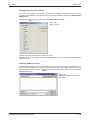
3.4.3
The Menus
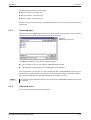
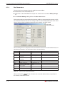
Command GSD Device Database
The command is only available, if no project is currently open. However the GSD database
only effects .DP2 projects. The device database contains information about slave devices from
Mitsubishi or 3rd party manufacturers. This item is used to add or delete devices from the
internal database (so called GSD files from PROFIBUS/DP slave devices), to change settings
in the GSD database, and to import extracted GSD data from other computers running GX
Configurator-DP.
The purpose of this function is to add or delete devices from the internal database of available
devices. The software is distributed with a predefined list of groups, which provide a general
structure for all added slave devices.
Because changes to slave types, which are used in any currently open project, may impact
these projects, the GSD database can only be modified, if no project is open. Therefore the
following message box will be displayed, when trying to open the dialog with a project currently
opened. So first close all open projects.
Fig. 3-12:
Error message
The Device Database can be modified in the following dialog box:
Fig. 3-13:
Device database
When a group is selected in the box Slave Device Group, the model names of the devices
belonging to the selected group are displayed in the lower list box Available Slave Systems.
Upon selecting a device entry in this list box the bitmap, which has been assigned to the
device, is displayed on the right side of the list box.
By double-clicking on the bitmap display or using the button "Replace Bitmap", a file dialog is
opened, in which a file with a new bitmap can be selected. Via the group of radio buttons the
type of bitmap that is replaced can be selected. The GSD standard specifies bitmaps for:
n
n
n
3 – 12
normal operation (this is used in the GX Configurator-DP editor)
diagnostic status
special operations mode
MITSUBISHI ELECTRIC
The Menus
Setup menu
Beneath the bitmap both vendor name and revision string are displayed, as well as the name of
the GSD file and the bitmap file. The so called GSD file describes the features of the slave such
as the supported baud rate and the slave structure (modular slave/compact slave). The
displayed vendor name and revision are included in the GSD file as well.
Please ask the manufacturer of the slave device for the proper GSD file.
Adding devices
A slave device can be added to the database by pressing
. A standard Open File-dialog
appears, so the GSD file can be selected. Each added GSD file is automatically checked for its
data integrity. When leaving the Open-dialog with
, the user will be asked for some
bitmap files (optional). Then the GSD device data is saved in the local GSD device database.
The GSD file itself is no longer required. If the GSD file itself refers to a drawing picture of the
slave device GX Configurator-DP searches automatically for the file. In case that the file is not
found another Open File-dialog is displayed, so the user can select the bitmap file, which he
wants to be linked to the GSD file, representing the corresponding device.
The bitmap file can be supplied by the user from disk. It can be a bitmap file of the data type
*.BMP or *.DIB. However the PROFIBUS/DP standard recommends to provide a bitmap file for
the dedicated slave device with the following restrictions:
Bitmap
Width
70 pixels
Hight
40 pixels
Colors
16
File extension
DIB
Tab. 3-5:
Bitmap restrictions
Only bitmaps that match the requirements in the table above should be used. Other bitmaps
with other sizes and color depths can be used, but will cause a warning message.
Fig. 3-14:
Loading a bitmap for the
device database
GX Configurator-DP Software Manual
3 – 13
Setup menu
The Menus
When both GSD and bitmap file have been selected, you will be asked to confirm the operation.
Fig. 3-15:
Add files to device database?
If you confirm, the contents of both files are read in and an entry is added to the internal device
database for that device. Thereafter, you do not need the actual GSD and bitmap files any
more.
Set Byte Order
With this function you can exchange the upper and lower byte order of user parameter. There
are two types of byte ordering: little endian and big endian.
Normally slaves expect user parameters in "big endian" format. This is the default setting,
when a slave is added to the device database (with the exception of "FX2N modular station").
Only in rare cases this setting should be changed and only after consultation with the slave
vendor.
For a complete list of the devices from the GSD database, click on the
button.
Fig. 3-16:
Selecting byte order
When the selection mark is set, the slave uses "big endian" format. Otherwise it uses "little
endian" format for user parameters.
Select the Slaves with "big endian" format.
3 – 14
MITSUBISHI ELECTRIC
The Menus
Setup menu
Changing the Slave Device Group
DP slaves are grouped in one of the so-called ‘slave families’. The default group is usually
specified in the GSD file. The slave can be assigned to a different group in the Slave Device
Group dialog.
Click on the
button to open the dialog Select Slave Family.
Fig. 3-17:
Select a family
Click on one of the radio buttons to select a family.
If the device group has not been specified in the GSD file, the slave is placed by default into the
‘General’ group.
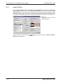
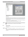
Importing GSD-Extract Files
The GSD-Extract feature allows the transfer of the entire device information of one project from
one personal computer to another without passing on each single GSD file for any
parameterized devices. Click on
to load any existing GSD-extract file or a complete
GSD-database file:
Fig. 3-18:
Selecting a GSD-extract file for
the import
GX Configurator-DP Software Manual
3 – 15
Setup menu
The Menus
Removing devices
A device can be removed from the database by selecting the entry in the left list box and
pressing the
button. This deletes only the entry in the GSD database. It does not
delete the GSD and bitmap files for that device. These files have to be removed manually.
The reason for this is that it is possible to undo the delete function.
NOTE
3.4.4
The entry is immediately removed after clicking on the
it once again later on.
button. However you can add
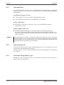
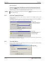
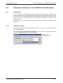
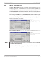
Command Language Selection
Via this menu item you can select either the German or the English version of GX
Configurator-DP.
The following dialog box is opened. To select the german version for example select German
from the drop down list. Confirm your selection by the <OK > button.
Fig. 3-19:
Selecting the language
for the user interface
The following message is displayed:
Fig. 3-20:
GX Configurator-DP has to
be restarted for the
language change
After changing the language selection exit GX Configurator-DP and start it again. Now the
selected language version will be opened.
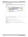
3.4.5
Command Options
Change settings related to the GSD database. This command opens the following dialog
providing access to different options.
Fig. 3-21:
Options dialog
3 – 16
MITSUBISHI ELECTRIC
The Menus
Setup menu
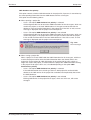
GSD database has priority
This option controls, whether GSD information in the project file, if present, is overwritten by
the corresponding information from the GSD database for the same types.
This option has the following effects:
ꔴ
When opening a project file
- Case 1: The option GSD database has priority is selected
GX Configurator-DP tries to locate the GSD information for the slave types, which are
used in the project, in the local GSD database. If the type cannot be found in the
database, it tries to find the information in the project file. If that fails as well, an error
message is displayed and the project cannot be opened.
- Case 2: The option GSD database has priority is not selected
GX Configurator-DP tries to locate the GSD information for the slave types, which are
used in the project, in the project file itself. If the type cannot be found in the project,
it tries to find the information in the local GSD database. If that fails as well, an error
message is displayed and the project cannot be opened.
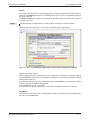
Fig. 3-22:
Error message
ꔴ
When saving a project file
When a project is saved, GXDP adds the GSD information for all slave types, which are
used in the project and for which the GSD information does not already exist in the
project file, to the project file. GSD information in the project file for types, which no
longer are used in the project, is removed from the project file. GSD information existing
in the project file for types still in use, is handled depending on the option GSD
database has priority.
- Case 1: The option GSD database has priority is selected
If the GSD information for a certain type exists in both project file and local GSD
database, the GSD entries in the project file are deleted and replaced by those from
the GSD database.
- Case 2: The option GSD database has priority is not selected
Existing GSD entries in the project file for types, which are still in use, will not be
changed.
GX Configurator-DP Software Manual
3 – 17
Setup menu
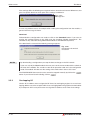
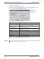
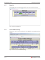
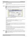
3.4.6
The Menus
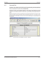
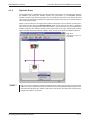
Command AutoRefresh Settings
Available for *.DP2 projects with QJ71PB92D and QJ71PB92V DP masters only. You can
specify the settings for the automatic update and the devices within the CPU. These settings
are stored in the project file. Once the configuration is transferred to the CPU the settings of the
automatic refresh is stored in the IPARAM file of the connected CPU.
In the autorefresh settings editor the buffer memory area for the autorefresh is specified.
Fig. 3-23:
Autorefresh settings editor
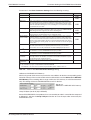
Item
Meaning
Slave Specific
Transfer
Input and output areas of each slave are transferred separately. The CPU start devices can be
specified individually for each slave in the Slave Parameter Settings dialog (see page 4-12).
Advantage:
No wasted CPU devices in Mode 0.
Disadvantage:
Long data transfer time.
Block Transfer
Input and output areas are transferred as one block. CPU start devices can be user-specified.
Advantage:
Short data transfer time.
Disadvantage:
Wasted CPU devices in Mode 0.
Communication
Trouble Area
The contents of the selected area is copied to the specified CPU device.
Extd. Communication Trouble
Area
Slave Status
Area
Cancel
Exit the dialog.
OK
Store the settings in the current project file.
Tab. 3-6:
3 – 18
Items in the autorefresh settings editor
MITSUBISHI ELECTRIC
The Menus
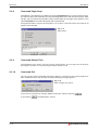
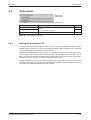
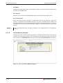
3.5
Actions menu
Actions menu
Fig. 3-24:
Actions menu
In the Actions menu you select the following menu commands.
Command
Purpose
Create POU
Create the POU for copying slave I/O data between the DP master and the
CPU
Shortcut
C
Access to Master Download the configuration of the current project to the module specified
Module
by the current transfer setup.
A
Overlapping I/O
O
Tab. 3-7:
Check all I/O address areas assigned to DP slaves for overlapping regions
Actions menu commands
GX Configurator-DP Software Manual
3 – 19
Actions menu
3.5.1
The Menus
Create POU
POU means Program Organisation Unit and is installed for a GX IEC Developer program. Basically the POU includes FROM/TO instructions to access the buffer memory of the master
module. This POU must be included into the PLC program to have the I/O data of each slave
copied to the given address in CPU memory.
The create POU function is available in projects for A(1S)J71PB92D modules and for
QJ71PB92D modules, if the Autom. Refresh option is not set.
The Create POU function is available for all master modules. However, for QJ71PB92D and
QJ71PB92V only, if the option Autom. Refresh in the Master Settings is not selected.
For further information please refer to the GX IEC Developer Reference Manual.
Automatically create the program code for copying slave I/O data between the DP master and
the CPU.
NOTES
The Create POU function does not handle the error registers, diagnostic and alarm
messages. It also does not check the data transferred, for example in order to set slave
outputs. These parts of the PLC program must be created by the user according to the PLC
application.
For details and example programs, please refer to the corresponding user manual of the
PROFIBUS master.
For importing the created POU in the PLC program, please consult the manual of GX IEC
Developer (GID).
When you choose the menu item Create POU a message appears in which the head adress of
the POU is shown. The head adress is set in the Master Settings dialog.
In case of FX3U-64DP-M the term ‘head address’ equals the slot index of the master.
Fig. 3-25:
Display used head address
If you click on
the Save File As dialog appears, where you select the name of the file,
in which a POU in ASCII format is generated for GX IEC Developer.
Fig. 3-26:
Creating a POU file
After typing in a project name and clicking Save, the file is saved to your selected drive.
NOTE
3 – 20
It is not allowed to start the file name with a number (0 to 9). Otherwise you will get an import
error in GX IEC Developer since the file name is equal to the task and POU name which is
generated. GX IEC Developer does not allow POU names which are beginning with a
number.
MITSUBISHI ELECTRIC
The Menus
3.5.2
Actions menu
Access to Master Module
With this function the generated configuration data can be transferred to the DP master, it
interacts with the network interface module. Therefore, it is necessary that the personal
computer is connected to PLC CPU.
Before you start the transfer:
n
n
Ensure that no other data is transferred from or to the DP master by the PLC CPU
(FROM/TO instructions)
Ensure that the cable is connected correctly to your personal computer and to the PLC CPU.
A message appears when you click on the menu item Access to Master Module, which indicates the connected PLC. Confirm this message with
.
NOTES
If you click on the menu item Access to Master Module, the current project file is saved first.
This makes sure, that any changes made are included in the configuration, which is
downloaded to the PROFIBUS module.
If the master type set in the project does not match the type of the actually connected
module, the user receives a warning.
Fig. 3-27:
Module differs
If the user decides to proceed regardless of the warning, the configuration is converted
online. So if you want to be sure that your configuration is downloaded unchanged, please
always select the correct master type when creating a new project or convert the project to
one of the correct type.
Fig. 3-28:
Configuration download dialog
The path of the current project will be shown.
NOTE
Imposed by MXChange connectivity the length of the path is limited to 127 characters.
Verify
This function verifies the settings of the selected project with the current configuration of the
module. When pressing the Verify button, for PB92D masters a warning is displayed to inform
the user that the dataexchange on the PROFIBUS network will be stopped.
Click OK to continue. The current configuration then is read from the module and compared
with the configuration created from the current project. If both settings match, the following
message box is displayed.
Fig. 3-29:
Message box
GX Configurator-DP Software Manual
3 – 21
Actions menu
The Menus
If the settings differ, the following message box informs about the existance of differences, but
gives no specific details on which parts of the settings are different.
Fig. 3-31:
Message box
In case any problems occur, for example when reading the configuration from the module, a
general error message is shown.
Download
To download the configuration one needs to click on the Download button. If you want to
transfer the updated settings to the CPU mark the checkbox "Update Autorefresh". The
checkbox is only selectable using PROFIBUS modules of the MELSEC System Q.
If the download is successful the following message appears:
Fig. 3-30:
Configuration download
successful
NOTES
By downloading a configuration you stop the data exchange on the DP network.
If you use a A(1S)J71PB92D module the user must set the correct mode with the switch on
the front of the module. The modes are 0 or E for operation mode and 1 for configuration
mode. The module will take over the setting of the mode switch after a CPU reset.
The PROFIBUS/DP data transfer can be started or stopped manually by click on the
button. If you want to leave the dialog, click on
.
3.5.3
Overlapping I/O
Checks all I/O address areas assigned to DP slaves for overlapping regions. In case of overlapping address areas the respective DP slaves are highlighted in the graphical network editor
by a red square. In this case you have to re-assign the I/O address areas in the slave settings.
3 – 22
MITSUBISHI ELECTRIC
The Menus
3.6
Tools menu
Tools menu
Fig. 3-32:
Tools menu
In the Tools menu you can select the following menu commands:
Command
Purpose
Server Administrator
GX Configurator Client
Tools for web-based online access to the network interface
modules
(For details refer to chapter 6)
GX Configurator-ST
Starts GX Configurator-ST
Tab. 3-8:
3.6.1
Shortcut
S
none
C
Tools menu commands
Starting GX Configurator-ST
The menu command GX Configurator-ST is used to start the configuration tool for the ST
modules (Slice Terminal). This menu command is enabled, if GX Configurator-ST is installed,
i.e. the corresponding executable file can be found.
With the GX Configurator-ST you can operate settings and monitor ST1H-PB graphically. It
shows various status of ST1H-PB and slice modules, which include error information. You are
able to use the forced output function via GX Configurator-ST and easily check your wirings.
You can also set parameters of intelligent modules of ST series.
The GX Configurator-ST runs as a separate application with its own entry in the task list and
must be closed separately. However, when GX Configurator-DP is closed, it displays a warning
message in case GX Configurator-ST is still running.
GX Configurator-DP Software Manual
3 – 23
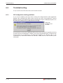
View menu
3.7
The Menus
View menu
In the View menu you can select the following menu commands:
Command
Purpose
Toolbar
Enable /disable toolbar
none
none
Statusbar
Enable /disable status bar
none
none
Zoom In
Increase view size of graphical network editor
none
none
Zoom Out
Decrease view size of graphical network editor
none
none
Tab. 3-9:
Shortcut
Hotkey
View menu commands
These menu commands allow you to select whether the tool bar and the status bar will be
displayed or not. A check mark in front of the commands shows that this function is currently
activated.
3.7.1
Command Toolbar
If the toolbar is enabled, you will find additional buttons for creating documents, opening documents, saving documents or the help menu.
3.7.2
Command Status bar
If this command is enabled, a status bar will be displayed at the bottom of the window informing
you about the selected item and the current status of the project.
3.7.3
Command Zoom In
Select this menu item to increase the view size of the graphical network editor.
3.7.4
Command Zoom Out
Select this menu item to decrease the view size of the graphical network editor.
3 – 24
MITSUBISHI ELECTRIC
The Menus
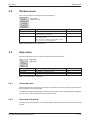
3.8
Window menu
Window menu
This menu provides the standard "window" functions:
Fig. 3-33:
Window menu
Command
Purpose
Shortcut
Cascade
Arranges all open project windows so that they overlap.
none
Arrange Icons
Arranges all minimized windows icons side by side at
the bottom of the main window.
none
1, 2, 3, ...
Switches over to one of several projects that you keep
open simultaneously.
Either click on the loaded project you want to switch
over to or enter the according number.
none
Tab. 3-10: Window menu commands
3.9
Help menu
From the Help menu you can select the following menu commands:
Fig. 3-34:
Help menu
Command
Purpose
Index
Searching for keywords
Shortcut
none
Using Help
Call Windows „Using Help function“
none
About...
Display software release
none
Tab. 3-11: Help menu commands
3.9.1
Command Index
With the help of this function you can search for a keyword. Just type in the term you need information about and you will get help.
In addition you will be supported by a context-sensitive help. If you have opened any dialog box
you can access the help function by pressing the key.
3.9.2
Command Using Help
The purpose of this function is to start the Windows help informing you on how to use the help
system.
GX Configurator-DP Software Manual
3 – 25
Help menu
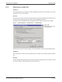
3.9.3
The Menus
Command About...
This function displays information about your software release.
In addition, the about box displays a list of the *.dll files used in order to check the versions of
the different modules.
Fig. 3-35:
Program information
3 – 26
MITSUBISHI ELECTRIC
PROFIBUS/DP Interface
Parameter Setting for PROFIBUS Master Modules
4
PROFIBUS/DP Interface
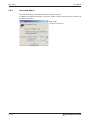
4.1
Parameter Setting for PROFIBUS Master Modules
4.1.1
Introduction and Overview
This chapter describes how to generate the parameter settings for the A(1S)J71PB92D.
Differences to the parameter setting for other PROFIBUS master modules are mentioned
explicitly.
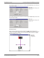
After selecting the command New in the File menu (see chapter 3 for details) choose the
module type PROFIBUS/DP (A(1S)JPB92D).
Fig. 4-1:
DP master selection
The PROFIBUS/DP modules (A(1S)J71PB92D and QJ71PB92D) support an advanced buffer
memory management in 244 byte mode (operating mode E) with larger and more flexible data
telegrams and thus less delay in the sequence program.
The 32 byte mode (operating mode 0) is provided for compatibility reasons with the MELSEC
ProfiMap 1.0 software and with the previous A1SJ71PB92D modules.
GX Configurator-DP Software Manual
4–1
Parameter Setting for PROFIBUS Master Modules
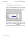
4.1.2
PROFIBUS/DP Interface
Graphical network editor
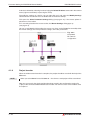
After you have opened a project the graphical network editor appears:
Fig. 4-2:
Graphical network
editor
Within this window you can edit and add devices. For this purpose the current window is
devided into hidden squares. When you click on the window a square appears and you can add
a new device.
The following parameters can be edited:
ꔴ
Master settings
ꔴ
Bus parameters
ꔴ
Slave parameter settings
Double-click on any item to edit its parameters and settings.
Right-click on any item to open a context menu.
The content of the context menu item Actions is identical to the main menu item Actions (refer
to chapter 3).
4–2
MITSUBISHI ELECTRIC
PROFIBUS/DP Interface
4.1.3
Parameter Setting for PROFIBUS Master Modules
Master Settings
To access the master settings from the graphical network editor:
ꔴ
Double-click on the master module or
ꔴ
Right-click on the master module to open the context menu and select Modify Settings
Within the Master Settings the baud rate, different addresses and other parameters for the
PROFIBUS modules can be set.
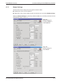
Fig. 4-3:
Master settings for
A(1S)J71PB92D or
FX3U-64DP-M
Fig. 4-4:
Master settings for
QJ71PB92D
GX Configurator-DP Software Manual
4–3
Parameter Setting for PROFIBUS Master Modules
PROFIBUS/DP Interface
For PROFIBUS modules supporting DP V2, i.e. the QJ71PB92V, the Master Settings dialog is
extended by the input of the clock synchronization interval Watchdog for time sync. This
parameter is only displayed in gray for the other PROFIBUS modules:
Fig. 4-5:
Different master settings
for QJ71PB92V
Communications parameters of Master Settings
Parameter
Range
Meaning
Name
—
Shows the project specific name of the master
Baud Rate
9.6 kbps –
12.000 Mbps
Transfer rate for the communication. Define a baud rate that is
supported by all slaves.
FDL address
0–125
FDL address (station number)
Head address on PLC
0×0–0×FE
Module head address on the base unit
Error action flag
—
Output processing after failure. Select this option if you want to
have the outputs shut off in case of error occurence (recommended for drives, inverters etc.).
In practice this means:
After occurrence of any network error all outputs of the network
are turned OFF and no diagnostic information from the slaves is
returned.
Autom. Refresh
(Q series master only)
—
Sets the automatic refresh parameter for the PROFIBUS master
Consistency
(Q series master only)
—
Ensures data consistency
Tab. 4-1:
NOTE
4–4
Communications parameters of Master Settings
If you change the baud rate, power off the slaves. Otherwise the slaves cannot synchronize
with the newly defined baud rate.
MITSUBISHI ELECTRIC
PROFIBUS/DP Interface
Parameter Setting for PROFIBUS Master Modules
Timing parameters of Master Settings
Parameter
Range
Meaning
Min. slave interval
1–65535 x 100 ms
Smallest allowed period of time between two slave poll cycles.
This ensures that the sequence of function requests from the
DP master can be handled by the DP slave. This value is valid
for all installed slaves. The slowest slave defines this value.
Polling timeout
1–65535 x 1 ms
In case of master-master communication this parameter specifies the max. amount of time it may take the requestor to fetch
the response.
Data control time
1–65535 x 10 ms
This parameter defines the period of time during which the
master module notifies the slave operation status. This time is 6
times longer than the watchdog control of slaves.
Watchdog
ON/OFF
This checkbox enables the watchdog checking in all slaves.
Slave Watchdog time
1–65025
When the checkbox Watchdog is checked (ON), this specifies
the maximum time without communication, after which the slave
will regard the connection to the master to be broken.
If the slave supports DPV1, the unit will automatically be set to
either "10 ms" or "1 ms", depending on the setting of the
"Watchdog Timebase" flag in the user parameters of the slave.
NOTE:
The unit is only changed, if the WDT option is enabled specifically for a slave. If WDT has been enabled via the master, all
slaves must use the default timebase of 10ms.
Watchdog for time sync.
(QJ71PB92V only)
0–65535 x 10 ms
This parameter specifies the interval, in which the time master
broadcasts the current system time.
Tab. 4-2:
Timing parameters of Master Settings
If you want to use the factory set default values click on
the standard values.
and all values are set to
Autom. Refresh (Q series master only)
The automatic refresh function must be activated to enable the consistency function (see
below). The automatic refresh function sets the automatic refresh parameter for the
PROFIBUS master in the parameter file stored in the System Q CPU. This file manages
parameter data for all special function modules of the System Q.
With set automatic refresh parameter the input, output, and diagnostic/ communication areas
of the PROFIBUS master are transferred to a user definable area in the CPU. This way, they
can be accessed directly and fast without using a FROM/TO instruction.
The parameter file for the PROFIBUS master corresponding to a specific GX Configurator-DP
project can be setup and generated in the dialog Setup/AutoRefresh (see page 3-18).
The autorefresh settings in the CPU can be updated together with the download of the configuration to the PROFIBUS module (see page 3-21 and chapter 6).
NOTE
If you create a new Q series master project, the Autom. Refresh option is set by default.
For details refer to the hardware manual of the Q series master module.
GX Configurator-DP Software Manual
4–5
Parameter Setting for PROFIBUS Master Modules
PROFIBUS/DP Interface
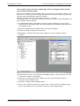
Use automatic refresh function in combination with the intelligent function module
utility of the GX (IEC) Developer:
Because the intelligent function module utility will overwrite any autorefresh settings in the
PLC CPU, it is necessary to read existing settings from the CPU first in order to preserve the
settings made for PROFIBUS Q series master module.
Note that instead of the name of the profibus-module a "*" is shown.
The following steps are required, if autorefresh settings are used for both PROFIBUS and
other intelligent function modules:
햲 For PROFIBUS modules add/update autorefresh settings directly in the PLC CPU by
selecting the corresponding option when downloading the PROFIBUS configuration with
GX Configurator-DP.
햳 Open the "Intelligent funtion Module utility" in GX (IEC) Developer.
햴 Read the existing configuration from the PLC.
햵 Add/update autorefresh settings for other modules (e.g. A/D- and D/A-converter
modules).
햶 Delete obsolete entries, for example for PROFIBUS modules, which have been removed
or placed to a different head address.
햷 Overwrite the existing autorefresh settings on the PLC with the settings from the
"Intelligent function Module utility".
햸 Leave the "Intelligent function Module utility".
햹 You can now check the autorefresh settings in the "Current Autorefresh Settings" page,
which is accessible from the web browser interface of GX Configurator-DP.
4–6
MITSUBISHI ELECTRIC
PROFIBUS/DP Interface
Parameter Setting for PROFIBUS Master Modules
Consistency (Q series master only)
The automatic refresh function (see above) must be activated to enable the consistency
function. Otherwise e.g. output data for a slave may be set in the slave in several segments and
not in a single PROFIBUS cycle.
The consistency function can be activated for System Q CPUs from OS version B (Sep. 2000).
The consistency function interlocks simultaneous access to the buffer memory by the CPU
and the DP master. This way, data consistency especially required for high-speed applications
is automatically ensured.
This interlock mechanism slightly decreases the transfer speed. Therefore, only enable the
consistency function, if you require data consistency.
For details refer to the hardware manual of the Q series master module.
GX Configurator-DP Software Manual
4–7
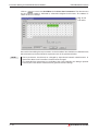
Parameter Setting for PROFIBUS Master Modules
4.1.4
PROFIBUS/DP Interface
Bus Parameters
To access the bus parameters from the graphical network editor:
ꔴ
Double-click on the PROFIBUS line or
ꔴ
Right-click on the PROFIBUS line to open the context menu and select Modify Settings
or
ꔴ
In the Master Settings dialog click on the Bus. Param. button
This function allows to select the baud rate and to modify any parameters like timeouts, which
are related to the baud rate. The last settings made are stored independently for each baud
rate, so that by selecting a different baud rate these settings are shown again.
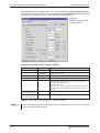
Fig. 4-6:
Bus parameters
General timing factors are displayed in recalculated form based on the selected baud rate and
absolute time durations. The conversion factors are the following:
Item
Meaning
Range
Remark
Baud Rate
Transfer rate
see selection
Must be supported by all slaves
T_sl
Slot time
37–16383 x t_bit
Max. Interval to wait for response
min T_sdr
Min. Station delay of
responder
11–1023 x t_bit
max T_sdr
Max. Station delay of
responder
35–1023 x t_bit
T_qui
Quiet time
0–127 x t_bit
T_set
Setup time
1–255 x t_bit
T_tr
Target rotation time
256–16777215 x t_bit
GAP factor
Controls the GAP update
time (T_gud )
1–100
HSA
Highest station address
2–126
Max. retry
limit
Max. number of retries
1–7
Tab. 4-3:
T = 0, if no repeater present
Items in Bus Parameter dialog
When pressing the
button all values are set to their default values, especially for
the currently selected baud rate.
4–8
MITSUBISHI ELECTRIC
PROFIBUS/DP Interface
NOTE
Parameter Setting for PROFIBUS Master Modules
If you change the baud rate of an existing PROFIBUS/DP network, power off the slaves.
Otherwise the slaves cannot synchronize with the newly defined baud rate.
The inputs are checked against the input limits when leaving the dialog with the
button. Additionally the following consistency checks are performed:
NOTE
ꔴ
min T_sdr < max T_sdr
ꔴ
T_qui < min T_sdr
ꔴ
max T_sdr < T_sl
ꔴ
T_sl < T_tr
If you are not an experienced PROFIBUS network administrator the Bus Parameters should
not be changed except in the following cases:
a) More than 15 slave stations are implemented (target rotation time has to be calculated
again).
b) The network consists of more than 1 master (target rotation time has to be calculated
again).
c) PROFIBUS/DP and PROFIBUS/FMS operation are used in mixed mode
(FMS parameters have to be defined)
For the correct parameter setting of the target rotation time TTR (t_tr) please refer to the
PROFIBUS standard DIN19245 part 3. However, it is important that the target rotation time is
large enough to enable the master module to poll each defined slave once per token cycle.
GX Configurator-DP Software Manual
4–9
Parameter Setting for PROFIBUS Master Modules
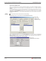
4.1.5
PROFIBUS/DP Interface
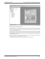
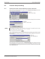
Insert DP Slave
In the graphical network editor right-click on the PROFIBUS line to open the context menu.
Select Insert DP-Slave to access the GSD Device Database. After having selected a Slave
Device Group, a list of all slave models assigned to the respective group is displayed. For the
selected slave the vendor and revision string, the bitmap and the path of the GSD file and the
bitmap file are displayed (refer to the section Device Database in chapter 3 for further details).
Fig. 4-7:
Inserting a DP slave from the
device database
When a model is selected and the
Settings dialog appears.
4 – 10
button has been pressed, the Slave Parameter
MITSUBISHI ELECTRIC
PROFIBUS/DP Interface
4.1.6
Parameter Setting for PROFIBUS Master Modules
Duplicate Slave
The configuration of a modular DP slave like the ST1H-PB involves several steps like selecting
the modules and setting the module specific user parameters. If a PROFIBUS network
includes several slaves of the same type, this may require to repeat the same actions for each
slave again. To simplify the procedure it is possible to add an exact copy of an already existing
slave to the project again.
Select a slave and press the right mouse button to display the slave-specific context menu.
This menu contains the entry Duplicate Slave. Click on this menu item to get an additional
slave with the same configuration (selected modules, user parameters etc.) inserted into the
Profibus network. This avoids inserting a new slave of the same type, selecting the modules
again and adjusting the parameter settings, which is both error-prone and labour-intensive.
Fig. 4-8:
Inserting a copy of a
DP slave
NOTE
The new slave has identical settings compared to the original one. For this reason the FDL
address has to be adjusted and the slave name must be changed after duplicating the slave.
Otherwise the identical FDL address and name in two slaves will violate the restriction of a
unique FDL-address and name.
GX Configurator-DP Software Manual
4 – 11
Parameter Setting for PROFIBUS Master Modules
4.1.7
PROFIBUS/DP Interface
Slave Parameter Settings
To access the slave parameter settings from the graphical network editor:
ꔴ
Double-click on a DP slave or
ꔴ
Right-click on a DP slave to open the context menu and select Modify Settings
Fig. 4-9:
Slave parameter settings
for the PROFIBUS
module A(1S)J71PB92D
For the other PROFIBUS modules there is an additional Swap I/O Bytes function:
Fig. 4-10:
Slave parameter settings
In the upper part of the window, the name of the selected device and the vendor name are
displayed.
If you have selected a wrong device, you can leave this window with the
then jump back to the Network Configuration menu.
button. You
When the correct model is displayed you have to set the parameters listed in the following
table.
When pressing the
4 – 12
button all values are set to their default values.
MITSUBISHI ELECTRIC
PROFIBUS/DP Interface
Parameter Setting for PROFIBUS Master Modules
Parameters in the Slave Parameter Settings have the following meaning:
Item
Purpose
Name
The name of the slave can be defined. This is for documentation purpose only.
¦N
FDL_address
This item is used to define the station address of the slave.
¦D
Watchdog
Click on the white box or type the shortcut if you want to use the watchdog
timer for this device. The check box enables the watch dog control of the slave.
The slave will check whether the master was in communication with the slave
within the defined watchdog time. If the watchdog time is exceeded the outputs
are turned to the save state.
¦W
If you have selected the Watchdog function you must define the watchdog time
interval of the slave. Make sure that the data control time in the Master Parameter setting is 6 times longer than the slaves watchdog time.
¦T
min T_sdr
This is the minimum waiting time for a DP slave until it is allowed to send response frames to the DP master. Do not change this value.
¦M
Group identification number
PROFIBUS/DP allows to transmit control commands (such as sync or freeze)
from the master to one slave, a group of slaves or all slaves at the same time.
The control commands are based on multicast function. This means that slaves
with the same group number operate in a synchronized way with each other. A
slave can belong to several groups. You can use the boxes to allocate the group
for the slave.
¦G
Watchdog time
Shortcut
Active
When this option is activated you get information whether the defined slave really exists (max. 60 slaves are possible). With this function you can define
slaves which are not really existant but should be added physically later on.
Sync햲
If this option is activated a synchronous switching of all outputs in the network
(for simulation of a time shifted END instruction) is possible.
Freeze햲
If this option is activated a synchronous switching of all inputs in the network
(for simulation of a time shifted END instruction) is possible.
DP V1 support
enabled햳
If this option is activated the master will be informed that the respective slave
will support DP V1 for the MS1 connections. This enables the button for opening the dialog for DP V1/V2 parameters.
DP V1/V2 Slave This button opens the dialog for DP V1/V2 parameters.
Parameters햳
햲
햳
only available for slaves where this function is possible (stated at GSD file)
only available for projects for QJ71PB92V and FX3U-64DP-M
The GSD file of the slave must contain the keyword "DPV1_Slave" with the value "1".
Tab. 4-4:
Items in the Slave Parameter Settings dialog
Addresses in MELSEC CPU Memory
After having made all the necessary entries the start address for devices corresponding to the
I/O buffer memory of the master module must be defined in the section Adresses in MELSEC
CPU Memory. The according device range used in the CPU memory is calculated automatically. This dialog will match PROFIBUS/DP data to PLC devices.
Fig. 4-11:
Addresses in MELSEC CPU memory
Swap I/O Bytes (not for A(1S)J71PB92D)
Several PROFIBUS/DP slave products have a reversed byte order in a word device compared
to Mitsubishi. Activate the Swap I/O Bytes function to have the byte order reversed by the
PROFIBUS master.
GX Configurator-DP Software Manual
4 – 13
Parameter Setting for PROFIBUS Master Modules
PROFIBUS/DP Interface
DP V1/V2 Slave Parameters
To access the DP V1/V2 slave parameters:
ꔴ
Check the option DP V1 support enabled in the Slave Parameter Settings menu and
click on the button DP V1/V2 Slave Parameters.
Fig. 4-12:
DP V1/V2 Slave
Parameters
The parameters have the following meaning:
Item
Purpose when checked
Ignore AutoClear
AutoClear is ignored.
Initialize slave when failing to
respond
The slave will be initialized when it fails in responding.
Watchdog timebase 1ms
The slave interpretes the given value for watchdog time as a multiple of
1 ms instead of 10 ms
‘Fail Safe’ function enabled
The slave works in the ‘FailSafe’ mode.
Slave-specific check of cfg_data
The slave applies a slave-specific check to the configuration data sent by
the master.
Update Alarm
The slave can send ‘Update’ alarms.
Status Alarm
The slave can send ‘Status’ alarms.
Manufacturer Specific Alarm
The slave can send ‘Manufacturer Specific’ alarms.
Diagnostic Alarm
The slave can send ‘Diagnostic’ alarms.
Process Alarm
The slave can send ‘Process’ alarms.
Pull/Plug Alarm
The slave can send ‘Pull/Plug’ alarms.
Allow max. one alarm of each type
Only one alarm of each type can be sent.
Tab. 4-5:
NOTE
4 – 14
Items in the DP V1/V2 Slave Parameters dialog
If the watchdog time has been set for all slaves via the master parameter settings, the option
for setting the WDT timebase to 1 ms is disabled.
MITSUBISHI ELECTRIC
PROFIBUS/DP Interface
Parameter Setting for PROFIBUS Master Modules
Extended User Parameters
To access the extended user parameters from the graphical network editor:
ꔴ
Right-click on a DP slave to open the context menu and select User Parameters or
ꔴ
In the Slave Parameter Settings dialog click on the User Param. button
The user parameters for the slave device can be defined individually. In case that the products
GSD file supports extended user parameter click on
to access the following dialog
box.
Fig. 4-13:
Extended user
parameters
The Extended User Parameters are not standardized but depend on the slave. The purpose
of the user parameters is to parameterize the individual slave. For example the slave is an
analog input device and the operating mode of the input channel is to be parameterized by the
startup of PROFIBUS/DP. Then you can specify this operating mode here. Click on the value
setting if you want to change and select the desired setting. All supported settings are
displayed in clear but can also be changed within a simple hex editor. If you prefer to edit
unsigned integer values as hex values, check the
box.
The width of the columns can be varied by placing the mouse pointer between two table
headings until it changes to a double-arrow and then clicking and dragging to the left or to the
right.
GX Configurator-DP Software Manual
4 – 15
Parameter Setting for PROFIBUS Master Modules
PROFIBUS/DP Interface
Click on
to access the Hex Editor for the Slave User Parameters. The relevant area
for the selected module is indicated by coloured background and arrows. The address is
shown in clear as "tool tip".
Fig. 4-14:
Hex editor
Be careful when editing these parameters via the hex editor. You should have a detailed slave
documentation by the manufacturer to prevent errors in the parameterization.
NOTE
4 – 16
These parameters should only be changed by experienced network administrators. In
general the Slave User Parameters should not be changed.
If no extended user parameters are available at the slaves GSD file, this dialog is opened.
Consult your slave device manufacturer to generate correct settings.
MITSUBISHI ELECTRIC
PROFIBUS/DP Interface
Parameter Setting for PROFIBUS Master Modules
Slave Module Selection
When an I/O module is selected the type of module can be defined after clicking on
This button is enabled depending on the GSD file of the selected PROFIBUS/DP slave.
.
The following dialog box is displayed:
Fig. 4-15:
Slave module
selection
PROFIBUS/DP offers the possibility to support modular slave devices. The slave device is the
summary of all modules installed to the slave. The GSD file includes all selectable modules for
the slave device. Mark a module in the right list of Installed Modules. Then select a module in
the left list of Available Modules and press the Add before or Add after button. If you press
the Add before button, the module is inserted before the selected entry in the Installed
Modules list or, in case Add after button is pressed, the module is inserted after the marked
module in the Installed Modules list. To remove a module from the Installed Modules list,
select the module and press the Remove button. The slot number they are added to is shown
beside the installed modules. When you want to append a module at the end of the list, no
module must be selected in the Installed Modules list, because otherwise the new module
will be inserted before the selected one. To remove the selection, remove the selected module.
Then no module is selected anymore and modules can be appended at the end of the list.
GX Configurator-DP automatically determines the maximum possible number of modules per
slave, the maximum allowed length of the data telegram depending on the installed modules,
and the maximum user parameter data size. It also calculates the number of I/O bytes used by
the modules you install and user parameter bytes thus preventing you from exceeding the
supported length of telegram.
If you have created a new Profbus DP project with a 32-byte array (operation mode 0), it is not
allowed to have more than 32 input bytes plus 32 output bytes.
In case you exceed the maximum telegram length GX Configurator-DP will ask you to reduce
the amount of installed modules.
After cklicking
NOTE
the Slave Parameter Settings dialog appears again.
After having made all settings in the Slave Modules windows you have to define the start
address in the CPU memory in the dialog box Slave Parameter Settings.
GX Configurator-DP Software Manual
4 – 17
Parameter Setting for PROFIBUS Master Modules
PROFIBUS/DP Interface
Generic Slave Module Type
Some slave GSD files do not contain module descriptions, but require the module configuration data (‘cfg_data’) to be constructed in the configuration tool via a so-called ‘Universal
Module’.
If a slave GSD file does not contain module definitions, GX Configurator-DP displays the entry
Universal in the Slave Modules dialog. One or more universal module entries can be added
to the Installed Modules list. The maximum input/output size for each module is 16 words or
32 bytes.
NOTE
Ensure that the slave can work with the made settings.
The following shows a slave with three selected Universal modules.
Fig. 4-16:
Slave module
selection of a
universal module
When a Universal module entry in the Installed Module list is double-clicked, the Universal
Module Settings dialog is opened and the properties of the selected universal module, i.e.
consistency, input and output size, can be changed.
Fig. 4-17:
Universal Module Settings
4 – 18
MITSUBISHI ELECTRIC
PROFIBUS/DP Interface
Parameter Setting for PROFIBUS Master Modules
If the module should only have an input area, select the option Inputs only and the field for the
output length is hidden.
Fig. 4-18:
Universal Module Settings with
inputs only
If the module should only have an output area, select the option Outputs only and the field for
the input length is hidden.
Fig. 4-19:
Universal Module Settings with
outputs only
DP Network Layout
When the device configuration has been entered click
and the bitmap for that
model is inserted into the graphical network layout. The bitmap of the installed slave device
is shown in the window. In addition the name and the FDL address (defined in the Slave
Parameter Setting dialog) is stated.
Fig. 4-20:
DP network
configuration
GX Configurator-DP Software Manual
4 – 19
Parameter Setting for PROFIBUS Master Modules
PROFIBUS/DP Interface
A device is deleted by selecting it and activating the Delete DP-Slave command in the context
menu (right mouse button) or pressing the µ key.
To modify the settings of a device, you can right-click on it and select the Modify Settings
command from the context menu or double click on the device bitmap.
This opens the Slave Parameter Settings dialog (see page 4-12), if the mouse pointer is
placed on a slave station.
If it is currently placed on the master station, the Master Settings dialog pops up
(see page 4-3).
You can as well double-click on either the master, any slave, or the RS485 line to modify either
the master settings, the slave parameter settings, or the bus parameters.
Fig. 4-21:
Completed
DP network
configuration
4.1.8
Project transfer
When the whole network creation is complete, the project should be saved with the help of the
File menu.
NOTE
When you select Save instead of Save as ... the former saved project will be overwritten!
Now you can transfer the whole configuration data stored in the configuration project file
(*.dp2) to the connected PROFIBUS master module. For online access to the modules refer
to chapter 6.
4 – 20
MITSUBISHI ELECTRIC
PROFIBUS/DP Interface
Parameter Setting for QJ71PB93D Slave Modules
4.2
Parameter Setting for QJ71PB93D Slave Modules
4.2.1
Introduction
The QJ71PB93D is a PROFIBUS/DP V0 slave module for System Q PLCs. It enables a DP
master to access devices in a System Q CPU. System Q PLCs become powerful sub-stations
accessible easily via the PROFIBUS/DP. The QJ71PB93D is configured partially by the DP
master and by the configuration tool GX Configurator Client which is integrated in GX
Configurator-DP.
The project file for the QJ71PB93D slave module is an XML file (not *.dp2 as for PB92D master
modules).
4.2.2
Parameter setting
This chapter describes how to generate the parameter settings for the PROFIBUS slave
module QJ71PB93D.
After selecting the command New in the File menu (see chapter 3 for details) choose the
module type PROFIBUS/DP Slave (QJ71PB93D).
Fig. 4-22:
Module selection
GX Configurator-DP Software Manual
4 – 21
Parameter Setting for QJ71PB93D Slave Modules
PROFIBUS/DP Interface
After you have opened a project the following dialog for the slave parameter settings appears:
Fig. 4-23:
Slave parameter settings
Here you specify the following parameter settings:
Item
Purpose
FDL_address
This item is used to define the station address of the slave.
Autom.
Refresh
Enable, Consistency. See details below
Input Size
Specifies the size of the input area in units of words
N
Output Size
Specifies the size of the output area in units of words
U
Input
CPU Device
Specifies the input device and its start address in the CPU. The according device
range used in the CPU memory is calculated automatically.
I
Output
CPU Device
Specifies the output device and its start address in the CPU. The according device range used in the CPU memory is calculated automatically.
O
Tab. 4-6:
Shortcut
F
E, C
Items in the slave parameter settings dialog
Autom. Refresh
The automatic refresh function sets the automatic refresh parameters for the PROFIBUS slave
QJ71PB93D in the parameter file stored in the System Q CPU. This file manages parameter
data for all special function modules of the System Q.
With set automatic refresh parameter the input and output of the PROFIBUS slave are transferred to a user definable area in the CPU. This way, they can be accessed directly and fast
without using a FROM/TO instruction.
For details refer to the hardware manual of the QJ71PB93D slave module.
4 – 22
MITSUBISHI ELECTRIC
PROFIBUS/DP Interface
Parameter Setting for QJ71PB93D Slave Modules
Use automatic refresh function in combination with the intelligent function module
utility of the GX (IEC) Developer:
Because the intelligent function module utility will overwrite any autorefresh settings in the
PLC CPU, it is necessary to read existing settings from the CPU first in order to preserve the
settings made for PROFIBUS module QJ71PB92D
Note that instead of the name of the profibus-module a "*" is shown.
The following steps are required, if autorefresh settings are used for both PROFIBUS and
other intelligent function modules:
햲 For PROFIBUS modules add/update autorefresh settings directly in the PLC CPU by
selecting the corresponding option when downloading the PROFIBUS configuration with
GX Configurator-DP.
햳 Open the "Intelligent funtion Module utility" in GX (IEC) Developer.
햴 Read the existing configuration from the PLC.
햵 Add/update autorefresh settings for other modules (e.g. A/D- and D/A-converter
modules).
햶 Delete obsolete entries, for example for PROFIBUS modules, which have been removed
or placed to a different head address.
햷 Overwrite the existing autorefresh settings on the PLC with the settings from the
"Intelligent function Module utility".
햸 Leave the "Intelligent function Module utility".
햹 You can now check the autorefresh settings in the "Current Autorefresh Settings" page,
which is accessible from the web browser interface of GX Configurator-DP.
GX Configurator-DP Software Manual
4 – 23
Parameter Setting for QJ71PB93D Slave Modules
PROFIBUS/DP Interface
Consistency
The consistency function can be activated for System Q CPUs from OS version B (Sep. 2000).
The consistency function interlocks simultaneous access to the buffer memory by the CPU
and the DP slave. This way, data consistency especially required for high-speed applications is
automatically ensured.
This interlock mechanism slightly decreases the transfer speed. Therefore, only enable the
consistency function, if you require data consistency.
For details refer to the hardware manual of the QJ71PB93D slave module.
NOTE
4.2.3
Only the FDL address, the autorefresh flag, and the consistency flag are transferred to the
DP slave. The size settings in the slave parameter settings dialog are relevant only for the
data exchange between DP slave and System Q CPU via autorefresh.
Project transfer
When the slave parameter configuration is complete, the project should be saved with the help
of the File menu.
NOTE
When you select Save instead of Save as ... the former saved project will be overwritten!
Now you can transfer the whole configuration data stored in the configuration project file
(*.dpx) to the connected PROFIBUS slave module. For online access to the modules refer
to chapter 6.
4 – 24
MITSUBISHI ELECTRIC
Transfer Setup
Introduction
5
Transfer Setup
5.1
Introduction
GX Configurator-DP is capable of downloading PROFIBUS/DP configuration data to the
PB92D master module via serial (RS232/RS422), USB, MELSEC Ether net or
MELSECNET/10. The master module can be configured via the CPU port of a local or remote
MELSEC PLC or via an Ethernet connection to your personal computer (PC).
NOTE
The transfer setup is only available in master projects, not in slave projects.
For successful network settings you should be familiar with the characteristics of
MELSEC Ethernet and MELSECNET/10 and refer to the corresponding manuals.
5.1.1
Supported connection types
PC (GX Configurator-DP) to PLC
n
n
n
n
n
n
n
NOTE
COM port to System Q CPU (RS232 or USB CPU port)
COM port to QnA-CPU (RS422 CPU port)
Ethernet board to QE71 (QnA Ethernet board)
Ethernet board to QJ71E71 (Qn Ethernet board)
COM port to A-CPU (RS 422 CPU port) only locally, no network connection
ACPU via MAC
COM port to FX3U-CPU (RS422 CPU port)
For access to QnA and System Q CPU via MAC select direct connection to CPU port. The
PC-side serial port on the MAC must be set to the same settings as the CPU-side port, i.e. 8
databits, 1 stopbit, odd parity and baud rate as set in the respective GX Configurator-DP
transfer path. You can set this parameters with the E-Designer. Select the item "Comm
Settings..." in the "Transfer" menu of the E-Designer. For details refer to the Operation
Manual of the E-Designer.
PLC to PLC
n
n
None (local CPU is the PROFIBUS master host in general)
MELSECNET/10 (PROFIBUS master is located on remote CPU rack)
GX Configurator-DP Software Manual
5–1
Introduction
5.1.2
Transfer Setup
Supported network configurations
GX Configurator-DP 7 supports MELSEC Ethernet and MELSECNET/10 connections with the
following restrictions.
Restrictions:
n
n
n
n
n
No support for combined MELSECNET/10 and MELSECNET/II systems
No support for MELSECNET/II, MELSECNET/B
No support for MELSECNET/10 multi-layer systems
No support for MELSECNET/10 remote network systems
Support for AnN, AnA, AnU CPU port access only as local host
(no network connection)
Combination of AnU and QnA(S) CPUs in a network
n
n
n
5–2
If GX Configurator-DP is connected to a QnA(S) station in a MELSECNET/10 network,
the QnA(S) CPU must be switched to A mode by hardware switch, if transfer to an AnU
is required.
If QnA(S) CPUs are existing in a MELSECNET/10 network, a QnA(S) CPU must be the
control station.
If QnA(S) and AnU CPUs are existing in a MELSECNET/10, a QnA(S) CPU must be the
control station. The AnU CPU can only be accessed from a QnA(S) CPU with hardware
switch in A mode.
MITSUBISHI ELECTRIC
Transfer Setup
Transfer Setup Handling
5.2
Transfer Setup Handling
5.2.1
Opening the transfer setup and defining a network connection
Click on the Transfer Setup button in the toolbar or select Setup/Transfer Setup from the main
menu to open the transfer setup.
Fig. 5-1:
Select transfer setup
Define a network name. The network name is used to identify the settings for one transfer path
and must therefore be unique.
Fig. 5-2:
Define a network name
NOTE
The length of the network name is limited to 32 characters. The network name can only
contain alphanumeric characters and "_", "-", " ", ",", "(", ")".
Enter a network name and click on
.
Select a MELSECNET unit your PC is connected to. You can either access the PLC via the
CPU port with a special programming cable or via an Ethernet board. Below the serial connection is selected.
Fig. 5-3:
Select MELSEC unit
After selecting the network module, define the MELSEC network across which the host CPU
of the PROFIBUS master module can be accessed. The PROFIBUS master module can either
be installed together with the target CPU on the same rack or on a remote CPU rack accessible
across MELSECNET/10.
GX Configurator-DP Software Manual
5–3
Transfer Setup Handling
Transfer Setup
Below the local installation is selected.
Fig. 5-4:
Select the network type
NOTE
If you have connected a "A CPU" to the PC, you can only choose the local installation ("local
PLC contains the master module"). In this case, the dialog in fig. 5-4 doesn't appear.
The CPU port network connection is defined using default values. Now you can edit the values
directly in the network properties table.
Network properties for the CPU port connection
5–4
Fig. 5-5:
Default values of the defined network connection
Fig. 5-6:
Transfer Setup for a server connection
MITSUBISHI ELECTRIC
Transfer Setup
Transfer Setup Handling
Item
Meaning
Shortcut
Change Network Symbolic
Change the name of the selected network connection.
Name
¦S
Search Network by
Symbolic Name
Search for a network connection by name.
¦N
Local computer is the
server
Define the local computer as the server. The server
address is localhost.
Server name or IP adress
Specify the server name or the IP address of a server. The
GX Configurator-DP server must be started manually on
the computer. The user interface is a web page access
from the default webbrowser. This item is only available if
you disable "Local computer is the server" checkbox.
Test PLC
If "Local computer is the server" is enabled:
test connection to PLC
¦T
Test Server
If "Local computer is the server" is disabled:
test connection to the server (not to the PLC attached to
the server!)
¦T
Define
Define a new network connection.
Delete
Delete the selected network connection.
OK
Leave this dialog and set the current transfer setup for the
project.
Cancel
Leave the dialog and discard any changes.
Export
Write the current transfer setup into a XML file.
Tab. 5-1:
¦E
¦D
¬
°
¦X
Items in the transfer setup dialog
Parameters in the Transfer Setup have the following meaning:
Item
Purpose
Slot number
Specify the Slot in which the selected module is installed.
0–63
Serial Transfer Speed
Select the serial baud rate for the connection between PC
and PLC. Selection range depends on CPU type.
9600 bps
19.2 kbps (default)
38.4 kbps
57.6 kbps
115.2 kbps
Serial Port Number
Select the serial port number of your PC connected to the
PLC CPU.
Target PLC Family
Display the connected PLC serie.
Tab. 5-2:
햲
Range
1–10
Fixed 햲
Items in the parametrize network
If "local access" is selected, this cell is fixed. If a 2nd-level MELSECNET has been selected,
this parameter is used to select the type of the target PLC.
The CPU port network connection is defined using default values. Now you can edit the values
directly in the network properties table.
GX Configurator-DP Software Manual
5–5
Transfer Setup Handling
5.2.2
Transfer Setup
Defining an Ethernet connection
Define a new network connection by click on the
button. The network name is used to
identify the settings for one transfer path and must therefore be unique.
NOTE
The length of the network name is limited to 32 characters. The network name can only
contain alphanumeric characters and "_", "-", " ", ",", "(", ")".
Select the MELSEC unit your PC is connected to. You can either access the PLC via the CPU
port with a special serial programming cable or via an Ethernet board. Below the Ethernet
connection is selected.
Fig. 5-7:
Select Ethernet board
Select the MELSEC network across which the host CPU of the PROFIBUS master module
can be accessed. The PROFIBUS master module can either be installed together with the
target CPU on the same rack or on a remote CPU rack accessible across MELSECNET/10.
Below the local installation is selected.
Fig. 5-8:
Select the network type
NOTE
If you have connected a "A CPU" to the PC, you can only choose the local installation ("local
PLC contains the master module"). In this case, the dialog in fig. 5-8 doesn't appear.
The Ethernet network connection is defined using default values. Now you can edit the values
directly in the network properties table.
5–6
MITSUBISHI ELECTRIC
Transfer Setup
Transfer Setup Handling
Network properties for the Ethernet connection
Fig. 5-9:
Item
Purpose
Slot number
Specify the slot in which the selected module is installed
0–63
Target Network No.
Specify the network number of the Ethernet module
1–239
Target Station No.
Specifiy the station number of the Ethernet module
Port Number PC Side
Specify the port number from the PC
IP-Address of E71
Specify the IP address of the Ethernet board
Station No. PC Side
Specify the station number of the PC
Target PLC Family
Display the connected PLC serie
Tab. 5-3:
햲
NOTE
Default values of the defined Ethernet network connection
Range
0–64
256–65535
a. b. c. d or hostname
0–64
Fixed 햲
Items in the Ethernet network (local access)
If "local access" is selected, this cell is fixed. If a 2nd-level MELSECNET has been selected,
this parameter is used to select the type of the target PLC.
When using "Table-exchange-mode", the Port Number PC Side must be set to "5001",
while the Station No. PC Side must be set to "64".
If "remote access" is selected, the following parameter will be added to the paramter table.
Item
Purpose
Station No. of (Q)E71
Specify the staion number of the Ethernet module the PC
is connected to.
0–64
Specify the MELSECNET/10 network number the PC is
connected to.
1–239
Network No. PC Side
Tab. 5-4:
Range
Items in the Ethernet network (remote access)
The CPU port network connection is defined using default values. Now you can edit the values
directly in the network properties table.
GX Configurator-DP Software Manual
5–7
Transfer Setup Handling
Transfer Setup
Structural overview of the Ethernet connection
PC
GX
ConfiguratorDP
Station No.
PC Side
Ethernet
MELSECNET/10 network
Network No. PC Side (real existing MELSECNET/10 network number)
IP Address
Q/QnA CPU
MELSECNET/10
Ethernet
QE(J)71
Station No.
Stat. No. QE(J)71
Target
Network No.
Q/QnA CPU
Target
CPU type
MELSECNET/10
PROFIBUS
Master
Target Station No.
Ethernet communications must be executed in the CPU.
The settings must correspond to the FB_GPRSET instruction.
5–8
MITSUBISHI ELECTRIC
Transfer Setup
5.2.3
Transfer Setup Handling
Network connection test
The network connection settings can be tested online. Click on the
button in the
transfer setup dialog to run the test (the test function is available for network connections only.
A network connection can be defined from the transfer setup).
There are two types of communication tests available. Which test is performed depends on the
selected server.
If the option "Local computer is the Server" is marked and you click on the
button, an
attempt to connect to the target PLC is made to read the list of installed modules in the rack
from the PLC CPU.
If you click on <TEST PLC> button after several seconds a message appears, which indicates
the connected PLC. Confirm this message with
.
NOTE
Use Microsoft® Windows 98/Windows Me:
If after several seconds you do not see a message, but still the "wait" appearance of the
mouse pointer, please move the mouse. Then the confirmation or error message should be
displayed.
Fig. 5-10:
Connection to PLC established
Failing of a PLC CPU connection leads to a warning message.
Fig. 5-11:
No connection to PLC
In that case check the network configuration and the cable connection between PC and PLC
CPU.
If you specify slot number in which the Profibus is not installed, a list with all installed modules
in the rack is generated.
Fig. 5-12:
List of installed modules
GX Configurator-DP Software Manual
5–9
Transfer Setup Handling
Transfer Setup
If you specify a slot number in which the PROFIBUS/DP master module is installed, you will
receive a confirmation message.
Fig. 5-13:
List of specific module
If the option “Local computer is the Server“ is disabled the test function checks access to the
server. This test function uses standard TCP/IP procedures and depends on the performance
and timeout settings of the TCP/IP interface.
Failing of a connection to the server computer or the server application leads to a warning
message (see fig 5- and fig 5-).
Fig. 5-14:
No connection to server
computer
If the connection to the server computer is not available, check the cable connection between
local PC and server computer.
Fig. 5-15:
No connection to server
application
If no access to the server application is possible, start the server. For that click on the Tool
menu item Server Administrator. After the start, repeat the test. If the test is successful the
following message appears:
Fig. 5-16:
No connection to server computer
5 – 10
MITSUBISHI ELECTRIC
Transfer Setup
5.2.4
Transfer Setup Handling
Changing the network symbolic name
You can change the symbolic name of any network connection. Select the network connection
you want to change.
Enter the new name in the Change Network Symbolic Name entry field and confirm with
.
Fig. 5-17: Change of symbolic name
The symbolic name for the network connection has changed and can be selected from the
Search Network by Symbolic Name drop-down list.
Fig. 5-18: Selection of new symbolic name
GX Configurator-DP Software Manual
5 – 11
Transfer Setup Handling
5.2.5
Transfer Setup
Delete a network connection
You can delete any defined network connection. Select the network connection to be deleted.
Fig. 5-19: Delete a network connection
Click on the
button.
Confirm the following dialog with
.
Fig. 5-20:
Selection of new symbolic name
5.2.6
Transferring the network settings
The network settings are not exported automatically. The network connection settings are
stored in the GX Configurator-DP project file for PB92D modules (*.dp2), but can also be
exported to an XML file.
5 – 12
MITSUBISHI ELECTRIC
Online Access to Modules
6
Online Access to Modules
Fig. 6-1:
Tools menu
The Tools menu includes tools for web-based online access to the network interface modules.
Via the online access configuration projects (*.dp2 for DP masters, *.dpx for DP V0 slaves)
created by GX Configurator-DP can be transferred to the PLC.
For this pupose a Server Administrator is supplied which starts a web server on the personal
computer the PLC to be configured is connected to. This web server can be accessed via
TCP/IP by the Tools menu item GX Configurator Client which opens your local standard web
browser together with the correct URL or by an external web browser from a remote or local
personal computer.
TCP/IP
Personal
Computer
GX
Web
Server
Fig. 6-2:
Web-based online
access
HTML
Browser
DP
PLC
(Intra- and Internet
or
internal connection on same
personal computer)
Personal
Computer
PLC
DP
Configuration
Projects
*.dp2
*.dpx
GX Configurator-DP Software Manual
6–1
Online Access to Modules
NOTES
For connection between WebServer and PLCs you can use a variety of protocols and
network types. For supported networks please see chapter 6.1.4.
Whenever is the server accessed, the connection is tested. If no connection is detected, the
following warning message appears:
Fig. 6-3:
The server is
not available
(warning)
6–2
MITSUBISHI ELECTRIC
Online Access to Modules
System requirements
6.1
System requirements
6.1.1
Supported platforms
Editing master modules and PB93D configuration projects with the GX Configurator-DP
software is supported on Microsoft® Windows platforms only.
Server:
ꔴ
Microsoft® Windows 98/Windows Me, Windows NT, Windows 2000, Windows XP
ꔴ
Microsoft® Internet Explorer 5.5 or higher
Client:
Web browser with support of HTML 3 and JAVA2 like Netscape [TM], Microsoft® Internet
Explorer [TM], and Konqueror on
6.1.2
ꔴ
Microsoft® Windows 98/Windows Me, Windows NT, Windows 2000, Windows XP
ꔴ
LINUX
ꔴ
Others
Supported DP modules
The firmware of the PROFIBUS master modules must support the configuration via the CPU.
Some older firmware versions of A1SJ71PB92D are accessible only via the serial port on the
front panel of the module. These modules would either require a firmware update or the
previous software version GX Configurator-DP 4.00.
Module
Min. Firmware Version
Comments
AJ71PB92D
B
A1SJ71PB92D
F
Older firmware does not support CPU
access.
QJ71PB92D
A
—
QJ71PB93D
A
—
QJ71PB92V
A
—
FX3U-64DP-M
A
—
Tab. 6-1:
6.1.3
Supported DP modules
Supported PLC types
In general all CPU types which are supported by the respective DP modules are supported by
the configuration software.
Supported are:
ꔴ
A series
ꔴ
QnA series
ꔴ
System Q (Q mode only)
ꔴ
FX series
GX Configurator-DP Software Manual
6–3
Read/Write operations with the master module
6.1.4
Online Access to Modules
Supported connections to PLC
The following CPU port and network connections from a personal computer (PC) to the PLC
are supported:
ꔴ
Serial to CPU port in A, QnA, System Q, and FX series PLCs
ꔴ
USB to CPU port in System Q PLCs
ꔴ
Ethernet from PC to E71 modules in QnA series and System Q PLCs
ꔴ
Serial link from PC to QnA PLC and MELSECNET/10 to 2nd level QnA rack
ꔴ
Ethernet link from PC to QnA PLC and MELSECNET/10 to 2nd level QnA rack
ꔴ
Serial link from PC to System Q PLC and MELSECNET10 to 2nd level QnA rack
ꔴ
Ethernet link from PC to System Q PLC and MELSECNET/10 to 2nd level QnA rack
ꔴ
Serial link from PC to System Q PLC and MELSECNET10 to 2nd level System Q rack
ꔴ
Ethernet link from PC to System QPLC and MELSECNET/10 to 2nd level System Q rack
ꔴ
Serial via MAC to A, QnA series, and System Q PLCs (transparent mode)
Not supported are:
ꔴ
Ethernet and MELSECNET access to A series PLCs
ꔴ
Serial access to C24 modules
ꔴ
CC-link networks
NOTE
6.2
For successful network settings you should be familiar with the characteristics of MELSEC
Ethernet and MELSECNET/10 and refer to the corresponding manuals.
Read/Write operations with the master module
The online access interacts with the network interface modules via a CPU port or network
connection.
Before you start the transfer:
ꔴ
Save your changes to the configuration project before you select any item from the
Tools menu (otherwise a message box will remind you to do so).
ꔴ
Ensure that no other data is transferred from or to the DP master by the PLC CPU
(FROM/TO instructions).
ꔴ
Ensure that the PLC to be configured is connected correctly to the personal computer
the web server is running on.
ꔴ
The module is automatically set to parameter mode.
After the transfer is completed:
6–4
ꔴ
The module is automatically set back to the previous operating mode.
ꔴ
Start the DP transfer either manually via GX Configurator-DP or via the PLC program.
MITSUBISHI ELECTRIC
Online Access to Modules
6.3
Server Administrator
Server Administrator
The Server Administrator starts a web server on the personal computer the PLC to be
configured is connected to. This web server can be accessed via TCP/IP by the Tools menu
item GX Configurator Client which opens your local standard web browser together with the
correct URL or by an external web browser from a remote or local personal computer.
The Server Administrator can either be started from the Tools menu or from the Start menu
as stand-alone version. It shows the URLs for local and for remote access by an HTML
browser.
When started from the Tools menu the Server Administrator provides an additional check
box "This computer is the server". If you clear this check box, a remote server computer
name can be entered. By pressing the Save button this entered name is stored together with
the menu item "GX Configurator Client". The server can only be started or stopped, if it is
located on the same computer. If a server on a remote computer is to be accessed, the server
must already be running on that computer.
Fig. 6-4:
Server Administrator dialog
(from Tools menu)
When started from the Start menu as stand-alone tool the Server Administrator does not
display an additional check box.
Fig. 6-5:
Server Administrator dialog
(stand-alone)
NOTES
The URLs for local or remote web browser access of the server are shown in the fields URL
of the Server Administrator dialog.
The server occupies a TCP port. The number of this port is read from the configuration files
by the Server Administrator and displayed in the field Server TCP Port. This port number
must not be used by any other application running on the same computer.
GX Configurator-DP Software Manual
6–5
Server Administrator
Online Access to Modules
If you leave the Server Administrator dialog, the server must have been stopped. Otherwise
the following warning message appears:
Fig. 6-6:
Warning by leaving the Server
Administrator dialog
When the server is started, a separate console (DOS) window appears. This window should
never be closed, as this will result in an improper termination of the server. The "Stop Server"
function of the server administrator should be used instead. This will also close the console
window, after the server has been shutdown.
6–6
MITSUBISHI ELECTRIC
Online Access to Modules
6.4
GX Configurator Client
GX Configurator Client
The web server is accessed from the client system via the menu item GX Configurator Client
from the Tools menu or by a stand-alone web browser. The server address (URL) can be taken
from the Server Administrator dialog.
NOTE
6.4.1
The web server must have been started via the Server Administrator (see above) either on
your local personal computer or on a personal computer within your TCP/IP network before
it can be accessed by a web browser.
Authentication
When you access the web server via a web browser the web page Authentication opens.
Here you have to log in to the web server by entering a valid username and password.
Usernames and passwords are edited and stored in the file users in the GX Configurator-DP
directory Server\gxmonitor\Admin.
Valid are for example:
Username: gxinet
Password: super
Fig. 6-7:
Web page Authentication
The file users is an ASCII file and can be edited with for example Microsoft Notepad. For each
user there is a line in the file with the user name and the password separated by a colon (‘:’).
Optionally the attribute ‘read+write’ can be added, separated from the password with another
colon. This attribute means that the user has read and write access, i.e. he can download a
PROFIBUS configuration or start/stop the CPU. If this attribute is missing, the user can only
read information from the PLC.
Sample contents of users file.
profibus : gxmonitor
gxinet : super : read+write
GX Configurator-DP Software Manual
6–7
GX Configurator Client
6.4.2
Online Access to Modules
Network Path Selection
After a successful login this wep page opens. Here you select a connection to the target PLC to
be configured. Additional network configuration files (*.xml) can also be added to the network
database.
Fig. 6-8:
Web page Network Path Selection
Connect
Connect to the selected target PLC to be configured.
Browse
Browse for network configuration files (*.xml) to be uploaded to the web server.
Upload
Upload the browsed network configuration file (*.xml) to the web server to be added to the
network database.
6–8
MITSUBISHI ELECTRIC
Online Access to Modules
6.4.3
GX Configurator Client
Rack Configuration
When you are successfully connected to this web page opens. Here the modules found in the
PLC rack are listed including their slot number, head address, and module name.
Fig. 6-9:
Web page Rack Configuration
Module Name (underlined)
Opens the web page Module Configuration for a PROFIBUS master (see below) or for a
PROFIBUS slave (see below).
CPU Mode
Displays the current CPU mode. The desired CPU mode can be selected from the drop down
list and set via the Set button.
Current Autorefresh Settings
Open the Auto Refresh Settings page. On this page the autorefresh entries in the IPARAM file
are read from the connected PLC CPU, parsed and displayed in a table (see below)
Delete IPARAM File on CPU Module
Deletes the IPARAM file storing the autorefresh settings on the CPU module.
Reload
Reload (refresh) the Rack Configuration dialog.
GX Configurator-DP Software Manual
6–9
GX Configurator Client
6.4.4
Online Access to Modules
Module Configuration
This web page shows the current configuration of the DP master module previously selected.
NOTE
If the master type set in the project does not match the type of the actually connected
module, the configuration is converted online. So if you want to be sure that your configuration is downloaded unchanged, please always select the correct master type when creating
a new project or convert the project to one of the correct type.
Fig. 6-10: Web page Module Configuration
Mode
Displays the current operating mode of the module. The desired operating mode can be
selected from the drop down list and set via the Set button.
NOTES
The current setting of the FDL address is not available for the A(1S)J71PB92D.
If you use a A(1S)J71PB92D module the user must set the correct mode with the switch on
the front of the module. The modes are 0 or E for operation mode and 1 for configuration
mode. The module will take over the setting of the mode switch after a CPU reset.
The mode of a FX3U-64DP-M will not be displayed and also can not be changed. This
master module supports only one single operation mode.
6 – 10
MITSUBISHI ELECTRIC
Online Access to Modules
GX Configurator Client
Project
To configure the DP master a configuration project (*.dp2) created by GX Configurator-DP is
required. The Browse button opens a file dialog to browse for such a configuration project on
the client computer.
The Write to PLC button uploads the selected configuration project to the web server, where it
is written to the PLC.
NOTE
By downloading a configuration you stop the data exchange on the DP network.
If the configuration download is successful, the following web page appears:
Fig. 6-11: Web page Module Configuration (successfull configuration update)
Update Autorefresh in CPU:
Only available for Q series, and only if the CPU is stopped. If selected, the autorefresh settings
in the IPARAM file of the CPU are updated immediately after successfully writing the configuration project to the PLC.
If an autorefresh entry for this slot is already present in the IPARAM file, it is overwritten with the
settings matching the module configuration.
If no IPARAM file is found, it is created.
If no entry for this slot can be found, it is inserted at the appropriate position in the file.
CPU Mode
Displays the current CPU mode. The desired CPU mode can be selected from the drop down
list and set via the Set button.
GX Configurator-DP Software Manual
6 – 11
GX Configurator Client
Online Access to Modules
Data Transfer
Manually starts or stops the PROFIBUS/DP data transfer for the displayed DP master.
NOTE
If you start the PROFIBUS/DP data transfer via a System Q CPU, after a reset or after switching ON the power supply the System Q CPU will lose this operating state and the
PROFIBUS/DP data transfer remains stopped. In this case the PROFIBUS/DP data transfer
must be started explicitly by an extra program that sets the startup request signal at the
according address of the DP master (Y0: start request signal or Y11: operation mode
change request signal).
Trouble Monitor
Available only if the external monitoring package is installed. For details refer to the software
manual of the monitoring package. Start Monitor and Stop Monitor starts or stops the monitoring of errors. Trouble Monitor opens the web page Trouble Information where the monitored errors are shown (see below).
Current Autorefresh Settings
Open the Auto Refresh Settings page. On this page the autorefresh entries in the IPARAM file
are read from the connected PLC CPU, parsed and displayed in a table (see below).
Slave List
Opens the web page Slave List (see below).
Current Configuration
Opens the web page Current Module Settings (see below).
Save Configuration
Saves the current module settings in an XML-format file with the default extension *.gxdp. This
function is intended for documentation purposes only. The saved XML-format file does not
contain the full contents of a configuration project file but only the information that is actually on
the module. You can rename the file extension *.gxdp to *.xml and view the file e.g. in a web
browser.
NOTE
6 – 12
The saved XML-format file can not be opened in GX Configurator-DP as configuration
project.
MITSUBISHI ELECTRIC
Online Access to Modules
6.4.5
GX Configurator Client
Trouble Information
Available only if the external monitoring package is installed. For details refer to the software
manual of the monitoring package. This web page shows monitored error status information.
Fig. 6-12: Web page Trouble Information
6.4.6
Auto Refresh Settings
Available only for MELSEC System Q PLCs.
Fig. 6-13: Web page Auto Refresh Settings
NOTE
At this page the information of all installed modules are displayed.
GX Configurator-DP Software Manual
6 – 13
GX Configurator Client
6.4.7
Online Access to Modules
Slave List
This web page shows status information on the DP slaves connected to the DP master.
Fig. 6-14: Web page Slave List
6.4.8
Current Module Settings
This web page shows the current configuration of the PB92D DP master module previously
selected.
Fig. 6-15: Web page Current Module Settings
6 – 14
MITSUBISHI ELECTRIC
Online Access to Modules
6.4.9
GX Configurator Client
Module Configuration
This web page shows the current configuration of the PB93D DP slave module previously
selected.
NOTE
If the master type set in the project does not match the type of the actually connected
module, the configuration is converted online. So if you want to be sure that your configuration is downloaded unchanged, please always select the correct master type when creating
a new project or convert the project to one of the correct type.
Fig. 6-16: Web page Module Configuration
Mode
Displays the current operating mode of the module. The desired operating mode can be
selected from the drop down list and set via the Set button.
Mode 0: Normal operation mode. Allows upload and download of configuration.
Mode 2: Diagnostic mode.
Project
To configure the DP slave a configuration project (*.dpx) created by GX Configurator-DP is
required. The Browse button opens a file dialog to browse for such a configuration project on
the client computer.
The Write to PLC button uploads the selected configuration project to the web server where it
is written to the PLC.
Update Autorefresh in CPU:
Only available, if CPU is stopped. If selected, the autorefresh settings in the IPARAM file of the
CPU are updated immediately after successfully writing the configuration project to the PLC.
If an autorefresh entry for this slot is already present in the IPARAM file, it is overwritten with the
settings matching the module configuration.
If no IPARAM file is found, it is created.
If no entry for this slot can be found, it is inserted at the appropriate position in the file.
NOTE
If the IPARAM file is written into the CPU while GX Developer is running, GX Developer can
not display the IPARAM file in the list of “Read from PLC/Delete PLC data”. Therefore,
please update the file list by pressing the “Refresh View” button of the “Read from
PLC/Delete PLC data” function.
GX Configurator-DP Software Manual
6 – 15
GX Configurator Client
Online Access to Modules
CPU Mode
Displays the current CPU mode. The desired CPU mode can be selected from the drop down
list and set via the Set button.
Data Transfer
Manually starts or stops the PROFIBUS/DP data transfer for the displayed DP slave.
Save Configuration
Saves the current module settings in an XML-format file with the extension *.gxdp. This
function is intended for documentation purposes only. The saved XML-format file does not
contain the full contents of a configuration project file but only the information that is actually on
the module. You can rename the file extension *.gxdp to *.xml and view the file e.g. in a web
browser.
NOTE
6.4.10
The saved XML-format file can not be opened in GX Configurator-DP as configuration
project.
Device Memory Request
Available only if the external monitoring package is installed. For details refer to the software
manual of the monitoring package. On this web page you specify devices to be read from the
device memory. The Read Device button opens the web page Device Memory (see below).
Fig. 6-17: Web page Device Memory Request
6 – 16
MITSUBISHI ELECTRIC
Online Access to Modules
6.4.11
GX Configurator Client
Device Memory
Available only if the external monitoring package is installed. For details refer to the software
manual of the monitoring package. This web page shows the status of the devices specified on
the web page Device Memory Request.
Fig. 6-18: Web page Device Memory
GX Configurator-DP Software Manual
6 – 17
Troubleshooting
6.5
Online Access to Modules
Troubleshooting
In any case first ensure that the web server has been started.
6.5.1
GX Configurator starting problems
If you see the following message when starting GX Configurator-DP under Microsoft®
Windows NT or Windows 98, please make sure that you have at least Microsoft® Internet
Explorer version 5.5 installed. If this is the case and the message is still displayed, please run
the setup of the XML parser as indicated in the message.
Fig. 6-19:
No XML parser
installed
If you encounter an error when running the XML parser setup, this may be caused by a missing
or wrong version of the Microsoft® Installer. In this case install the Microsoft® Installer first by
running either the ‘InstMsiA.exe’ (on Microsoft ® Windows 98, Windows Me) or the
‘InstMsiW.exe’ (on Microsoft® Windows NT, Windows 2000). After this start the XML parser
setup again.
6 – 18
MITSUBISHI ELECTRIC
Online Access to Modules
6.5.2
Troubleshooting
Web browser related hints
Problem 1
Your web browser can not access the GX Configurator-DP web server running on your local
computer or in your local network.
Solution
In case you use a proxy server for the connection of your intranet (LAN) to the Internet ensure
that your web browser bypasses this proxy server for local connections.
In the Microsoft ®Internet Explorer for example the proxy settings are setup in the dialog
Extras -> Internet Options -> Connections -> LAN Settings:
Fig. 6-20:
Bypass proxy server for
local addresses
Other browsers will have similar settings. For further details ask your network administratror.
Problem 2
Your web browser notifies that the addressed server could not be located ("URL not found"
etc.).
Solution
The GX Configurator-DP web server needs a little time for initialization. After you have started
the server wait for 15–30 seconds before you connect to it.
GX Configurator-DP Software Manual
6 – 19
Troubleshooting
Online Access to Modules
Problem 3
Inconsistent data especially with several web browsers accessing the server simultaneously
Solution
Accept cookies sent from the GX web server. Please check your browser settings.
For example in Microsoft® Internet Explorer 5.5 open the security settings. Go to the settings
for Cookies. The option "Allow per-session cookies" must either be set to "Enable" or "Prompt".
If set to "Prompt", you will be asked, whether you accept the cookie when connecting to the
GXDP webserver. Please press "Yes" to accept the session-cookie.
6.5.3
TCP/IP network related hints
Problem 1:
Your web browser can not connect to the web server computer by the Server Computer Name
displayed by the GX Monitor Server Administrator.
Fig. 6-21:
Server Computer Name
(DNS Host Name)
Solution
The shown Server Computer Name (i.e. DNS Host Name) can not be resolved by any DNS
server.
Microsoft® Windows computers have a computer name entered when installing the operating
system. This is the "NetBIOS name". This name can also be changed afterwards. Usually this
name is the only name of this computer across a network.
But it is also possible to assign the computer a second name for the "Domain Name Service
(DNS)". This is the "DNS Host Name".
6 – 20
MITSUBISHI ELECTRIC
Online Access to Modules
Troubleshooting
In the example below a Microsoft® Windows NT 4 computer has the original (NetBIOS) name
"Derry" shown in its Network properties dialog under the Identification tab:
Fig. 6-22: Network/Identification: NetBIOS name
GX Configurator-DP Software Manual
6 – 21
Troubleshooting
Online Access to Modules
In the TCP/IP Properties dialog under the DNS tab we enter the new DNS Host Name "hugo"
in the Host Name field. This name is not registered on any DNS server.
Fig. 6-23: Network/Protocols/TCP/IP: DNS Host Name
When the DNS Host Name (here: "hugo") and the NetBIOS name (here: "derry") differ,
GX Configurator-DP displays the following message box:
Fig. 6-24: Differing DNS Host and NetBIOS names
When you use the DNS Host Name on another (client) computer as communication target the
other computer will try to get the IP address from a DNS server. If the target computer is not
found by its DNS Host Name, it is not possible to communicate with it.
Using the NetBIOS name or the IP address as communication target should succeed because
computers in a Microsoft® Windows network send their names as broadcasts to other
computers.
Microsoft® Windows 9x provides similar settings. With Microsoft® Windows 2000 and XP the
network configuration has changed a lot. It is not as easy anymore to assign a separate DNS
computer name.
For further details ask your network administrator.
6 – 22
MITSUBISHI ELECTRIC
Index
INDEX
A
Autom. Refresh · · · · · · · · · · · · · · 4 - 5, 4 - 22
in CPU · · · · · · · · · · · · · · · · 6 - 11, 6 - 15
Autorefresh settings editor · · · · · · · · · · · 3 - 18
Configuration download · · · · · · · · · · · · 3 - 22
Connection test · · · · · · · · · · · · · · · · · · 5 - 9
Consistency · · · · · · · · · · · · · · · · 4 - 7, 4 - 24
Copy Slave · · · · · · · · · · · · · · · · · · · · 4 - 11
D
B
Bus Parameters· · · · · · · · · · · · · · · · · · 4 - 8
Byte swap · · · · · · · · · · · · · · · · · · · · 3 - 14
Device Database · · · · · · · · · · · · · · · · 3 - 12
dll files · · · · · · · · · · · · · · · · · · · · · · 3 - 26
DP V1/V2 · · · · · · · · · · · · · · · · · · · · · 4 - 14
Duplicate Slave · · · · · · · · · · · · · · · · · 4 - 11
C
Client · · · · · · · · · · · · · · · · · · · · · · · · 6 - 7
Command
About · · · · · · · · · · · · · · · · · · · · · 3 - 26
Access to Master Module · · · · · · · · · 3 - 21
AutoRefresh Settings · · · · · · · · · · · · 3 - 18
Change Master Type · · · · · · · · · · · · · 3 - 6
Close · · · · · · · · · · · · · · · · · · · · · · 3 - 5
Create POU · · · · · · · · · · · · · · · · · 3 - 20
Exit · · · · · · · · · · · · · · · · · · · · · · · 3 - 8
GSD Device Database · · · · · · · · · · · 3 - 12
GX Configurator-ST · · · · · · · · · · · · · 3 - 23
Index · · · · · · · · · · · · · · · · · · · · · 3 - 25
Language Selection· · · · · · · · · · · · · 3 - 16
MXChange support · · · · · · · · · · · · · 3 - 10
New · · · · · · · · · · · · · · · · · · · · · · · 3 - 4
Open · · · · · · · · · · · · · · · · · · · · · · 3 - 5
Options · · · · · · · · · · · · · · · · · · · · 3 - 16
E
Ethernet connection · · · · · · · · · · · · · · · 5 - 6
G
Generic Slave Module Type ·
GSD Device Database · · · ·
GSD-Extract · · · · · · · · · ·
GSD-Extract Files · · · · · · ·
GX Configurator-ST
open · · · · · · · · · · · · ·
Status bar · · · · · · · · · · · · · · · · · · 3 - 24
Toolbar · · · · · · · · · · · · · · · · · · · · 3 - 24
Transfer Setup · · · · · · · · · · · · · · · · · 3 - 9
·
·
·
·
·
·
·
·
·
·
·
·
·
·
·
·
·
·
·
·
·
·
·
·
·
·
·
·
·
·
·
·
4 - 18
3 - 12
3 - 15
3 - 15
· · · · · · · · · 3 - 23
H
Help· · · · · · · · · · · · · · · · · · · · · · · · · 1 - 1
Overlapping I/O · · · · · · · · · · · · · · · 3 - 22
Page Setup · · · · · · · · · · · · · · · · · · 3 - 8
Print· · · · · · · · · · · · · · · · · · · · · · · 3 - 7
Recent Files · · · · · · · · · · · · · · · · · · 3 - 8
Save · · · · · · · · · · · · · · · · · · · · · · 3 - 6
Save As · · · · · · · · · · · · · · · · · · · · 3 - 6
·
·
·
·
I
Installation
GX Configurator-DP · · · · · · · · · · · · · 2 - 4
GX Configurator-ST · · · · · · · · · · · · · 2 - 7
software purpose · · · · · · · · · · · · · · · 2 - 1
system requirements · · · · · · · · · · · · · 2 - 2
Using Help · · · · · · · · · · · · · · · · · · 3 - 25
Zoom In · · · · · · · · · · · · · · · · · · · · 3 - 24
Zoom Out · · · · · · · · · · · · · · · · · · · 3 - 24
GX Configurator-DP Software Manual
I
Index
M
T
Master Settings · · · · · · · · · · · · · · · · · · 4 - 3
Menu · · · · · · · · · · · · · · · · · · · · · · · · 3 - 1
Toolbar · · · · · · · · · · · · · · · · · · · · · · · 3 - 2
Transfer of network database · · · · · · · · · 5 - 12
Mode E · · · · · · · · · · · · · · · · · · · · · · · 4 - 1
Mode O· · · · · · · · · · · · · · · · · · · · · · · 4 - 1
Transfer setup
change network symbolic name· · · · · · 5 - 11
open · · · · · · · · · · · · · · · · · · · · · · 5 - 3
N
Network configurations · · · · · · · · · · · · · 5 - 2
Network connection · · · · · · · · · · · · · · · 5 - 3
clear · · · · · · · · · · · · · · · · · · · · · · 5 - 12
test · · · · · · · · · · · · · · · · · · · · · · · 5 - 9
Network database · · · · · · · · · · · · · 5 - 1, 5 - 2
Network symbolic name · · · · · · · · · · · · 5 - 11
U
Universal module · · · · · · · · · · · · · · · · 4 - 18
User Parameters · · · · · · · · · · · · · · · · 4 - 15
V
Verify · · · · · · · · · · · · · · · · · · · · · · · 3 - 21
O
Online access · · · · · · · · · · · · · · · · · · · 6 - 1
P
W
Web-based online access · · · · · · · · · · · 6 - 1
Web-based print function · · · · · · · · · · · · 3 - 7
Write to PLC · · · · · · · · · · · · · · 6 - 11, 6 - 15
Print· · · · · · · · · · · · · · · · · · · · · · · · · 3 - 7
S
Server · · · · · · · · · · · · · · · · · · · · · · · 6 - 5
Slave Device Group · · · · · · · · · · · · · · 3 - 15
Slave Module Selection · · · · · · · · · · · · 4 - 17
Generic Slave Module · · · · · · · · · · · 4 - 18
Universal · · · · · · · · · · · · · · · · · · · 4 - 18
Slave Parameter Settings · · · · · · · · · · · 4 - 12
DP V1/V2 · · · · · · · · · · · · · · · · · · · 4 - 14
Swap I/O Bytes · · · · · · · · · · · · · · · · · 4 - 13
System Requirements · · · · · · · · · · · · · · 2 - 2
II
MITSUBISHI ELECTRIC
MITSUBISHI ELECTRIC
HEADQUARTERS
EUROPEAN REPRESENTATIVES
MITSUBISHI ELECTRIC
EUROPE
EUROPE B.V.
German Branch
Gothaer Straße 8
D-40880 Ratingen
Phone: +49 (0) 2102 / 486-0
Fax: +49 (0) 2102 / 486-1120
e mail: [email protected]
GEVA
AUSTRIA
Wiener Straße 89
AT-2500 Baden
Phone: +43 (0) 2252 / 85 55 20
Fax: +43 (0) 2252 / 488 60
e mail: [email protected]
UAB UTU POWEL
Savanoriu pr. 187
LT-2053 Vilnius
Phone: +370 (0) 52323-101
Fax: +370 (0) 52322-980
e mail: [email protected]
LITHUANIA
Kazpromautomatics Ltd.
2, Scladskaya Str.
KAZ-470046 Karaganda
Phone: +7 3212 50 11 50
Fax: +7 3212 50 11 50
e mail: [email protected]
TEHNIKON
BELARUS
Oktjabrskaya 16/5, Ap 704
BY-220030 Minsk
Phone: +375 (0)17 / 210 4626
Fax: +375 (0)17 / 210 4626
e mail: [email protected]
INTEHSIS SRL
Cuza-Voda 36/1-81
MD-2061 Chisinau
Phone: +373 (0)2 / 562 263
Fax: +373 (0)2 / 562 263
e mail: [email protected]
MOLDOVA
Avtomatika Sever Ltd.
Lva Tolstogo Str. 7, Off. 311
RU-197376 St Petersburg
Phone: +7 812 1183 238
Fax: +7 812 1183 239
e mail: [email protected]
Koning & Hartman B.V.
BELGIUM
Researchpark Zellik, Pontbeeklaan 43
BE-1731 Brussels
Phone: +32 (0)2 / 467 17 44
Fax: +32 (0)2 / 467 17 48
e mail: [email protected]
Koning & Hartman B.V.
NETHERLANDS
Donauweg 2 B
NL-1000 AK Amsterdam
Phone: +31 (0)20 / 587 76 00
Fax: +31 (0)20 / 587 76 05
e mail: [email protected]
Consys
Promyshlennaya St. 42
RU-198099 St Petersburg
Phone: +7 812 325 3653
Fax: +7 812 147 2055
e mail: [email protected]
TELECON CO.
BULGARIA
Andrej Ljapchev Lbvd. Pb 21 4
BG-1756 Sofia
Phone: +359 (0) 2 / 97 44 05 8
Fax: +359 (0) 2 / 97 44 06 1
e mail: —
Beijer Electronics A/S
Teglverksveien 1
N-3002 Drammen
Phone: +47 (0) 32 / 24 30 00
Fax: +47 (0) 32 / 84 85 77
e mail: [email protected]
NORWAY
RUSSIA
AutoCont
CZECH REPUBLIC
Control Systems s.r.o.
Nemocnicni 12
CZ-702 00 Ostrava 2
Phone: +420 59 / 6152 111
Fax: +420 59 / 6152 562
e mail: [email protected]
MPL Technology Sp. z o.o.
ul. Sliczna 36
PL-31-444 Kraków
Phone: +48 (0) 12 / 632 28 85
Fax: +48 (0) 12 / 632 47 82
e mail: [email protected]
POLAND
Electrotechnical
Systems Siberia
Shetinkina St. 33, Office 116
RU-630088 Novosibirsk
Phone: +7 3832 / 119598
Fax: +7 3832 / 119598
e mail: [email protected]
RUSSIA
Sirius Trading & Services srl
Str. Biharia No. 67-77
RO-013981 Bucuresti 1
Phone: +40 (0) 21 / 201 1146
Fax: +40 (0) 21 / 201 1148
e mail: [email protected]
ROMANIA
Elektrostyle
Poslannikov Per., 9, Str.1
RU-107005 Moscow
Phone: +7 095 542 4323
Fax: +7 095 956 7526
e mail: [email protected]
MITSUBISHI ELECTRIC
FRANCE
EUROPE B.V.
French Branch
25, Boulevard des Bouvets
F-92741 Nanterre Cedex
Phone: +33 1 55 68 55 68
Fax: +33 1 55 68 56 85
e mail: [email protected]
MITSUBISHI ELECTRIC
IRELAND
EUROPE B.V.
Irish Branch
Westgate Business Park, Ballymount
IRL-Dublin 24
Phone: +353 (0) 1 / 419 88 00
Fax: +353 (0) 1 / 419 88 90
e mail: [email protected]
MITSUBISHI ELECTRIC
ITALY
EUROPE B.V.
Italian Branch
Via Paracelso 12
I-20041 Agrate Brianza (MI)
Phone: +39 039 6053 1
Fax: +39 039 6053 312
e mail: [email protected]
MITSUBISHI ELECTRIC
EUROPE B.V.
Spanish Branch
Carretera de Rubí 76-80
E-08190 Sant Cugat del Vallés
Phone: +34 9 3 / 565 3131
Fax: +34 9 3 / 589 2948
e mail: [email protected]
SPAIN
MITSUBISHI ELECTRIC
UK
EUROPE B.V.
UK Branch
Travellers Lane
GB-Hatfield Herts. AL10 8 XB
Phone: +44 (0) 1707 / 27 61 00
Fax: +44 (0) 1707 / 27 86 95
e mail: [email protected]
MITSUBISHI ELECTRIC
CORPORATION
Office Tower “Z” 14 F
8-12,1 chome, Harumi Chuo-Ku
Tokyo 104-6212
Phone: +81 3 6221 6060
Fax: +81 3 6221 6075
JAPAN
MITSUBISHI ELECTRIC
AUTOMATION
500 Corporate Woods Parkway
Vernon Hills, IL 60061
Phone: +1 847 / 478 21 00
Fax: +1 847 / 478 22 83
USA
louis poulsen
industri & automation
Geminivej 32
DK-2670 Greve
Phone: +45 (0) 70 / 10 15 35
Fax: +45 (0) 43 / 95 95 91
e mail: [email protected]
DENMARK
UTU Elektrotehnika AS
Pärnu mnt.160i
EE-11317 Tallinn
Phone: +372 (0) 6 / 51 72 80
Fax: +372 (0) 6 / 51 72 88
e mail: [email protected]
ESTONIA
Beijer Electronics OY
FINLAND
Ansatie 6a
FIN-01740 Vantaa
Phone: +358 (0) 9 / 886 77 500
Fax: +358 (0) 9 / 886 77 555
e mail: [email protected]
UTECO A.B.E.E.
5, Mavrogenous Str.
GR-18542 Piraeus
Phone: +302 (0) 10 / 42 10 050
Fax: +302 (0) 10 / 42 12 033
e mail: [email protected]
Meltrade Automatika Kft.
55, Harmat St.
HU-1105 Budapest
Phone: +36 (0)1 / 2605 602
Fax: +36 (0)1 / 2605 602
e mail: [email protected]
MIDDLE EAST
REPRESENTATIVES
TEXEL Electronics Ltd.
ISRAEL
Box 6272
IL-42160 Netanya
Phone: +972 (0) 9 / 863 08 91
Fax: +972 (0) 9 / 885 24 30
e mail: [email protected]
SIA POWEL
Lienes iela 28
LV-1009 Riga
Phone: +371 784 / 22 80
Fax: +371 784 / 22 81
e mail: [email protected]
EUROPEAN REPRESENTATIVES
INEA SR d.o.o.
SERBIAANDMONTENEGRO
Karadjordjeva 12/260
SCG-113000 Smederevo
Phone: +381 (0)26/ 617 - 163
Fax: +381 (0)26/ 617 - 163
e mail: [email protected]
AutoCont Control s.r.o.
SLOVAKIA
Radlinského 47
SK-02601 Dolný Kubín
Phone: +421 435868 210
Fax: +421 435868 210
e mail: [email protected]
SLOVENIA
GREECE
INEA d.o.o.
Stegne 11
SI-1000 Ljubljana
Phone: +386 (0) 1-513 8100
Fax: +386 (0) 1-513 8170
e mail: [email protected]
SWEDEN
HUNGARY
Beijer Electronics AB
Box 426
S-20124 Malmö
Phone: +46 (0) 40 / 35 86 00
Fax: +46 (0) 40 / 35 86 02
e mail: [email protected]
LATVIA
ECONOTEC AG
SWITZERLAND
Postfach 282
CH-8309 Nürensdorf
Phone: +41 (0) 1 / 838 48 11
Fax: +41 (0) 1 / 838 48 12
e mail: [email protected]
EURASIAN REPRESENTATIVES
Telefon: 02102 486-0
Hotline: 01805 000-765
NPP Uralelektra
Sverdlova 11A
RU-620027 Ekaterinburg
Phone: +7 34 32 / 532745
Fax: +7 34 32 / 532745
e mail: [email protected]
RUSSIA
STC Drive Technique
Poslannikov Per., 9, Str.1
RU-107005 Moscow
Phone: +7 095 790 7210
Fax: +7 095 790 7212
e mail: [email protected]
RUSSIA
AFRICAN REPRESENTATIVE
CBI Ltd.
SOUTH AFRICA
Private Bag 2016
ZA-1600 Isando
Phone: +27 (0) 11/ 928 2000
Fax: +27 (0) 11/ 392 2354
e mail: [email protected]
INDUSTRIAL AUTOMATION
Fax:
02102 486-7170
[email protected]
RUSSIA
ICOS
RUSSIA
Industrial Computer Systems Zao
Ryazanskij Prospekt, 8A, Off. 100
RU-109428 Moscow
Phone: +7 095 232 0207
Fax: +7 095 232 0327
e mail: [email protected]
GTS
TURKEY
Darülaceze Cad. No. 43 Kat. 2
TR-80270 Okmeydani-Istanbul
Phone: +90 (0) 212 / 320 1640
Fax: +90 (0) 212 / 320 1649
e mail: [email protected]
MITSUBISHI ELECTRIC
RUSSIA
Elektrostyle
RUSSIA
Krasnij Prospekt 220-1, Office No. 312
RU-630049 Novosibirsk
Phone: +7 3832 / 106618
Fax: +7 3832 / 106626
e mail: [email protected]
CSC Automation Ltd.
UKRAINE
15, M. Raskova St., Fl. 10, Office 1010
UA-02002 Kiev
Phone: +380 (0) 44 / 494 3355
Fax: +380 (0) 44 / 494 3366
e mail: [email protected]
Gothaer Straße 8
D-40880 Ratingen
KAZAKHSTAN
www.mitsubishi-automation.de
www.mitsubishi-automation.com