1
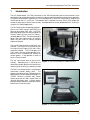
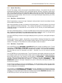
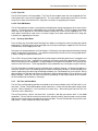
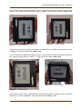
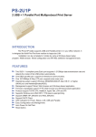
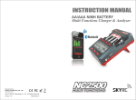
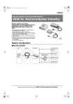
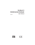
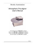
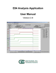
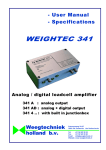
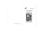
Get Control
Accelerometer Test Tool
User’s Guide
Version 5.0
Get Control Accelerometer Test Tool - Version 5.0
Table of Contents
1
Introduction . . . . . . . . . . . . . . . . . . . . . . . . . . . . . . . . . . . . . . . . . . . . . . . . . . . . . . . . . . . . . . . . . . . 1
2
Operation . . . . . . . . . . . . . . . . . . . . . . . . . . . . . . . . . . . . . . . . . . . . . . . . . . . . . . . . . . . . . . . . . . . .
2.1 Control Panel . . . . . . . . . . . . . . . . . . . . . . . . . . . . . . . . . . . . . . . . . . . . . . . . . . . . . . . . . . . . . .
2.2 Menu Structure . . . . . . . . . . . . . . . . . . . . . . . . . . . . . . . . . . . . . . . . . . . . . . . . . . . . . . . . . . . . .
2.2.1 Numeric Data Entry . . . . . . . . . . . . . . . . . . . . . . . . . . . . . . . . . . . . . . . . . . . . . . . . . . .
2.2.2 Main Menu - Startup Screens . . . . . . . . . . . . . . . . . . . . . . . . . . . . . . . . . . . . . . . . . . . .
2.2.3 Main Menu - Acquire Data . . . . . . . . . . . . . . . . . . . . . . . . . . . . . . . . . . . . . . . . . . . . . .
2.2.4 Connect VibPlot Menu . . . . . . . . . . . . . . . . . . . . . . . . . . . . . . . . . . . . . . . . . . . . . . . . .
2.2.5 Calibration Menu . . . . . . . . . . . . . . . . . . . . . . . . . . . . . . . . . . . . . . . . . . . . . . . . . . . . .
2.2.5.1 Display Static Vibration Menu . . . . . . . . . . . . . . . . . . . . . . . . . . . . . . . . . . . . . . . . .
2.2.5.2 Set Accelerometer Coefficients . . . . . . . . . . . . . . . . . . . . . . . . . . . . . . . . . . . . . . .
2.2.5.3 Flash Vib . . . . . . . . . . . . . . . . . . . . . . . . . . . . . . . . . . . . . . . . . . . . . . . . . . . . . . . .
2.2.5.4 Flash SD Module . . . . . . . . . . . . . . . . . . . . . . . . . . . . . . . . . . . . . . . . . . . . . . . . . .
2.2.6 Recharge Cells Menu . . . . . . . . . . . . . . . . . . . . . . . . . . . . . . . . . . . . . . . . . . . . . . . . . .
2.2.7 Set Time and Date Menu . . . . . . . . . . . . . . . . . . . . . . . . . . . . . . . . . . . . . . . . . . . . . . .
2
2
2
3
3
3
4
4
4
4
5
5
5
5
3
Mechanical . . . . . . . . . . . . . . . . . . . . . . . . . . . . . . . . . . . . . . . . . . . . . . . . . . . . . . . . . . . . . . . . . . .
3.1 Mounting Brackets for 300mm FOUP Installation . . . . . . . . . . . . . . . . . . . . . . . . . . . . . . . . . . .
3.2 Mounting Brackets for 150 mm Reticle Pod Installation . . . . . . . . . . . . . . . . . . . . . . . . . . . . . . .
3.3 Control Panel . . . . . . . . . . . . . . . . . . . . . . . . . . . . . . . . . . . . . . . . . . . . . . . . . . . . . . . . . . . . . .
3.4 Charge Unit . . . . . . . . . . . . . . . . . . . . . . . . . . . . . . . . . . . . . . . . . . . . . . . . . . . . . . . . . . . . . . .
3.4.1 Low-Battery Sense . . . . . . . . . . . . . . . . . . . . . . . . . . . . . . . . . . . . . . . . . . . . . . . . . . . .
3.5 RS-232 Cable . . . . . . . . . . . . . . . . . . . . . . . . . . . . . . . . . . . . . . . . . . . . . . . . . . . . . . . . . . . . . .
3.6 Flash Memory . . . . . . . . . . . . . . . . . . . . . . . . . . . . . . . . . . . . . . . . . . . . . . . . . . . . . . . . . . . . . .
6
6
7
8
8
8
8
8
4
Software . . . . . . . . . . . . . . . . . . . . . . . . . . . . . . . . . . . . . . . . . . . . . . . . . . . . . . . . . . . . . . . . . . . . .
4.1 Data Acquisition . . . . . . . . . . . . . . . . . . . . . . . . . . . . . . . . . . . . . . . . . . . . . . . . . . . . . . . . . . . .
4.2 Data Recording . . . . . . . . . . . . . . . . . . . . . . . . . . . . . . . . . . . . . . . . . . . . . . . . . . . . . . . . . . . . .
4.3 Data Reduction . . . . . . . . . . . . . . . . . . . . . . . . . . . . . . . . . . . . . . . . . . . . . . . . . . . . . . . . . . . . .
4.4 Data Retrieval . . . . . . . . . . . . . . . . . . . . . . . . . . . . . . . . . . . . . . . . . . . . . . . . . . . . . . . . . . . . . .
8
8
8
8
9
5
Technical Support . . . . . . . . . . . . . . . . . . . . . . . . . . . . . . . . . . . . . . . . . . . . . . . . . . . . . . . . . . . . . . 9
i
Get Control Accelerometer Test Tool - Version 5.0
List of Figures
Figure 1 - Vib Tool mounted in 300 mm FOUP . . . . . . . . . . . . . . . . . . . . . . . . . . . . . . . . . . . . . . . . . . . 1
Figure 2 - Vib Tool packaged for Reticle Pod . . . . . . . . . . . . . . . . . . . . . . . . . . . . . . . . . . . . . . . . . . . . 1
Figure 3 - Vib Tool Menu Flowchart . . . . . . . . . . . . . . . . . . . . . . . . . . . . . . . . . . . . . . . . . . . . . . . . . . . 2
Figure 4 - 300mm Plate Mounting Holes . . . . . . . . . . . . . . . . . . . . . . . . . . . . . . . . . . . . . . . . . . . . . . . . 6
Figure 5 - Test Tool with 300 mm Mounting Plate . . . . . . . . . . . . . . . . . . . . . . . . . . . . . . . . . . . . . . . . . 7
Figure 6 - X Axis Positive . . . . . . . . . . . . . . . . . . . . . . . . . . . . . . . . . . . . . . . . . . . . . . . . . . . . . . . . . . 10
Figure 7 - X Axis Negative . . . . . . . . . . . . . . . . . . . . . . . . . . . . . . . . . . . . . . . . . . . . . . . . . . . . . . . . . 10
Figure 8 - Y Axis Positive . . . . . . . . . . . . . . . . . . . . . . . . . . . . . . . . . . . . . . . . . . . . . . . . . . . . . . . . . . 11
Figure 9 - Y Axis Negative . . . . . . . . . . . . . . . . . . . . . . . . . . . . . . . . . . . . . . . . . . . . . . . . . . . . . . . . . 11
Figure 10 - Z Axis Positive . . . . . . . . . . . . . . . . . . . . . . . . . . . . . . . . . . . . . . . . . . . . . . . . . . . . . . . . . 11
Figure 11 - Z Axis Negative . . . . . . . . . . . . . . . . . . . . . . . . . . . . . . . . . . . . . . . . . . . . . . . . . . . . . . . . 11
ii
Get Control Accelerometer Test Tool - Version 5.0
1
Introduction
The GCI Accelerometer Test Tool (also known as the Vib Tool) provides precise measurements of the
acceleration that semiconductor wafers and reticles experience during automatic and manual transportation.
Using three accelerometers mounted in a tri-axial configuration, the Vib Tool simultaneously acquires and
records data on the X, Y, and Z axis. Time-domain data is recorded at a rate of 512 Hz (512 samples per
second, for each axes) to internal flash memory. Recorded data files can be uploaded to the PC for analysis
using the GCI VibPlot Application.
The Vib Tool provides two packaging options,
one for use in wafer carriers and FOUPS, the
other for reticle pods (RSP 150). The FOUP
packaging option ships with mounting plates to
securely mount the tool inside an industrystandard 300mm FOUP. The reticle packaging
option ships with mounting bars to securely
mount the tool inside an industry-standard
150mm reticle pod.
The Control Panel provides the Vib Tool's user
interface. It consists of a 16 character by two
line Liquid Crystal Display (LCD) and a 4-key
membrane keypad. The LCD displays the
Tool's menus and the keypad provides user’
control of menu navigation and selection of
various options. It also provides a switch to
turn the Tool on and off.
The Vib Tool records data to internal flash Figure 1 - Vib Tool mounted in 300 mm FOUP
memory. Recording time is limited by the
remaining available space on the internal flash
memory (up to 24 hours per recording session).
The Tool is self-contained with a rechargeable
nickel-metal hydride battery pack.
The
batteries provide continuous Tool operation for
approximately 28 hours between recharges. A
+15VDC Universal (110/220 VAC) Power
Source plugs into the Tool's Control Panel to
recharge the battery pack. A lithium battery
provides battery backup for calibration values
and the built-in real-time clock.
Figure 2 - Vib Tool packaged for Reticle Pod
1
Get Control Accelerometer Test Tool - Version 5.0
2
Operation
The Control Panel provides the Vib Tool's user interface. The operator selects various options from the
Tool's menus to setup and perform acquisition.
2.1
Control Panel
The Test Tool's Control Panel is visible on the top of the unit. It consists of an anodized aluminum panel
that contains a 16 character by two line LCD, a 4-key membrane keypad, a power entry plug and a 9-pin
(DB-9) RS-232 connector.
The LCD provides display of the Tool's menus. The Up, Down, and Enter keys allow the operator to page
through the menus and select from the various options within the menus. The On/Off switch toggles power
to the Tool.
The RS-232 connector provides the communications interface for uploading recorded data files to the PC
via the GCI VibPlot Application. The power entry plug is used to charge the internal nickel-metal hydride
battery pack using a 15 VDC wall transformer.
2.2
Menu Structure
Figure 3 shows a flowchart of the Vib Tool’s message sequence. Typically, the top line of the LCD displays
the current menu title or mode. The bottom line displays the current option or Tool status. Press the Up and
Down arrow keys to scroll through the menu options. Press the Enter key to select the displayed option.
Figure 3 - Vib Tool Menu Flowchart
2
Get Control Accelerometer Test Tool - Version 5.0
2.2.1
Numeric Data Entry
The test Tool accepts numeric entry using the up and down arrow keys. Use numeric entry to set the
Accelerometer coefficients and the test Tool's internal date and time. When the Tool enters a numeric entry
menu, the current setting of the menu's parameter appears with the cursor located under the left most digit.
Use the Up and Down arrow keys to increment or decrement the digit at the cursor. Press the Enter key to
advance the cursor right one digit. When the cursor is on the right-most digit of the parameter, press Enter
to accept the parameter.
2.2.2
Main Menu - Startup Screens
When first powered up, a sign-on message is displayed, showing the tools internal time and date, firmware
version number and serial number.
After a two second delay, the tool runs through an initialization process. During this process, the time and
date is replaced with the word “Initializing”. This indicates that the tool has successfully booted. If the
“Initializing” message is not displayed after several seconds, the Vib Tool may not have booted properly.
Cycle power to retry.
Part of the inititialization process is a check of available space on the internal flash memory for recorded
data. The Maximum Recording Time is displayed at the end of the initialization step. This message can be
used to determine when data files should be removed from internal storage.
Pressing the ENTER key will clear this message and display the main system menu, starting with the Acquire
Data option.
The Main Menu contains six options: Acquire Data, Connect VibPlot, Calibration, Recharge Cells, and Set
Time and Date. Use the arrow keys to scroll through the options and press the Enter key to select an option.
Sections 2.2.3 through 2.2.7 describe the five main menu options and their functions.
2.2.3
Main Menu - Acquire Data
Press the ENTER key at the MAIN MENU / ACQUIRE DATA screen to initiate a recording session. The Vib
Tool displays a INITIALIZING / PLEASE WAIT message while it prepares internal storage to accept the
recorded data. It then displays a maximum recording time message. The system will automatically
terminate acquisition when the displayed time expires. Alternately, the user can terminate recording
manually.
Press the ENTER key to start recording data. The Vib Tool writes some header information into the data
file, including the tool’s S/N, firmware version number and time and date. While the header information is
being written (which takes a few seconds), the tool displays the RECORDING... / WRITING HEADER
message. When the header has been written, the system initiates it’s time-domain data acquisition module
and begins streaming recorded data to the data file. The display changes to RECORDING... / TIME
DOMAIN DATA. While this message is displayed, the system is continuously recording time-domain data
to internal flash memory.
To terminate the recording session, press the ENTER key. The Vib Tool displays several messages while
it halts it’s acquisition module and closes the recorded data file. Do not turn the Vib Tool’s power off until
the file closing process has completed.
The tool displays the CLOSING FILE / PLEASE WAIT message, followed by a file closed message which
includes the filename (FILE VIB0004.DAT / CLOSED). Pressing the ENTER key will clear this message
and display a message indicating the amount of time-domain data recorded (RECORDED / 00:10:32). Press
the ENTER key to clear this message and return to the Main Menu.
3
Get Control Accelerometer Test Tool - Version 5.0
2.2.4
Connect VibPlot Menu
Press ENTER at the MAIN MENU / CONNECT VIBPLOT message to prepare the Vib Tool for uploading
the data file to the PC using the VibPlot Application. The Vib Tool displays the USE VIBPLOT MENU /
ENTER TO ABORT message.
Connect the Vib Tool’s communications port connector (female DB-9) to an available PC COM port using
a straight through, 9-pin, male to female communications cable (provided). Launch the VibPlot Application
and use the Connect to Vib Tool dialog box, to upload recorded data files. See the separate document
VibPlot Users Guide for details on the VibPlot Application.
Before the connection is initiated, press the ENTER key to abort, and return to the Main Menu. Once a
connection with the PC is made, it must be terminated from the PC - it cannot be aborted using the Vib
Tool’s menu keys.
After connecting with the VibPlot Application, the Vib Tool displays CONNECTED / TO VIBPLOT message.
The Vib Tool will automatically return to the Main Menu when it is disconnected from the PC using the
Connect To Vib Tool dialog box Disconnect button.
2.2.5
Calibration Menu
Press the Enter key at the Main Menu Calibration option to advance to the Display Calibration Menu. The
Calibration menu provides verification of the Tool's operation and a method to change each accelerometer's
coefficients.
The factory sets the accelerometer coefficients and it is not necessary to modify them under normal
operating conditions. They do, however, need to be modified when replacing an accelerometer.
2.2.5.1 Display Static Vibration Menu
Press the Enter key at the Display Calibration Menu to display the X-Axis vibration level. The Tool updates
the current X-axis vibration approximately two times per second. The vibration is displayed as specified by
the Analysis Type option; acquired data is not recorded in this mode. Use the arrow keys to scroll through
the three axes. From the X-axis display, press the Down arrow to display the Y-axis vibration and the Up
arrow to display Z-axis vibration.
Press the Enter key to return to the Main Menu.
Tool verification is possible by taking advantage of the accelerometer’s static acceleration response. The
accelerometers will report approximately 1.0 g of acceleration when they are parallel to earth gravity.
Rotating each accelerometer through earth gravity while monitoring the static response will verify correct
Tool operation. If the reading for any axis varies by more than 10% (±0.10 g), please contact GCI technical
support.
2.2.5.2 Set Accelerometer Coefficients
The Set Accelerometer Coefficients option provides a method to change the accelerometer's factory
coefficients. This is only necessary when replacing one of the Tool's accelerometers. Coefficients must
match those reported by the accelerometer manufacturer. A set of coefficients are shipped with each Test
Tool documenting the three accelerometers installed.
Press the Enter key to advance to the X-axis Offset and Sensitivity menu. Press the Down arrow from the
Set Coefficients Calibration Menu to return to the Main Menu. The Tool displays one numeric entry menu
for each accelerometer for a total of three menus. Each menu prompts for the Accelerometer Offset and
Sensitivity. After setting the three axes coefficients, a final menu allows for entry of the voltage and
temperature offsets. Refer to Section 2.2.1 for instructions on numeric data entry.
4
Get Control Accelerometer Test Tool - Version 5.0
2.2.5.3 Flash Vib
The Vib Tool firmware is field ungradable. The Flash Vib menu option allows the user to upgrade the Test
Tool firmware with a new version supplied by GCI. This menu option should not be used unless a firmware
image file has been received from GCI, along with instructions on upgrading the firmware.
2.2.5.4 Flash SD Module
The Vib Tool hardware includes a second processor dedicated to storage management of the internal flash
memory. The firmware for this second processor is also field ungradable. The Flash Logger menu option
allows the user to upgrade the Time Domain Module firmware with a new version supplied by GCI. This
menu option should not be used unless a firmware image file has been received from GCI, along with
instructions on upgrading the firmware.
2.2.6
Recharge Cells Menu
Press the Enter key at the Main Menu Recharge Cells option to recharge the internal nickel-metal hydride
battery pack. The battery pack can be recharged at any time by connecting the supplied 15 VDC Universal
(110/220 VAC) Power Supply to the Tool.
During the fast recharge operation, the Tool displays a ‘Recharging’ message along with the battery Voltage
and the Temperature measurements. The software automatically terminates the fast charging operation if
it detects voltage or temperature extremes.
The+15 VDC Universal Power Supply provides a trickle charge to the battery pack when it is plugged in and
connected to the Vib Tool. Complete fast charging of the battery pack takes approximately five hours.
When the charge cycle has completed, a ‘Charge Complete’ message will be displayed. Press the Enter key
to return to the main menu. The charge operation may be aborted at any time by pressing the Enter key.
The Tool will display a low-battery warning indicator when it requires charging. An Omega (Ω) appears in
the menus when the Tool is not recording data to indicate the low battery condition. When the battery level
reaches a point that further discharge will damage the battery, the Tool automatically shuts itself off. During
data recording, the Tool does not display the low battery warning indicator before it shuts off due to a low
battery condition. When the Tool shuts itself off during recording, all data up to the point of the shutdown
will be available after the battery is recharged.
2.2.7
Set Time and Date Menu
The Set Time and Date option provides the method to set the time and date of the Vib Tool's built-in realtime clock. The Set Time and Date option contains two menus: One to enter the date and the other to enter
the time. Refer to Section 2.2.1 for instructions on numeric entry. After entering the Date and Time, the
Tool returns to the Main Menu.
The test Tool contains a built-in real-time clock. It provides a two-digit year counter which is Year 2000
compatible. The test Tool will maintain the correct time, date of the month, day of the week, month and twodigit year with correct leap year compensation up to year 2099. The test Tool provides the year with a twodigit counter. It does not provide century information.
5
Get Control Accelerometer Test Tool - Version 5.0
3
Mechanical
3.1
Mounting Brackets for 300mm FOUP Installation
When packaged for 300 mm FOUP installation, the Vib Tool requires 300mm plates that allow it to be
mounted inside the FOUP. Standard 300 mm mounting plates can be attached to the Test Tool using the
supplied hardware.
? shows the location of the mounting holes for 300 mm plates. These mounting holes are on each side of
the Vib Tool. To attached the bottom 300mm mounting plate, use the included 7/16" pan head phillips
screws. Tighten the plate firmly against one side of the tool.
To attach the top 300mm mounting plate, use the included 1" hex head screws, washers and springs (as
detailed on page 11 of this manual). When using the Tool with 300mm mounting plates, please note that
the axes have been rotated. The data recorded will still be reported as X, Y, and Z Axis data, but the Y Axis
will be the vertical axis.
Figure 4 - 300mm Plate Mounting Holes
6
Get Control Accelerometer Test Tool - Version 5.0
Figure 5 shows details on attaching the 300 mm Mounting Plates to the Vib Tool. The bottom plate is
fastened directly to the enclosure. The top plate is mounted with springs between the enclosure and plate.
The top screws are left loose, to allow the unit to align with wafer slots in the FOUP. Once the unit is place
into a FOUP, the hex head or hex socket screws are tightened down (using a 3/16" socket or hex wrench)
to firmly grip the slot fingers. Tighten the screws such that the Vib Tool is secure to the FOUP. Over
tightening may damage the FOUP and/or the Vib Tool.
Figure 5 - Test Tool with 300 mm Mounting Plate
3.2
Mounting Brackets for 150 mm Reticle Pod Installation
When packaged for 150 mm reticle pod installation, the Vib Tool is shipped with all required mounting
brackets attached.
7
Get Control Accelerometer Test Tool - Version 5.0
3.3
Control Panel
The Control Panel is located on the top of the main structure. The Control Panel consists of a membrane
keypad, a power entry port, and a 9-pin female connector. The membrane keypad and connector fasten to
the enclosure such that it remains completely enclosed to minimize particulate generation from the Vib Tool's
PC board.
3.4
Charge Unit
A Universal (110/220 VAC) +15 VDC Power Supply is used to recharge the internal nickel-metal hydride
battery pack.
3.4.1
Low-Battery Sense
The Vib Tool continuously monitors the nickle-metal hydride battery voltage and reports a low-battery
warning by displaying an Omega (Ω)symbol on the LCD (when not recording data). If the battery level falls
below an operational level, the Vib Tool shuts itself off. During recording, a warning is not displayed, but the
Tool will automatically shut off. In all cases, data is retained regardless of the level of the internal batteries.
3.5
RS-232 Cable
A standard 9-Pin adapter cable (P/N 9101-22-030) is used to transfer recorded data to a PC.
3.6
Flash Memory
The Vib Tool includes 1 GB of flash memory used for recorded data storage. The Vib Tool manages the
flash memory similar to a standard PC hard drive. Each recording session is given it’s own data file that is
used to store recorded time-domain data. This allows the user to run multiple, separate recording sessions
before uploading the recorded data to the PC for analysis. Each file is uniquely named, and contains header
information detailing the time and date recording was initiated, along with the Test Tool’s S/N and firmware
version information.
4
Software
4.1
Data Acquisition
The Vib Tool simultaneously samples each of the vibration data channels at a uniform rate of 512 samples
per second.
4.2
Data Recording
The Vib Tool continuously streams time-domain data to internal flash memory. The Vib Tool stores the initial
start time and date and begins recording data points at a uniform rate of 512 points per second on each
channel. Data recording continues until the onboard flash memory fills (up to 24 hours per recording session)
or the user presses the Enter key. Note that the time and date of recording is based on the Vib Tool’s
internal real-time clock. Ensure that the time and data are properly set before initiating a recording session.
4.3
Data Reduction
Data reduction of the recorded time-domain data is handled by the VibPlot Application running on a PC. Use
the VibPlot Application to upload the recorded data files to the PC for analysis. Please see the separate
document VibPlot Users Guide for additional details on available data reduction options.
8
Get Control Accelerometer Test Tool - Version 5.0
4.4
Data Retrieval
The Vib Tool supports data uploading to a Host PC via a standard RS-232 communications port. Using the
VibPlot Application, the user connects to the Vib Tool and requests a list of available data files. The user
selects the desired file and uploads the data to the PC’s hard drive. The file can then be opened by the
VibPlot Application for data reduction and graphical analysis. Please see the separate document VibPlot
Users Guide for additional details on the data retrieval process.
5
Technical Support
If you encounter problems using the Vib Tool, Get Control technical support can be reached the following
ways:
By email at [email protected].
By phone at 1-480-539-0478 (9am - 5pm Mountain Standard Time).
Also see our web site at www.getcontrol.com for additional information about Get Control, Inc.
9
Get Control Accelerometer Test Tool - Version 5.0
6
Operation Verification Application Note
This application note shows how to verify operation of the Vib Tool system. Using the Calibration Display
feature and earth gravity, each of the three axis can be verified. Turn on the Tool and advance to the
Calibration Display menu. Press enter and the real-time DC component of the X-axis vibration is displayed.
The orientation of each axis is drawn on the keypad (newer models) or etched into the top of the enclosure
(older models). From the face of the tool, positive X points to the front of the tool, positive Y points to the
right side of the tool, and positive Z is down into the tool. The orientation of the Z-axis is assumed, not
shown, for clarity.
Verify that the tool’s Calibration Coefficients are set to the accelerometer data sheet specifications provided
with your tool (default nominal is 2.500 V offset and 1000 mV/g sensitivity). These coefficients are stored
in battery-backed RAM. For this verification, it is not critical that they exactly match the data sheets, but they
must be reasonable numbers (close to default nominal) for the Calibration Display feature to operate
properly. If the battery-backed RAM corrupts where the Calibration Coefficients are stored, the tool firmware
detects this and resets them to default nominal. Refer to the User’s Guide for instructions to perform this
verification.
Using the Calibration Display menu, we orient each axis of the test tool perpendicular to earth gravity and
verify its ability to sense this 1g constant. This function is only used for the purpose of verifying test tool
operation. It is not used for calibration and the test tool does not record earth gravity during normal
operation. Several factors affect this measurement including:
•
•
•
The test tool circuits contain DC offsets that make this reading accurate to 10%.
Earth gravity is slightly dependant on geographic location.
It is difficult to hold the tool exactly perpendicular to the earth without a leveling mechanism.
Orient the tool so that its front is facing up, the positive X axis is parallel to earth gravity as shown in Figure
6. Verify that the tool reads +1.00g +/-0.10.
Figure 6 - X Axis Positive
Figure 7 - X Axis Negative
Orient the tool so that its front is facing down, the negative X axis is parallel to earth gravity as shown in
Figure 7. Verify that the tool reads -1.00g +/-0.10.
10
Get Control Accelerometer Test Tool - Version 5.0
Press the Down Key to advance to display the Y Axis. Orient the tool so that its right side is facing up, the
positive Y axis is parallel to earth gravity as shown in Figure 8. Verify that the tool reads +1.00g +/-0.10.
Figure 8 - Y Axis Positive
Figure 9 - Y Axis Negative
Orient the tool so that its right side is facing down, the negative Y axis is parallel to earth gravity as shown
in Figure 9. Verify that the tool reads -1.00g +/-0.10.
Press the Down Key to advance to display the Z Axis. Orient the tool so its top is facing up, the positive Z
axis is parallel to earth gravity as shown in ?. Verify that the tool reads +1.00g +/-0.10.
Figure 11 - Z Axis Negative
Figure 10 - Z Axis Positive
Orient the tool so that its top is facing down (lift the tool over your head), the negative Z axis is parallel to
earth gravity as shown in Figure 11. Verify that the tool reads -1.00g +/- 0.10.
11
Get Control Accelerometer Test Tool - Version 5.0
If the tool measures earth gravity to +/-0.1g (+/-10%) using the Calibration Display feature, it is working
properly.
To remove the system DC offsets to get a more accurate verification, use a level to improve the accuracy
of each axis measurement. Record each positive and negative axis reading. Then subtract the negative
axis measurement from the positive axis measurement and divide this result by 2. This number should be
close to 1.00g. This method removes the tool’s DC offsets from the measurements. However, it does not
account for geographical earth gravity variances or inaccuracies in orienting the tool perpendicular to earth
gravity.
12